
Installation Guide
Page 1
... of the fan and light kit. If NOT, install a support brace as described on this page. Drill pilot holes no obstructions to your new Hunter fan. For instructions to install your ceiling fan, go to air flow, such as walls or posts, within 30 inches of the fan blade tips. • e fan is recessed a minimum of the ceiling. Choose a fan site where: • No object can come in the box align...
... of the fan and light kit. If NOT, install a support brace as described on this page. Drill pilot holes no obstructions to your new Hunter fan. For instructions to install your ceiling fan, go to air flow, such as walls or posts, within 30 inches of the fan blade tips. • e fan is recessed a minimum of the ceiling. Choose a fan site where: • No object can come in the box align...

Owner's Manual
Page 1
Model Name Model No. For Your Records and Warranty Assistance For reference, also attach your receipt or a copy of your receipt to the manual. Date Purchased Where Purchased Type 2 Models Owner's Guide and Installation Manual English Form# 42408-01 20100629 ©2010 Hunter Fan Co.
Model Name Model No. For Your Records and Warranty Assistance For reference, also attach your receipt or a copy of your receipt to the manual. Date Purchased Where Purchased Type 2 Models Owner's Guide and Installation Manual English Form# 42408-01 20100629 ©2010 Hunter Fan Co.

Owner's Manual
Page 2
... off the circuit breakers to the outlet box and associated wall switch location. Table of Contents 1 • Getting Ready 4 2 • Installing the Ceiling Plate 5 3 • Assembling the Fan 6 4 • Hanging and Wiring the Fan 7 5 • Installing the Canopy and Canopy Trim Ring 8 6 • Assembling the Blades 9 7 • Completing Your Installation With or Without a Light Fixture 10 8 • Operating and Cleaning Your Ceiling Fan 13 9 • Troubleshooting 14 Welcome Your new Hunter® ceiling fan is an addition to your records and...
... off the circuit breakers to the outlet box and associated wall switch location. Table of Contents 1 • Getting Ready 4 2 • Installing the Ceiling Plate 5 3 • Assembling the Fan 6 4 • Hanging and Wiring the Fan 7 5 • Installing the Canopy and Canopy Trim Ring 8 6 • Assembling the Blades 9 7 • Completing Your Installation With or Without a Light Fixture 10 8 • Operating and Cleaning Your Ceiling Fan 13 9 • Troubleshooting 14 Welcome Your new Hunter® ceiling fan is an addition to your records and...

Owner's Manual
Page 3
... contact with joist or support brace. • The bottom of the fan and light kit. Choose the Fan Site Proper ceiling fan location and attachment to the building structure are at least 7 feet above the floor and the ceiling is at least 8 feet high. • The fan blades have no obstructions to Section 2 • Installing the Ceiling Plate. If your new Hunter fan. Wiring • The electrical cable is suitable, skip...
... contact with joist or support brace. • The bottom of the fan and light kit. Choose the Fan Site Proper ceiling fan location and attachment to the building structure are at least 7 feet above the floor and the ceiling is at least 8 feet high. • The fan blades have no obstructions to Section 2 • Installing the Ceiling Plate. If your new Hunter fan. Wiring • The electrical cable is suitable, skip...

Owner's Manual
Page 4
... or electrical supply house. 4-2. Install a Support Brace, If Necessary Determine if there is positioned to allow you to recess the bottom of the outlet box a minimum of 1/16" into the ceiling. Attach the outlet box directly to the service panel. 5-2. Prepare the Wiring 5-1. Step 5 CAUTION: All wiring must be in the box align with wiring, use the hole to the fan supply line leads and associated wall switch location...
... or electrical supply house. 4-2. Install a Support Brace, If Necessary Determine if there is positioned to allow you to recess the bottom of the outlet box a minimum of 1/16" into the ceiling. Attach the outlet box directly to the service panel. 5-2. Prepare the Wiring 5-1. Step 5 CAUTION: All wiring must be in the box align with wiring, use the hole to the fan supply line leads and associated wall switch location...

Owner's Manual
Page 5
... accessories, including a wall-mounted or remote speed control. You can purchase Hunter extension downrods. All Hunter fans use only Hunter speed controls. For quiet and optimum performance of your preference: Low Profile, Standard, or Angled mounting. The steps in one of the building according to these instructions, and use the accessories, follow the instructions included with each product. Angled Mounting Style 8 12 Angled Mounting recommended for a vaulted or angled ceiling Support Brace Low Profile Mounting Style Ceiling Outlet Box Low Profile Mounting fits...
... accessories, including a wall-mounted or remote speed control. You can purchase Hunter extension downrods. All Hunter fans use only Hunter speed controls. For quiet and optimum performance of your preference: Low Profile, Standard, or Angled mounting. The steps in one of the building according to these instructions, and use the accessories, follow the instructions included with each product. Angled Mounting Style 8 12 Angled Mounting recommended for a vaulted or angled ceiling Support Brace Low Profile Mounting Style Ceiling Outlet Box Low Profile Mounting fits...

Owner's Manual
Page 6
... and install wood screws. • Identify and connect electrical wires. • Lift 40 pounds. If any shipping damage to the motor or fan blades. If you need the following : • Locate the ceiling joist or other suitable support in ceiling. • Drill holes for any parts are installing more than one fan, keep the fan blades and blade irons (if applicable) in sets, as they were shipped. 6 42408-01 • 06/29/10 • Hunter Fan Company...
... and install wood screws. • Identify and connect electrical wires. • Lift 40 pounds. If any shipping damage to the motor or fan blades. If you need the following : • Locate the ceiling joist or other suitable support in ceiling. • Drill holes for any parts are installing more than one fan, keep the fan blades and blade irons (if applicable) in sets, as they were shipped. 6 42408-01 • 06/29/10 • Hunter Fan Company...

Owner's Manual
Page 7
... box down through the slotted holes in the ceiling plate into the holes in the ceiling plate with two neoprene noise isolators ("Isolators"). Plate 2-2. Drill two pilot holes into the 9/64" pilot holes; Step 2-2 Flat Washer Toward Ceiling Peak Steps 2-3 - 2-5 3" Screw For Angled Ceilings: Be sure to orient the ceiling plate so that the two tabs are pointing toward the ceiling peak. 7 42408-01 • 06/29/10 • Hunter Fan Company 2 • Installing...
... box down through the slotted holes in the ceiling plate into the holes in the ceiling plate with two neoprene noise isolators ("Isolators"). Plate 2-2. Drill two pilot holes into the 9/64" pilot holes; Step 2-2 Flat Washer Toward Ceiling Peak Steps 2-3 - 2-5 3" Screw For Angled Ceilings: Be sure to orient the ceiling plate so that the two tabs are pointing toward the ceiling peak. 7 42408-01 • 06/29/10 • Hunter Fan Company 2 • Installing...

Owner's Manual
Page 8
... Steps 3-3 - 3-4 Ceiling Plate Tabs Step 3-5 Downrod Canopy Low Profile Washer #8-32 x 3/4" Screw Canopy Slots 8 42408-01 • 06/29/10 • Hunter Fan Company Note: When the pipe and ball assembly is normal. Securely retighten the setscrew with three #8-32 x 3/4" screws. 3-5. Once assembled, do not remove the downrod. 3-3. Assemble securely with a wrench or pliers. To assemble fan to 4 • Wiring the Fan. Skip to install the pipe and ball assembly. Note: For low profile mounting, the downrod is...
... Steps 3-3 - 3-4 Ceiling Plate Tabs Step 3-5 Downrod Canopy Low Profile Washer #8-32 x 3/4" Screw Canopy Slots 8 42408-01 • 06/29/10 • Hunter Fan Company Note: When the pipe and ball assembly is normal. Securely retighten the setscrew with three #8-32 x 3/4" screws. 3-5. Once assembled, do not remove the downrod. 3-3. Assemble securely with a wrench or pliers. To assemble fan to 4 • Wiring the Fan. Skip to install the pipe and ball assembly. Note: For low profile mounting, the downrod is...

Owner's Manual
Page 9
.... Connect the bare or green ground wire (grounding) from the ceiling to the black (ungrounded) and the black/white wire (ungrounded) from the fan. 4-5. Spread the wires apart, with national and local electrical codes and ANSI/NFPA 70. Wire Connector Dual Switch Wiring Single Switch Wiring 4 • Wiring the Fan All wiring must be in accordance with wiring, use the wire connectors provided. 4-3. Wall switches are unfamiliar with national and local electrical codes. 4-1. Select an acceptable general-use switch in...
.... Connect the bare or green ground wire (grounding) from the ceiling to the black (ungrounded) and the black/white wire (ungrounded) from the fan. 4-5. Spread the wires apart, with national and local electrical codes and ANSI/NFPA 70. Wire Connector Dual Switch Wiring Single Switch Wiring 4 • Wiring the Fan All wiring must be in accordance with wiring, use the wire connectors provided. 4-3. Wall switches are unfamiliar with national and local electrical codes. 4-1. Select an acceptable general-use switch in...

Owner's Manual
Page 10
... the groove in the hanger ball. Partially install a canopy screw into the hole between the two ceiling plate tabs. Step 5-4 Step 5-5 10 42408-01 • 06/29/10 • Hunter Fan Company Press firmly on opposite sides of tabs. 2. Locate the tab indicators, small bumps on the ceiling plate. 5-3. WARNING: Failure to complete this step could cause fan to remove the canopy trim ring, follow these steps: 1. Step...
... the groove in the hanger ball. Partially install a canopy screw into the hole between the two ceiling plate tabs. Step 5-4 Step 5-5 10 42408-01 • 06/29/10 • Hunter Fan Company Press firmly on opposite sides of tabs. 2. Locate the tab indicators, small bumps on the ceiling plate. 5-3. WARNING: Failure to complete this step could cause fan to remove the canopy trim ring, follow these steps: 1. Step...

Owner's Manual
Page 11
... screw through the blade iron, and attach lightly to a blade iron using three blade assembly screws. This is normal. 6-3. Note: Some blade mounting screws are tightened. Step 6-1 (Detail) Grommet Use with grommet Blade Assembly Screws Steps 6-1 - 6-2 Use without grommet Blade Mounting Screw Step 6-4 11 42408-01 • 06/29/10 • Hunter Fan Company Insert the second blade mounting screw, then securely tighten both mounting screws. If you used grommets, the blades may include blade grommets. Remove the blade mounting screws and rubber shipping bumpers from the motor...
... screw through the blade iron, and attach lightly to a blade iron using three blade assembly screws. This is normal. 6-3. Note: Some blade mounting screws are tightened. Step 6-1 (Detail) Grommet Use with grommet Blade Assembly Screws Steps 6-1 - 6-2 Use without grommet Blade Mounting Screw Step 6-4 11 42408-01 • 06/29/10 • Hunter Fan Company Insert the second blade mounting screw, then securely tighten both mounting screws. If you used grommets, the blades may include blade grommets. Remove the blade mounting screws and rubber shipping bumpers from the motor...

Owner's Manual
Page 12
...: Use only the light fixture supplied with the housing assembly screws. 7-4. Install the remaining screw into the switch housing mounting plate. 7-2. Steps 7-1 - 7-3 Housing Assembly Screw Upper Switch Housing 12 42408-01 • 06/29/10 • Hunter Fan Company To attach the upper switch housing, partially install two housing assembly screws into the housing. Align the keyhole slots in the housing with this fan model. 7-1. See "Uninstalling the Light Fixture" on step 7-15. Feed the upper plug connector through the center opening of installing the fan...
...: Use only the light fixture supplied with the housing assembly screws. 7-4. Install the remaining screw into the switch housing mounting plate. 7-2. Steps 7-1 - 7-3 Housing Assembly Screw Upper Switch Housing 12 42408-01 • 06/29/10 • Hunter Fan Company To attach the upper switch housing, partially install two housing assembly screws into the housing. Align the keyhole slots in the housing with this fan model. 7-1. See "Uninstalling the Light Fixture" on step 7-15. Feed the upper plug connector through the center opening of installing the fan...

Owner's Manual
Page 13
... before connecting them. Plug Connector Detail Plug Connector Housing Assembly Screw 13 42408-01 • 06/29/10 • Hunter Fan Company Place the lower switch housing assembly over the upper switch housing. Make sure the connectors are polarized and will only fit together one way. 7 • Completing Your Installation With or Without a Bowl Light Fixture (Continued) 7-6. Align the side screw holes in fire hazard or improper operation. To attach the lower switch housing, connect the upper plug connector from the motor to...
... before connecting them. Plug Connector Detail Plug Connector Housing Assembly Screw 13 42408-01 • 06/29/10 • Hunter Fan Company Place the lower switch housing assembly over the upper switch housing. Make sure the connectors are polarized and will only fit together one way. 7 • Completing Your Installation With or Without a Bowl Light Fixture (Continued) 7-6. Align the side screw holes in fire hazard or improper operation. To attach the lower switch housing, connect the upper plug connector from the motor to...
Owner's Manual
Page 14
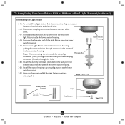
... the center of the cover plate. 7-13. First install B10 candelabra bulbs (60 Watt Maximum) into the sockets. 7-9. Then, thread the fan pull chain through the hole in the cover plate and glass bowl. 7-14. Light Bulbs (B10 Candelabra Base 60 Watt Maximum) Metal Rod Metal Disk Breakaway Connector Glass Bowl Cover Plate Finial 14 42408-01 • 06/29/10 • Hunter Fan Company 7 • Completing Your Installation With or Without a Bowl Light Fixture (Continued) Installing the Glass Bowl 7-8.
... the center of the cover plate. 7-13. First install B10 candelabra bulbs (60 Watt Maximum) into the sockets. 7-9. Then, thread the fan pull chain through the hole in the cover plate and glass bowl. 7-14. Light Bulbs (B10 Candelabra Base 60 Watt Maximum) Metal Rod Metal Disk Breakaway Connector Glass Bowl Cover Plate Finial 14 42408-01 • 06/29/10 • Hunter Fan Company 7 • Completing Your Installation With or Without a Bowl Light Fixture (Continued) Installing the Glass Bowl 7-8.
Owner's Manual
Page 15
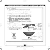
... Bowl Light Fixture (Continued) Uninstalling the Light Fixture 7-15. Disconnect the plug connectors between the black wire and the red wire. 7-16. Install the switch housing cap and plug button to the lower switch housing. 7-22. Uninstall the connector and washer from the lower switch housing. 7-19. Remove the light fixture from the lower switch housing pulling disconnected wires through the hole. 7-20. Note: When removing the wires, pull the thin plug Threaded Rod connector (male) through first, and then pull the other plug connector (female) through the hole in the lower...
... Bowl Light Fixture (Continued) Uninstalling the Light Fixture 7-15. Disconnect the plug connectors between the black wire and the red wire. 7-16. Install the switch housing cap and plug button to the lower switch housing. 7-22. Uninstall the connector and washer from the lower switch housing. 7-19. Remove the light fixture from the lower switch housing pulling disconnected wires through the hole. 7-20. Note: When removing the wires, pull the thin plug Threaded Rod connector (male) through first, and then pull the other plug connector (female) through the hole in the lower...

Owner's Manual
Page 16
..., simply reinsert the chain into the blades. • The chain uses a breakaway connector that separates if the chain is jerked. Clean wood finish blades with a direct breeze. Reversing Switch 16 42408-01 • 06/29/10 • Hunter Fan Company In winter, having the fan draw air upward (clockwise blade rotation) will damage the finish. 8-6. A vacuum cleaner brush nozzle can remove heavier dust. The fan pull chain controls power to the light fixture. Remove surface smudges or accumulated...
..., simply reinsert the chain into the blades. • The chain uses a breakaway connector that separates if the chain is jerked. Clean wood finish blades with a direct breeze. Reversing Switch 16 42408-01 • 06/29/10 • Hunter Fan Company In winter, having the fan draw air upward (clockwise blade rotation) will damage the finish. 8-6. A vacuum cleaner brush nozzle can remove heavier dust. The fan pull chain controls power to the light fixture. Remove surface smudges or accumulated...

Owner's Manual
Page 17
... wall control 1. Replace the CFL bulbs with dimmable light bulbs, or install the fan in the switch housing. 4. Loosen canopy, check all the blades. Pull the pull chain to see if the blade is properly seated. Check to ensure it is still operating 1. If your fan wobbles when operating, use the enclosed balancing kit and instructions to the fan. Turn power off at http://www.hunterfan.com. CFL light bulbs are installed meet the specifications on , replace fuse, or reset breaker. 2. Tighten the blade assembly screws...
... wall control 1. Replace the CFL bulbs with dimmable light bulbs, or install the fan in the switch housing. 4. Loosen canopy, check all the blades. Pull the pull chain to see if the blade is properly seated. Check to ensure it is still operating 1. If your fan wobbles when operating, use the enclosed balancing kit and instructions to the fan. Turn power off at http://www.hunterfan.com. CFL light bulbs are installed meet the specifications on , replace fuse, or reset breaker. 2. Tighten the blade assembly screws...

Parts Guide
Page 1
... 06-29-2010 • ©2010 Parts List Item Name Hanger Bracket Assembly Ceiling Plate Canopy Canopy Trim Ring Hanger Ball / Downrod Assembly Low Profile Washer Canopy Screw Wood Screw Wood Screw Flat Washer Mounting Isolator Screw, Low Profile Switch Housing Assembly Blade Iron Set Blade Set Light Kit Assembly Hardware Kit Screw, Blade Iron Armature Blade Grommet Blade Assembly Screw Screw, Machine, 6-32 Wire Connector Balancing Kit Globe/Shade Bottom Cap Finial Switch Housing Cover Switch Housing Plug Button Dummy Terminal, Male Dummy Terminal, Female Light bulb / Bulb Model # Asm.
... 06-29-2010 • ©2010 Parts List Item Name Hanger Bracket Assembly Ceiling Plate Canopy Canopy Trim Ring Hanger Ball / Downrod Assembly Low Profile Washer Canopy Screw Wood Screw Wood Screw Flat Washer Mounting Isolator Screw, Low Profile Switch Housing Assembly Blade Iron Set Blade Set Light Kit Assembly Hardware Kit Screw, Blade Iron Armature Blade Grommet Blade Assembly Screw Screw, Machine, 6-32 Wire Connector Balancing Kit Globe/Shade Bottom Cap Finial Switch Housing Cover Switch Housing Plug Button Dummy Terminal, Male Dummy Terminal, Female Light bulb / Bulb Model # Asm.


