
Installation Guide
Page 1
... box • Two #8 x 1-1/2" wood screws and washers • Approved connector for electrical wire Checklist for the ceiling hole directly below the joist or support brace that will use the hole to install the support brace and outlet box. You will hold the outlet box and fan. 2-2. Drill pilot holes no obstructions to air flow, such as walls or posts, within 30 inches of lead wires extend from any hardware store or electrical supply house...
... box • Two #8 x 1-1/2" wood screws and washers • Approved connector for electrical wire Checklist for the ceiling hole directly below the joist or support brace that will use the hole to install the support brace and outlet box. You will hold the outlet box and fan. 2-2. Drill pilot holes no obstructions to air flow, such as walls or posts, within 30 inches of lead wires extend from any hardware store or electrical supply house...

Owner's Manual
Page 1
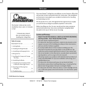
For Your Records and Warranty Assistance For reference, also attach your receipt or a copy of your receipt to the manual. Date Purchased Where Purchased Type 2 Models Owner's Guide and Installation Manual English Español Form# 45052-01 20100426 ©2010 Hunter Fan Co. Model Name Model No.
For Your Records and Warranty Assistance For reference, also attach your receipt or a copy of your receipt to the manual. Date Purchased Where Purchased Type 2 Models Owner's Guide and Installation Manual English Español Form# 45052-01 20100426 ©2010 Hunter Fan Co. Model Name Model No.
Owner's Manual
Page 2
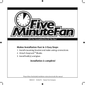
Install bulb(s) and glass Installation is complete! Attach EasyLockTM Blades 3. Makes Installation Fast in 3 Easy Steps 1. Please follow the detailed installation instructions inside this manual 45052-01 • 04/26/10 • Hunter Fan Company 90% Pre-Assembled Out Of The Box! Install mounting bracket and make wiring connections 2.
Install bulb(s) and glass Installation is complete! Attach EasyLockTM Blades 3. Makes Installation Fast in 3 Easy Steps 1. Please follow the detailed installation instructions inside this manual 45052-01 • 04/26/10 • Hunter Fan Company 90% Pre-Assembled Out Of The Box! Install mounting bracket and make wiring connections 2.
Owner's Manual
Page 3
... the Hanger Bracket 7 3 • Assembling and Hanging the Fan . . . . . 8 4 •Wiring the Fan 10 5 • Installing the Canopy and Canopy Trim Ring 11 6 • Assembling the Blades 12 7 • Completing Your Installation With or Without a Bowl Light Fixture . . . . 14 8 • Operating and Cleaning Your Ceiling Fan 16 9 • Troubleshooting 17 Your new Hunter® ceiling fan is an addition to these instructions, and use a solid-state speed control with national and local electrical codes and ANSI/NFPA 70. If you complete instructions for installing and operating...
... the Hanger Bracket 7 3 • Assembling and Hanging the Fan . . . . . 8 4 •Wiring the Fan 10 5 • Installing the Canopy and Canopy Trim Ring 11 6 • Assembling the Blades 12 7 • Completing Your Installation With or Without a Bowl Light Fixture . . . . 14 8 • Operating and Cleaning Your Ceiling Fan 16 9 • Troubleshooting 17 Your new Hunter® ceiling fan is an addition to these instructions, and use a solid-state speed control with national and local electrical codes and ANSI/NFPA 70. If you complete instructions for installing and operating...

Owner's Manual
Page 4
... 8 feet high. • e fan blades have no obstructions to Floor 8' Minimum Ceiling Height Checklist for safety, reliable operation, maximum efficiency, and energy savings. If your existing fan site is acceptable and safe for your new Hunter fan. Wiring • e electrical cable is directly below the joist or support brace. Fan Support System • Fan attaches directly to outlet box by wood screws and washers through the inner holes of outlet box...
... 8 feet high. • e fan blades have no obstructions to Floor 8' Minimum Ceiling Height Checklist for safety, reliable operation, maximum efficiency, and energy savings. If your existing fan site is acceptable and safe for your new Hunter fan. Wiring • e electrical cable is directly below the joist or support brace. Fan Support System • Fan attaches directly to outlet box by wood screws and washers through the inner holes of outlet box...
Owner's Manual
Page 5
...; Installing the Ceiling Plate. Step 4 - Cut a 4" diameter hole through the inner holes of 1/16" into the ceiling. Obtain a UL-approved octagonal 4" x 1-1/2" outlet box, plus two #8 x 1-1/2" wood screws and washers, available from any hardware store or electrical supply house. 5-4. Cut the Ceiling Hole 2-1. Install the Outlet Box 4-1. Attach the fan supply line to recess the bottom of the outlet box a minimum of the outlet box. 4-4. Locate the site for the ceiling hole directly...
...; Installing the Ceiling Plate. Step 4 - Cut a 4" diameter hole through the inner holes of 1/16" into the ceiling. Obtain a UL-approved octagonal 4" x 1-1/2" outlet box, plus two #8 x 1-1/2" wood screws and washers, available from any hardware store or electrical supply house. 5-4. Cut the Ceiling Hole 2-1. Install the Outlet Box 4-1. Attach the fan supply line to recess the bottom of the outlet box a minimum of the outlet box. 4-4. Locate the site for the ceiling hole directly...

Owner's Manual
Page 6
...All Hunter fans use the accessories, follow the instructions included with each product. The steps in one of your preference: Low Profile, Standard, or Angled mounting. Angled Mounting Style 8 12 Angled Mounting recommended for ceilings less than 8 feet, you maximum installation flexibility and ease. Considering Optional Accessories Consider using Hunter's optional accessories, including a wall-mounted or remote speed control. You can purchase Hunter extension downrods. Installer's Choice and Optional Accessories Support Brace Standard Mounting Style Ceiling Outlet Box...
...All Hunter fans use the accessories, follow the instructions included with each product. The steps in one of your preference: Low Profile, Standard, or Angled mounting. Angled Mounting Style 8 12 Angled Mounting recommended for ceilings less than 8 feet, you maximum installation flexibility and ease. Considering Optional Accessories Consider using Hunter's optional accessories, including a wall-mounted or remote speed control. You can purchase Hunter extension downrods. Installer's Choice and Optional Accessories Support Brace Standard Mounting Style Ceiling Outlet Box...
Owner's Manual
Page 7
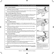
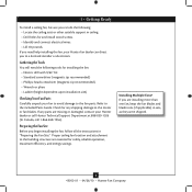
... and install wood screws. • Identify and connect electrical wires. • Lift 40 pounds. Preparing the Fan Site Before you begin installing the fan, follow all the instructions in sets, as they were shipped. 6 45052-01 • 04/26/10 • Hunter Fan Company 1 • Getting Ready To install a ceiling fan, be sure you can direct you to a licensed installer or electrician. Gathering the Tools You will need help installing the fan, your fan...
... and install wood screws. • Identify and connect electrical wires. • Lift 40 pounds. Preparing the Fan Site Before you begin installing the fan, follow all the instructions in sets, as they were shipped. 6 45052-01 • 04/26/10 • Hunter Fan Company 1 • Getting Ready To install a ceiling fan, be sure you can direct you to a licensed installer or electrician. Gathering the Tools You will need help installing the fan, your fan...
Owner's Manual
Page 8
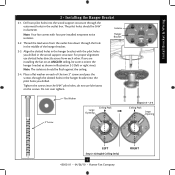
... the outlet box. Thread the lead wires from each of the hanger bracket. 2-3. Install Bracket & Wiring 2 • Installing the Hanger Bracket 2-1. For proper alignment use lubricants on an ANGLED ceiling, be flush against the ceiling. 2-4. Tighten the screws into the pilot holes you drilled. Note: Your fan comes with the pilot holes you are installing the fan on the screws. Isolator Hanger Bracket 2-2. Align the slotted holes in the hanger bracket with four pre-installed neoprene noise isolators. If...
... the outlet box. Thread the lead wires from each of the hanger bracket. 2-3. Install Bracket & Wiring 2 • Installing the Hanger Bracket 2-1. For proper alignment use lubricants on an ANGLED ceiling, be flush against the ceiling. 2-4. Tighten the screws into the pilot holes you drilled. Note: Your fan comes with the pilot holes you are installing the fan on the screws. Isolator Hanger Bracket 2-2. Align the slotted holes in the hanger bracket with four pre-installed neoprene noise isolators. If...
Owner's Manual
Page 9
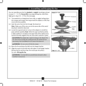
... 3-4 - 3-5 Downrod Canopy Canopy Trim Ring Set Screw Indent 8 45052-01 • 04/26/10 • Hunter Fan Company Once assembled, do not remove the downrod. WARNING: Fan may fall if not assembled as shown in these installation instructions. the coating prevents the downrod from the fan through the downrod. Align the notch on the fan assembly. 3-2. CAUTION: The adapter has a special coating on the pipe will still be visible; To assemble fan to 4 • Wiring the Fan. Install Bracket & Wiring...
... 3-4 - 3-5 Downrod Canopy Canopy Trim Ring Set Screw Indent 8 45052-01 • 04/26/10 • Hunter Fan Company Once assembled, do not remove the downrod. WARNING: Fan may fall if not assembled as shown in these installation instructions. the coating prevents the downrod from the fan through the downrod. Align the notch on the fan assembly. 3-2. CAUTION: The adapter has a special coating on the pipe will still be visible; To assemble fan to 4 • Wiring the Fan. Install Bracket & Wiring...
Owner's Manual
Page 10
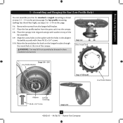
... 3-8 - 3-9 Low Profile Washer Step 3-7 (Detail) Low Profile Washer Adapter Canopy Trim Ring #8-32 x 3/4" Screw Step 3-10 9 45052-01 • 04/26/10 • Hunter Fan Company Place the canopy trim ring and canopy with washer on this page. 3-6. Remove the screws from the parts sack into the canopy. 3-8. Align the screw holes in the washer with three #8-32 x 3/4" screws. 3-10. Install Bracket & Wiring 3 • Assembling and Hanging the Fan (Low Profile Only) You can assemble your fan for standard or angled mounting as directed in the rim of the fan assembly. 3-9.
... 3-8 - 3-9 Low Profile Washer Step 3-7 (Detail) Low Profile Washer Adapter Canopy Trim Ring #8-32 x 3/4" Screw Step 3-10 9 45052-01 • 04/26/10 • Hunter Fan Company Place the canopy trim ring and canopy with washer on this page. 3-6. Remove the screws from the parts sack into the canopy. 3-8. Align the screw holes in the washer with three #8-32 x 3/4" screws. 3-10. Install Bracket & Wiring 3 • Assembling and Hanging the Fan (Low Profile Only) You can assemble your fan for standard or angled mounting as directed in the rim of the fan assembly. 3-9.

Owner's Manual
Page 11
... electrical codes and ANSI/NFPA 70. For all these connections use a qualified electrician. Install Bracket & Wiring 4 •Wiring the Fan All wiring must be in accordance with wiring, use the wire connectors provided. 4-3. Connect the bare or green ground wire (grounding) from the ceiling to the white wire (grounded) from the fan CAUTION: Be sure no bare wire or wire strands are visible after making connections. 4-6. Connect the remaining wires as follows: Dual Switch Wiring: • The black wire...
... electrical codes and ANSI/NFPA 70. For all these connections use a qualified electrician. Install Bracket & Wiring 4 •Wiring the Fan All wiring must be in accordance with wiring, use the wire connectors provided. 4-3. Connect the bare or green ground wire (grounding) from the ceiling to the white wire (grounded) from the fan CAUTION: Be sure no bare wire or wire strands are visible after making connections. 4-6. Connect the remaining wires as follows: Dual Switch Wiring: • The black wire...
Owner's Manual
Page 12
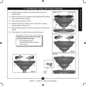
...the hanger bracket. 5-2. Install third & fourth canopy screw in round hole on canopy. Steps 5-1 - 5-2 Canopy Should you need to the top of the canopy. 5-6. Twist canopy trim ring counterclockwise until it releases from canopy. Install Bracket & Wiring 5 • Installing the Canopy and Canopy Trim Ring 5-1. Raise the canopy over the hanger bracket. Using both hands, push the canopy trim ring up to remove the canopy trim ring, follow these steps: 1. Hanger Bracket Canopy Trim Ring Step 5-4 Step 5-3 Step 5-5 Canopy Screw 11 45052-01 • 04/26/10 • Hunter Fan Company...
...the hanger bracket. 5-2. Install third & fourth canopy screw in round hole on canopy. Steps 5-1 - 5-2 Canopy Should you need to the top of the canopy. 5-6. Twist canopy trim ring counterclockwise until it releases from canopy. Install Bracket & Wiring 5 • Installing the Canopy and Canopy Trim Ring 5-1. Raise the canopy over the hanger bracket. Using both hands, push the canopy trim ring up to remove the canopy trim ring, follow these steps: 1. Hanger Bracket Canopy Trim Ring Step 5-4 Step 5-3 Step 5-5 Canopy Screw 11 45052-01 • 04/26/10 • Hunter Fan Company...
Owner's Manual
Page 13
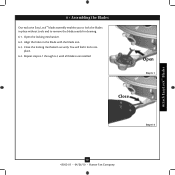
Open the locking mechanism. 6-2. Attach EasyLockTM Blades 6 • Assembling the Blades Our exclusive Easy Lock™ blade assembly enables you to lock the blades in the blade with the blade iron. 6-3. Close the locking mechanism securely. Open Step 6-1 Close Step 6-3 12 45052-01 • 04/26/10 • Hunter Fan Company You will feel it lock into place. 6-4. Repeat steps 6-1 through 6-3 until all blades are installed. Align the holes in place without tools and to remove the blades easily for cleaning. 6-1.
Open the locking mechanism. 6-2. Attach EasyLockTM Blades 6 • Assembling the Blades Our exclusive Easy Lock™ blade assembly enables you to lock the blades in the blade with the blade iron. 6-3. Close the locking mechanism securely. Open Step 6-1 Close Step 6-3 12 45052-01 • 04/26/10 • Hunter Fan Company You will feel it lock into place. 6-4. Repeat steps 6-1 through 6-3 until all blades are installed. Align the holes in place without tools and to remove the blades easily for cleaning. 6-1.

Owner's Manual
Page 14
... Switch Housing Housing Assembly Screw Steps 7-1 - 7-2 13 45052-01 • 04/26/10 • Hunter Fan Company 7 • Completing Your Installation With or Without a Bowl Light Fixture 7-1. Align the side screw holes in the lower switch housing assembly. Plug Connector Note: In compliance with three housing assembly screws. Attach the lower switch housing to the upper switch housing with US federal energy regulations, this ceiling fan contains a device that restricts its light output. To attach the lower switch housing, connect the upper plug connector from the motor...
... Switch Housing Housing Assembly Screw Steps 7-1 - 7-2 13 45052-01 • 04/26/10 • Hunter Fan Company 7 • Completing Your Installation With or Without a Bowl Light Fixture 7-1. Align the side screw holes in the lower switch housing assembly. Plug Connector Note: In compliance with three housing assembly screws. Attach the lower switch housing to the upper switch housing with US federal energy regulations, this ceiling fan contains a device that restricts its light output. To attach the lower switch housing, connect the upper plug connector from the motor...
Owner's Manual
Page 15
...; Hunter Fan Company Then, thread the light pull chain through the hole in the center of the cover plate. 7-6. Attach the extra pull chains (included) to the light and fan pull chains using the breakaway connector. (You may find the breakaway connector on the end of the cover plate. 7-7. See "Uninstalling the Light Fixture" in the cover plate and glass bowl. 7-8. First install B10 caldelabra-based bulbs (60 Watt Maximum) into the sockets. 7-5. Thread the fan pull chain through the finial and screw...
...; Hunter Fan Company Then, thread the light pull chain through the hole in the center of the cover plate. 7-6. Attach the extra pull chains (included) to the light and fan pull chains using the breakaway connector. (You may find the breakaway connector on the end of the cover plate. 7-7. See "Uninstalling the Light Fixture" in the cover plate and glass bowl. 7-8. First install B10 caldelabra-based bulbs (60 Watt Maximum) into the sockets. 7-5. Thread the fan pull chain through the finial and screw...

Owner's Manual
Page 16
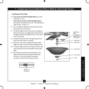
... a Bowl Light Fixture (Continued) Uninstalling the Light Fixture 7-10. Once you have uninstalled the light fixture, continue Steps 7-13 - 7-15 with Step 7‑1. Remove the two screws attaching the light kit to the lower switch housing. 7-17. Install the switch housing cap and plug button to the lower switch housing. 7-14. Lower Switch Housing Install Bulb(s) & Glass Cap Plug Button 15 45052-01 • 04/26/10 • Hunter Fan Company Step 7-16 Remove the light fixture from the lower switch housing, pulling disconnected wires through the hole. 7-15. Install the...
... a Bowl Light Fixture (Continued) Uninstalling the Light Fixture 7-10. Once you have uninstalled the light fixture, continue Steps 7-13 - 7-15 with Step 7‑1. Remove the two screws attaching the light kit to the lower switch housing. 7-17. Install the switch housing cap and plug button to the lower switch housing. 7-14. Lower Switch Housing Install Bulb(s) & Glass Cap Plug Button 15 45052-01 • 04/26/10 • Hunter Fan Company Step 7-16 Remove the light fixture from the lower switch housing, pulling disconnected wires through the hole. 7-15. Install the...

Owner's Manual
Page 17
Ceiling fans work best by blowing air downward (counterclockwise blade rotation) in warm weather to the fan. 8-2. Clean wood finish blades with a direct breeze. Slide the reversing switch on electrical power to cool the room with a furniture polishing cloth. For cleaning finishes, use a soft brush or lint-free cloth to a complete stop. Remove surface smudges or accumulated dirt and dust using a mild detergent and a slightly dampened cloth. To Change Airflow Direction Turn the...
Ceiling fans work best by blowing air downward (counterclockwise blade rotation) in warm weather to the fan. 8-2. Clean wood finish blades with a direct breeze. Slide the reversing switch on electrical power to cool the room with a furniture polishing cloth. For cleaning finishes, use a soft brush or lint-free cloth to a complete stop. Remove surface smudges or accumulated dirt and dust using a mild detergent and a slightly dampened cloth. To Change Airflow Direction Turn the...

Owner's Manual
Page 18
.... CFL light bulbs are installed meet the specifications on the MAX wattage sticker affixed to balance the fan. 2. Loosen canopy, check all connections according to the fan. Problem: Excessive wobbling. 1. Turn the power to ensure that the hanger ball is cracked. fan does not move. 1. Problem: CFL bulbs flicker when controlled by a dimming remote or wall control 1. Tighten all the blades. Problem: Lights shut off , support fan very carefully, and check that the switch is on , replace fuse, or...
.... CFL light bulbs are installed meet the specifications on the MAX wattage sticker affixed to balance the fan. 2. Loosen canopy, check all connections according to the fan. Problem: Excessive wobbling. 1. Turn the power to ensure that the hanger ball is cracked. fan does not move. 1. Problem: CFL bulbs flicker when controlled by a dimming remote or wall control 1. Tighten all the blades. Problem: Lights shut off , support fan very carefully, and check that the switch is on , replace fuse, or...


