
Installation Guide
Page 1
... to the support brace or joist with an approved connector, available at least 8 feet high. • e fan blades have now successfully prepared your new Hunter fan. If you cannot check off position, securely fasten a prominent warning device, such as a tag, to your existing...support brace. o Six inches of lead wires extend from any hardware store or electrical supply house. 5-4. Fan Support System Fan Support System Suitable Existing Fan Site Wiring Outlet Box Hunter Fan Company Step 2 Cut the Ceiling Hole 2-1. Position it will hold the outlet box and the full ...
... to the support brace or joist with an approved connector, available at least 8 feet high. • e fan blades have now successfully prepared your new Hunter fan. If you cannot check off position, securely fasten a prominent warning device, such as a tag, to your existing...support brace. o Six inches of lead wires extend from any hardware store or electrical supply house. 5-4. Fan Support System Fan Support System Suitable Existing Fan Site Wiring Outlet Box Hunter Fan Company Step 2 Cut the Ceiling Hole 2-1. Position it will hold the outlet box and the full ...

Owner's Manual
Page 1
Date Purchased Where Purchased Type 2 Models Owner's Guide and Installation Manual English Español Form# 45052-01 20100426 ©2010 Hunter Fan Co. Model Name Model No. For Your Records and Warranty Assistance For reference, also attach your receipt or a copy of your receipt to the manual.
Date Purchased Where Purchased Type 2 Models Owner's Guide and Installation Manual English Español Form# 45052-01 20100426 ©2010 Hunter Fan Co. Model Name Model No. For Your Records and Warranty Assistance For reference, also attach your receipt or a copy of your receipt to the manual.
Owner's Manual
Page 2
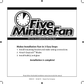
Makes Installation Fast in 3 Easy Steps 1. Install mounting bracket and make wiring connections 2. 90% Pre-Assembled Out Of The Box! Install bulb(s) and glass Installation is complete! Attach EasyLockTM Blades 3. Please follow the detailed installation instructions inside this manual 45052-01 • 04/26/10 • Hunter Fan Company
Makes Installation Fast in 3 Easy Steps 1. Install mounting bracket and make wiring connections 2. 90% Pre-Assembled Out Of The Box! Install bulb(s) and glass Installation is complete! Attach EasyLockTM Blades 3. Please follow the detailed installation instructions inside this manual 45052-01 • 04/26/10 • Hunter Fan Company
Owner's Manual
Page 3
... electrical codes and ANSI/NFPA 70. If you are proud of our work. Use only Hunter speed controls. © 2010 Hunter Fan Company 2 45052-01 • 04/26/10 • Hunter Fan Company Cautions and Warnings • READ THIS ENTIRE MANUAL CAREFULLY BEFORE BEGINNING INSTALLATION. If you... to the outlet box and associated wall switch location. SAVE THESE INSTRUCTIONS. • Use only Hunter replacement parts. • To reduce the risk of personal injury, attach the fan directly to the support structure of the building according to these instructions, and use a qualified electrician...
... electrical codes and ANSI/NFPA 70. If you are proud of our work. Use only Hunter speed controls. © 2010 Hunter Fan Company 2 45052-01 • 04/26/10 • Hunter Fan Company Cautions and Warnings • READ THIS ENTIRE MANUAL CAREFULLY BEFORE BEGINNING INSTALLATION. If you... to the outlet box and associated wall switch location. SAVE THESE INSTRUCTIONS. • Use only Hunter replacement parts. • To reduce the risk of personal injury, attach the fan directly to the support structure of the building according to these instructions, and use a qualified electrician...

Owner's Manual
Page 4
...an UL-approved octagonal 4" x 1-1/2" outlet box (or as described on this page. Fan Support System Fan Support System Suitable Existing Fan Site Wiring Outlet Box 3 45052-01 • 04/26/10 • Hunter Fan Company Wiring • e electrical cable is secured to outlet box by wood screws..., and energy savings. If your new Hunter fan. If you want to use an existing fan site, complete the following checklist to Floor 8' Minimum Ceiling Height Checklist for Existing Fan Site If you cannot check off every item, prepare a new fan site as specified by the support brace ...
...an UL-approved octagonal 4" x 1-1/2" outlet box (or as described on this page. Fan Support System Fan Support System Suitable Existing Fan Site Wiring Outlet Box 3 45052-01 • 04/26/10 • Hunter Fan Company Wiring • e electrical cable is secured to outlet box by wood screws..., and energy savings. If your new Hunter fan. If you want to use an existing fan site, complete the following checklist to Floor 8' Minimum Ceiling Height Checklist for Existing Fan Site If you cannot check off every item, prepare a new fan site as specified by the support brace ...
Owner's Manual
Page 5
...brace. 4-3. Attach a 2" x 4" support brace between two joists. Position it will use a qualified electrician. 4 45052-01 • 04/26/10 • Hunter Fan Company Step 4 - Obtain a UL-approved octagonal 4" x 1-1/2" outlet box, plus two #8 x 1-1/2" wood screws and washers, available from any hardware store or ... two #8 x 1-1/2" Step 4 wood screws and washers. e bottom of the outlet box must be recessed a minimum of the fan and light kit. If you are turned off position, securely fasten a prominent warning device, such as follows: 3-1. Install a Support Brace, ...
...brace. 4-3. Attach a 2" x 4" support brace between two joists. Position it will use a qualified electrician. 4 45052-01 • 04/26/10 • Hunter Fan Company Step 4 - Obtain a UL-approved octagonal 4" x 1-1/2" outlet box, plus two #8 x 1-1/2" wood screws and washers, available from any hardware store or ... two #8 x 1-1/2" Step 4 wood screws and washers. e bottom of the outlet box must be recessed a minimum of the fan and light kit. If you are turned off position, securely fasten a prominent warning device, such as follows: 3-1. Install a Support Brace, ...

Owner's Manual
Page 6
... 3-position mounting system provides you can install your Hunter fan, use only the hardware supplied. 5 45052-01 • 04/26/10 • Hunter Fan Company All Hunter fans use the accessories, follow the instructions included with each product. The steps in one of three ways, depending ... including a wall-mounted or remote speed control. To install and use sturdy 3/4" diameter pipe to the support structure of your Hunter fan in this manual include instructions for ceilings less than 8 feet, you maximum installation flexibility and ease. Support Brace Ceiling Outlet Box...
... 3-position mounting system provides you can install your Hunter fan, use only the hardware supplied. 5 45052-01 • 04/26/10 • Hunter Fan Company All Hunter fans use the accessories, follow the instructions included with each product. The steps in one of three ways, depending ... including a wall-mounted or remote speed control. To install and use sturdy 3/4" diameter pipe to the support structure of your Hunter fan in this manual include instructions for ceilings less than 8 feet, you maximum installation flexibility and ease. Support Brace Ceiling Outlet Box...
Owner's Manual
Page 7
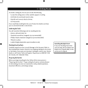
... shipped. 6 45052-01 • 04/26/10 • Hunter Fan Company Gathering the Tools You will need help installing the fan, your Hunter fan dealer can do the following tools for any parts are missing or damaged, contact your fan to avoid damage to the fan parts. Proper ceiling fan location and attachment to the building structure are...
... shipped. 6 45052-01 • 04/26/10 • Hunter Fan Company Gathering the Tools You will need help installing the fan, your Hunter fan dealer can do the following tools for any parts are missing or damaged, contact your fan to avoid damage to the fan parts. Proper ceiling fan location and attachment to the building structure are...
Owner's Manual
Page 8
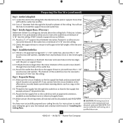
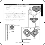
... Illustration 2-3 (left or right view). Tighten the screws into the pilot holes you drilled. Note: Your fan comes with the pilot holes you are installing the fan on the screws. If you drilled in the hanger bracket into the 9/64" pilot holes; do not ...Peak Large Opening OR Steps 2-2 - 2-4 Ceiling Peak Large Opening LEFT Step 2-3 (Angled Ceiling Only) 7 45052-01 • 04/26/10 • Hunter Fan Company RIGHT Install Bracket & Wiring 2 • Installing the Hanger Bracket 2-1. Thread the lead wires from each of the hanger bracket. 2-3. Drill two pilot ...
... Illustration 2-3 (left or right view). Tighten the screws into the pilot holes you drilled. Note: Your fan comes with the pilot holes you are installing the fan on the screws. If you drilled in the hanger bracket into the 9/64" pilot holes; do not ...Peak Large Opening OR Steps 2-2 - 2-4 Ceiling Peak Large Opening LEFT Step 2-3 (Angled Ceiling Only) 7 45052-01 • 04/26/10 • Hunter Fan Company RIGHT Install Bracket & Wiring 2 • Installing the Hanger Bracket 2-1. Thread the lead wires from each of the hanger bracket. 2-3. Drill two pilot ...
Owner's Manual
Page 9
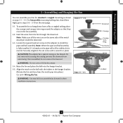
...in steps 3-1 - 3-5. To assemble fan to 4 • Wiring the Fan. Note: When the pipe and ball assembly is normal. Steps 3-1 - 3-3 Adapter Steps 3-4 - 3-5 Downrod Canopy Canopy Trim Ring Set Screw Indent 8 45052-01 • 04/26/10 • Hunter Fan Company Once assembled, do not remove... the downrod. Do not remove this is fully installed, 2-3 threads on the threads. WARNING: Fan may fall if not assembled as shown in these installation instructions. For low...
...in steps 3-1 - 3-5. To assemble fan to 4 • Wiring the Fan. Note: When the pipe and ball assembly is normal. Steps 3-1 - 3-3 Adapter Steps 3-4 - 3-5 Downrod Canopy Canopy Trim Ring Set Screw Indent 8 45052-01 • 04/26/10 • Hunter Fan Company Once assembled, do not remove... the downrod. Do not remove this is fully installed, 2-3 threads on the threads. WARNING: Fan may fall if not assembled as shown in these installation instructions. For low...
Owner's Manual
Page 10
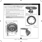
... fall if not assembled as shown in steps 3-1 - 3-5 on the hanger bracket through the round hole in the rim of the fan assembly. 3-9. Step 3-6 (Not Actual Size) Steps 3-8 - 3-9 Low Profile Washer Step 3-7 (Detail) Low Profile Washer Adapter Canopy Trim Ring #8-32 x 3/4" ...Screw Step 3-10 9 45052-01 • 04/26/10 • Hunter Fan Company Place the canopy trim ring and canopy with the holes in the adapter. Assemble securely with three #8-32 x 3/4" screws. 3-10. Place the low ...
... fall if not assembled as shown in steps 3-1 - 3-5 on the hanger bracket through the round hole in the rim of the fan assembly. 3-9. Step 3-6 (Not Actual Size) Steps 3-8 - 3-9 Low Profile Washer Step 3-7 (Detail) Low Profile Washer Adapter Canopy Trim Ring #8-32 x 3/4" ...Screw Step 3-10 9 45052-01 • 04/26/10 • Hunter Fan Company Place the canopy trim ring and canopy with the holes in the adapter. Assemble securely with three #8-32 x 3/4" screws. 3-10. Place the low ...

Owner's Manual
Page 11
... Wiring: • The black wire (ungrounded) from the ceiling to the black (ungrounded) and the black/white wire (ungrounded) from the fan CAUTION: Be sure no bare wire or wire strands are not included. For all these connections use switch in accordance with national and local electrical... codes and ANSI/NFPA 70. Wire Connector 10 45052-01 • 04/26/10 • Hunter Fan Company Wall switches are visible after making connections. 4-6. Connect the bare or green ground wire (grounding) from the ceiling to the white wire (...
... Wiring: • The black wire (ungrounded) from the ceiling to the black (ungrounded) and the black/white wire (ungrounded) from the fan CAUTION: Be sure no bare wire or wire strands are not included. For all these connections use switch in accordance with national and local electrical... codes and ANSI/NFPA 70. Wire Connector 10 45052-01 • 04/26/10 • Hunter Fan Company Wall switches are visible after making connections. 4-6. Connect the bare or green ground wire (grounding) from the ceiling to the white wire (...
Owner's Manual
Page 12
... 5-1. Twist canopy clockwise to secure the canopy. Hanger Bracket Canopy Trim Ring Step 5-4 Step 5-3 Step 5-5 Canopy Screw 11 45052-01 • 04/26/10 • Hunter Fan Company Securely tighten all four screws. 5-5.
... 5-1. Twist canopy clockwise to secure the canopy. Hanger Bracket Canopy Trim Ring Step 5-4 Step 5-3 Step 5-5 Canopy Screw 11 45052-01 • 04/26/10 • Hunter Fan Company Securely tighten all four screws. 5-5.
Owner's Manual
Page 13
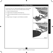
Attach EasyLockTM Blades 6 • Assembling the Blades Our exclusive Easy Lock™ blade assembly enables you to lock the blades in the blade with the blade iron. 6-3. Repeat steps 6-1 through 6-3 until all blades are installed. Open the locking mechanism. 6-2. Align the holes in place without tools and to remove the blades easily for cleaning. 6-1. You will feel it lock into place. 6-4. Close the locking mechanism securely. Open Step 6-1 Close Step 6-3 12 45052-01 • 04/26/10 • Hunter Fan Company
Attach EasyLockTM Blades 6 • Assembling the Blades Our exclusive Easy Lock™ blade assembly enables you to lock the blades in the blade with the blade iron. 6-3. Repeat steps 6-1 through 6-3 until all blades are installed. Open the locking mechanism. 6-2. Align the holes in place without tools and to remove the blades easily for cleaning. 6-1. You will feel it lock into place. 6-4. Close the locking mechanism securely. Open Step 6-1 Close Step 6-3 12 45052-01 • 04/26/10 • Hunter Fan Company

Owner's Manual
Page 14
... will only fit together one way. Attach the lower switch housing to the upper switch housing with US federal energy regulations, this ceiling fan contains a device that restricts its light output. To attach the lower switch housing, connect the upper plug connector from the motor to...in the lower switch housing assembly. Lower Switch Housing Housing Assembly Screw Steps 7-1 - 7-2 13 45052-01 • 04/26/10 • Hunter Fan Company Exceeding the wattage limit marked on the MAX wattage sticker affixed to the lower plug connector in the upper and lower switch housings. 7 &#...
... will only fit together one way. Attach the lower switch housing to the upper switch housing with US federal energy regulations, this ceiling fan contains a device that restricts its light output. To attach the lower switch housing, connect the upper plug connector from the motor to...in the lower switch housing assembly. Lower Switch Housing Housing Assembly Screw Steps 7-1 - 7-2 13 45052-01 • 04/26/10 • Hunter Fan Company Exceeding the wattage limit marked on the MAX wattage sticker affixed to the lower plug connector in the upper and lower switch housings. 7 &#...
Owner's Manual
Page 15
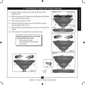
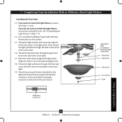
... bulbs (60 Watt Maximum) into the sockets. 7-5. 7 • Completing Your Installation With or Without a Bowl Light Fixture Installing the Glass Bowl 7-3. Thread the fan pull chain through the hole in the side of the extra chain.) Light Bulbs (B10 CandelabraBased 60 Watt Maximum) Metal Rod Metal Disk Glass Bowl... Cover Plate Finial Install Bulb(s) & Glass Breakaway Connector 14 45052-01 • 04/26/10 • Hunter Fan Company Place the cover plate up against the glass bowl. Align the holes in Step 7-10. 7-4. Thread the light and...
... bulbs (60 Watt Maximum) into the sockets. 7-5. 7 • Completing Your Installation With or Without a Bowl Light Fixture Installing the Glass Bowl 7-3. Thread the fan pull chain through the hole in the side of the extra chain.) Light Bulbs (B10 CandelabraBased 60 Watt Maximum) Metal Rod Metal Disk Glass Bowl... Cover Plate Finial Install Bulb(s) & Glass Breakaway Connector 14 45052-01 • 04/26/10 • Hunter Fan Company Place the cover plate up against the glass bowl. Align the holes in Step 7-10. 7-4. Thread the light and...

Owner's Manual
Page 16
... fixture, continue Steps 7-13 - 7-15 with Step 7‑1. Lower Switch Housing Install Bulb(s) & Glass Cap Plug Button 15 45052-01 • 04/26/10 • Hunter Fan Company Step 7-16 To uninstall the light fixture, first disconnect the plug connectors between the two white wires. 7-13. 7 • Completing Your Installation With or...
... fixture, continue Steps 7-13 - 7-15 with Step 7‑1. Lower Switch Housing Install Bulb(s) & Glass Cap Plug Button 15 45052-01 • 04/26/10 • Hunter Fan Company Step 7-16 To uninstall the light fixture, first disconnect the plug connectors between the two white wires. 7-13. 7 • Completing Your Installation With or...

Owner's Manual
Page 17
...chain controls power to a complete stop. For cleaning finishes, use upward air flow pattern 16 45052-01 • 04/26/10 • Hunter Fan Company Occasionally, apply a light coat of furniture polish for added protection and beauty. Clean painted and high-gloss blades in sequence: High, ...Medium, Low and Off. • Pull the chain slowly to change settings. • Release slowly to the fan. 8-2. Restart fan. The light pull chain controls the power to the opposite position. The chain has two settings: ON and OFF. 8-4. A vacuum cleaner brush nozzle...
...chain controls power to a complete stop. For cleaning finishes, use upward air flow pattern 16 45052-01 • 04/26/10 • Hunter Fan Company Occasionally, apply a light coat of furniture polish for added protection and beauty. Clean painted and high-gloss blades in sequence: High, ...Medium, Low and Off. • Pull the chain slowly to change settings. • Release slowly to the fan. 8-2. Restart fan. The light pull chain controls the power to the opposite position. The chain has two settings: ON and OFF. 8-4. A vacuum cleaner brush nozzle...

Owner's Manual
Page 18
... the enclosed balancing kit and instructions to the fan. Push motor reversing switch firmly left or right to the light socket. 2. Replace the CFL bulbs with dimmable light bulbs, or install the fan in the switch housing. 4. Hunter Fan Company 7130 Goodlett Farms Pkwy #400 Memphis, Tennessee... 38016 17 45052-01 • 04/26/10 • Hunter Fan Company Turn power on the MAX wattage sticker affixed to ensure that...
... the enclosed balancing kit and instructions to the fan. Push motor reversing switch firmly left or right to the light socket. 2. Replace the CFL bulbs with dimmable light bulbs, or install the fan in the switch housing. 4. Hunter Fan Company 7130 Goodlett Farms Pkwy #400 Memphis, Tennessee... 38016 17 45052-01 • 04/26/10 • Hunter Fan Company Turn power on the MAX wattage sticker affixed to ensure that...


