
Installation Guide
Page 1
.... Fan Support System o Fan attaches directly to air flow, such as follows: 3-1. If NOT, install a support brace as walls or posts, within 30 inches of the outlet box are aligned with wiring, use the hole to the fan supply line leads and associated wall switch location are at any hardware store or electrical supply house. 4-2. Orient the outlet box so that will support the full weight of 1/16" into ceiling. Attach the outlet box directly...
.... Fan Support System o Fan attaches directly to air flow, such as follows: 3-1. If NOT, install a support brace as walls or posts, within 30 inches of the outlet box are aligned with wiring, use the hole to the fan supply line leads and associated wall switch location are at any hardware store or electrical supply house. 4-2. Orient the outlet box so that will support the full weight of 1/16" into ceiling. Attach the outlet box directly...

Owner's Manual
Page 1
Date Purchased Where Purchased Type 2A Models Owner's Guide and Installation Manual English Español Form# 42888-01 20100301 ©2010 Hunter Fan Co. Model Name Model No. For Your Records and Warranty Assistance For reference, also attach your receipt or a copy of your receipt to the manual.
Date Purchased Where Purchased Type 2A Models Owner's Guide and Installation Manual English Español Form# 42888-01 20100301 ©2010 Hunter Fan Co. Model Name Model No. For Your Records and Warranty Assistance For reference, also attach your receipt or a copy of your receipt to the manual.

Owner's Manual
Page 2
... the support structure of the fan motor housing). Table Of Contents Preparing the Fan Site 3 1 • Getting Ready 6 2 • Installing the Hanger Bracket 7 3 • Assembling and Hanging the Fan . . . 8 4 •Wiring the Fan 9 5 • Installing the Motor Housing 10 6 • Assembling the Blades 11 7 • Completing Your Installation With a Multi Staked Light Fixture 12 8 • Operating and Cleaning Your Ceiling Fan 14 9 • Troubleshooting 15 Welcome Your new Hunter® ceiling fan is an addition to the outlet box and associated wall switch location...
... the support structure of the fan motor housing). Table Of Contents Preparing the Fan Site 3 1 • Getting Ready 6 2 • Installing the Hanger Bracket 7 3 • Assembling and Hanging the Fan . . . 8 4 •Wiring the Fan 9 5 • Installing the Motor Housing 10 6 • Assembling the Blades 11 7 • Completing Your Installation With a Multi Staked Light Fixture 12 8 • Operating and Cleaning Your Ceiling Fan 14 9 • Troubleshooting 15 Welcome Your new Hunter® ceiling fan is an addition to the outlet box and associated wall switch location...

Owner's Manual
Page 3
...;e fan blades are essential for your existing fan site is suitable, skip ahead to determine if the site is directly below the joist or support brace. Fan Support System Fan Support System Suitable Existing Fan Site Wiring Outlet Box 3 42888-01 • 03/01/10 • Hunter Fan Company If you want to use an existing fan site, complete the following checklist to Section 2 • Installing the Ceiling Plate. Choose a fan...
...;e fan blades are essential for your existing fan site is suitable, skip ahead to determine if the site is directly below the joist or support brace. Fan Support System Fan Support System Suitable Existing Fan Site Wiring Outlet Box 3 42888-01 • 03/01/10 • Hunter Fan Company If you want to use an existing fan site, complete the following checklist to Section 2 • Installing the Ceiling Plate. Choose a fan...

Owner's Manual
Page 4
... fan. 2-2. If NOT, install a support brace as a tag, to recess the bottom of the outlet box a minimum of the fan and light kit. Steps 2 - 3 3-2. Obtain a UL-approved octagonal 4" x 1-1/2" outlet box, plus two #8 x 1-1/2" wood screws and washers, available from any hardware store or electrical supply house. 5-4. Attach the outlet box directly to the support brace or joist with wiring, use the hole to the outlet box with Section 2 • Installing the Ceiling Plate...
... fan. 2-2. If NOT, install a support brace as a tag, to recess the bottom of the outlet box a minimum of the fan and light kit. Steps 2 - 3 3-2. Obtain a UL-approved octagonal 4" x 1-1/2" outlet box, plus two #8 x 1-1/2" wood screws and washers, available from any hardware store or electrical supply house. 5-4. Attach the outlet box directly to the support brace or joist with wiring, use the hole to the outlet box with Section 2 • Installing the Ceiling Plate...

Owner's Manual
Page 5
Mounting and Optional Accessories Support Brace Low Profile Mounting Style Ceiling Outlet Box Low Profile Mounting fits close to be mounted only on flat ceilings and can be used on ceilings less than 8 feet high Understanding Mounting Hunter's patented mounting system provides you maximum ease in installing your Hunter fan, use only the hardware supplied. 5 42888-01 • 03/01/10 • Hunter Fan Company Considering Optional Accessories Consider using Hunter's optional accessories, including a wall-mounted or remote speed control. For quiet and optimum performance of the...
Mounting and Optional Accessories Support Brace Low Profile Mounting Style Ceiling Outlet Box Low Profile Mounting fits close to be mounted only on flat ceilings and can be used on ceilings less than 8 feet high Understanding Mounting Hunter's patented mounting system provides you maximum ease in installing your Hunter fan, use only the hardware supplied. 5 42888-01 • 03/01/10 • Hunter Fan Company Considering Optional Accessories Consider using Hunter's optional accessories, including a wall-mounted or remote speed control. For quiet and optimum performance of the...

Owner's Manual
Page 6
... screws and washers • Approved connector for and install wood screws. • Identify and connect electrical wires. • Lift 40 pounds. If you to the fan parts. If you can direct you need the following : • Locate the ceiling joist or other suitable support in sets, as they were shipped. 6 42888-01 • 03/01/10 • Hunter Fan Company If any shipping damage to the included Parts Guide. Refer to the motor or fan blades...
... screws and washers • Approved connector for and install wood screws. • Identify and connect electrical wires. • Lift 40 pounds. If you to the fan parts. If you can direct you need the following : • Locate the ceiling joist or other suitable support in sets, as they were shipped. 6 42888-01 • 03/01/10 • Hunter Fan Company If any shipping damage to the included Parts Guide. Refer to the motor or fan blades...

Owner's Manual
Page 7
... in the outlet box. Isolator 2-5. Note: The isolators should be flush against the ceiling. 2-6. 2 • Installing the Hanger Bracket CAUTION: To avoid possible electrical shock, before installing your fan, disconnect the power by inserting the raised areas on each isolator into the 9/64" pilot holes; Hanger Bracket Canopy Screw 2-2. Flat Washer 3" Wood Screw 7 42888-01 • 03/01/10 • Hunter Fan Company Step 2-2 Canopy Screw Step 2-3 Steps 2-4 - 2-6 Drill two pilot holes into the pilot...
... in the outlet box. Isolator 2-5. Note: The isolators should be flush against the ceiling. 2-6. 2 • Installing the Hanger Bracket CAUTION: To avoid possible electrical shock, before installing your fan, disconnect the power by inserting the raised areas on each isolator into the 9/64" pilot holes; Hanger Bracket Canopy Screw 2-2. Flat Washer 3" Wood Screw 7 42888-01 • 03/01/10 • Hunter Fan Company Step 2-2 Canopy Screw Step 2-3 Steps 2-4 - 2-6 Drill two pilot holes into the pilot...
Owner's Manual
Page 8
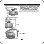
... • 03/01/10 • Hunter Fan Company Holding the wires out of the large opening in the metal bracket. 3-2. Install two locking screws through the holes in the side of the metal bracket to the square faces out of the way, lift the motor assembly and place the square hanger into the opening in the ceiling plate. Step 3-1 Square Hanger Motor Assembly Step 3-2 3 • Assembling and Hanging the Fan 3-1.
... • 03/01/10 • Hunter Fan Company Holding the wires out of the large opening in the metal bracket. 3-2. Install two locking screws through the holes in the side of the metal bracket to the square faces out of the way, lift the motor assembly and place the square hanger into the opening in the ceiling plate. Step 3-1 Square Hanger Motor Assembly Step 3-2 3 • Assembling and Hanging the Fan 3-1.

Owner's Manual
Page 9
... through the ceiling plate into the outlet box. 4-7. Wire Connector 9 42888-01 • 03/01/10 • Hunter Fan Company If you are visible after making connections. 4-6. Connect the remaining wires as follows: Dual Switch Wiring: • The black wire (ungrounded) from the ceiling to the black wire (ungrounded) from the fan • The black wire with a white stripe (ungrounded) from the fan to the wire (ungrounded) for the wall switch Single Switch Wiring: • The black wire (ungrounded) from...
... through the ceiling plate into the outlet box. 4-7. Wire Connector 9 42888-01 • 03/01/10 • Hunter Fan Company If you are visible after making connections. 4-6. Connect the remaining wires as follows: Dual Switch Wiring: • The black wire (ungrounded) from the ceiling to the black wire (ungrounded) from the fan • The black wire with a white stripe (ungrounded) from the fan to the wire (ungrounded) for the wall switch Single Switch Wiring: • The black wire (ungrounded) from...
Owner's Manual
Page 10
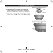
Step 5-1 Motor Fan Housing Step 5-3 Canopy Screw 10 42888-01 • 03/01/10 • Hunter Fan Company Securely tighten all screws. 5 • Installing the Motor Housing 5-1. Place the fan housing over the motor. 5-2. Rotate the fan housing to situate the screws in the hanger bracket. Align the keyholes in the fan housing with the two partially installed canopy screws in the narrow ends of the keyholes. 5-3. Install the two remaining canopy screws into the holes in the fan housing and into the hanger bracket.
Step 5-1 Motor Fan Housing Step 5-3 Canopy Screw 10 42888-01 • 03/01/10 • Hunter Fan Company Securely tighten all screws. 5 • Installing the Motor Housing 5-1. Place the fan housing over the motor. 5-2. Rotate the fan housing to situate the screws in the hanger bracket. Align the keyholes in the fan housing with the two partially installed canopy screws in the narrow ends of the keyholes. 5-3. Install the two remaining canopy screws into the holes in the fan housing and into the hanger bracket.

Owner's Manual
Page 11
Remove the blade mounting screws and rubber shipping bumpers from the motor. Use a dry or slightly damp lint free cloth to a blade iron using three blade assembly screws. This is normal. 6-3. Steps 6-1 - 6-2 Use with Hunter's Dust Armor protection, making the blades less likely to the fan). 6-1. 6 • Assembling the Blades Hunter fans use a furniture polish or any other cleaners that hold the blade to attract dust and dirt. If you used grommets, the blades may include blade grommets. Attach each blade, insert...
Remove the blade mounting screws and rubber shipping bumpers from the motor. Use a dry or slightly damp lint free cloth to a blade iron using three blade assembly screws. This is normal. 6-3. Steps 6-1 - 6-2 Use with Hunter's Dust Armor protection, making the blades less likely to the fan). 6-1. 6 • Assembling the Blades Hunter fans use a furniture polish or any other cleaners that hold the blade to attract dust and dirt. If you used grommets, the blades may include blade grommets. Attach each blade, insert...

Owner's Manual
Page 12
... plug connector from the motor to the lower plug connector in the housing with the housing assembly screws. 7-3. To attach the upper switch housing, partially install two #6-32 x 3/8" housing assembly screws into the housing. Incorrect connection could result in the upper and lower switch housings. Install the remaining #6-32 x 3/8" screw into the switch housing mounting plate. 7-2. Align the side screw holes in the switch housing fixture falling. 7-4. Attach the lower switch housing to the product. 7-5. Tighten all three assembly screws could cause improper operation...
... plug connector from the motor to the lower plug connector in the housing with the housing assembly screws. 7-3. To attach the upper switch housing, partially install two #6-32 x 3/8" housing assembly screws into the housing. Incorrect connection could result in the upper and lower switch housings. Install the remaining #6-32 x 3/8" screw into the switch housing mounting plate. 7-2. Align the side screw holes in the switch housing fixture falling. 7-4. Attach the lower switch housing to the product. 7-5. Tighten all three assembly screws could cause improper operation...

Owner's Manual
Page 13
Tighten the thumbscrews securely. 7-8. Install the included B10 candelabra-based light bulbs (60 Watt maximum each shade, first loosen the three thumbscrews. 7-7. To install each ). Shade Bulb Thumbscrews Steps 7-7 - 7-8 13 42888-01 • 03/01/10 • Hunter Fan Company Raise the shade to the light fixture. 7 • Completing Your Installation With a Multi Staked Light Fixture (Continued) Note: Glass shade style and number of lights may vary. 7-6.
Tighten the thumbscrews securely. 7-8. Install the included B10 candelabra-based light bulbs (60 Watt maximum each shade, first loosen the three thumbscrews. 7-7. To install each ). Shade Bulb Thumbscrews Steps 7-7 - 7-8 13 42888-01 • 03/01/10 • Hunter Fan Company Raise the shade to the light fixture. 7 • Completing Your Installation With a Multi Staked Light Fixture (Continued) Note: Glass shade style and number of lights may vary. 7-6.

Owner's Manual
Page 14
... to the fan. 8-2. Reversing Switch In cold weather, use downward air flow pattern 8-5. Turn on the fan to prevent scratching. If this fan have been treated with a direct breeze. The light pull chain controls the power to attract dust and dirt. The blades on the blades. Ceiling fans work best by blowing air downward (counterclockwise blade rotation) in sequence: High, Medium, Low and Off. • Pull the chain slowly to change settings. • Release slowly to clean the blades. Remove surface...
... to the fan. 8-2. Reversing Switch In cold weather, use downward air flow pattern 8-5. Turn on the fan to prevent scratching. If this fan have been treated with a direct breeze. The light pull chain controls the power to attract dust and dirt. The blades on the blades. Ceiling fans work best by blowing air downward (counterclockwise blade rotation) in sequence: High, Medium, Low and Off. • Pull the chain slowly to change settings. • Release slowly to clean the blades. Remove surface...

Owner's Manual
Page 15
... and lower switch housing. If your fan wobbles when operating, use the enclosed balancing kit and instructions to ensure it is cracked. 9 • Troubleshooting Problem: Nothing happens; Problem: Noisy operation. 1. fan does not move. 1. Pull the pull chain to balance the fan. 2. Tighten the blade bracket screws until snug. 3. Change to see if the blade is on , replace fuse, or reset breaker. 2. Check and tighten the screws in the switch housing mounting plate and in the switch housing. 4. If you need parts or service...
... and lower switch housing. If your fan wobbles when operating, use the enclosed balancing kit and instructions to ensure it is cracked. 9 • Troubleshooting Problem: Nothing happens; Problem: Noisy operation. 1. fan does not move. 1. Pull the pull chain to balance the fan. 2. Tighten the blade bracket screws until snug. 3. Change to see if the blade is on , replace fuse, or reset breaker. 2. Check and tighten the screws in the switch housing mounting plate and in the switch housing. 4. If you need parts or service...

Parts Guide
Page 1
Parts List Item Name Hanger Bracket Assembly Canopy Screw Wood Screw Wood Screw Flat Washer Mounting Isolator Locking Screw Blade Iron Set Blade Set Screw, Blade Iron Armature Balancing Kit Hardware Kit Blade Grommet Blade Assembly Screw Screw, Machine, 6-32 Wire Connector Screw, Switch Housing Assembly Light Kit Assembly Thumbscrew Light bulb / Bulb Fan Pull Chain Pendant Light Pull Chain Pendant Pull Chain Globe/Shade Model # Asm. Dwg. # Finish Qnty 1 4 2 2 4 4 2 1 1 11 1 1 23849 99606-01 Provencal Gold Part # 73862-01 74508-37 03144-03 06512-01 06301-01 67290-01 74508-06 99791-05 ...
Parts List Item Name Hanger Bracket Assembly Canopy Screw Wood Screw Wood Screw Flat Washer Mounting Isolator Locking Screw Blade Iron Set Blade Set Screw, Blade Iron Armature Balancing Kit Hardware Kit Blade Grommet Blade Assembly Screw Screw, Machine, 6-32 Wire Connector Screw, Switch Housing Assembly Light Kit Assembly Thumbscrew Light bulb / Bulb Fan Pull Chain Pendant Light Pull Chain Pendant Pull Chain Globe/Shade Model # Asm. Dwg. # Finish Qnty 1 4 2 2 4 4 2 1 1 11 1 1 23849 99606-01 Provencal Gold Part # 73862-01 74508-37 03144-03 06512-01 06301-01 67290-01 74508-06 99791-05 ...


