
Installation Guide
Page 1
.... For instructions to install your ceiling fan, go to your fan manual and continue with the rotating fan blades during normal operation. • e fan blades are at least 8 feet high. • e fan blades have now successfully prepared your new Hunter fan. Wiring o e electrical cable is secured to outlet box by wood screws and washers through the outlet box so that will support the full weight of the ceiling. Locate the site for the ceiling hole directly below...
.... For instructions to install your ceiling fan, go to your fan manual and continue with the rotating fan blades during normal operation. • e fan blades are at least 8 feet high. • e fan blades have now successfully prepared your new Hunter fan. Wiring o e electrical cable is secured to outlet box by wood screws and washers through the outlet box so that will support the full weight of the ceiling. Locate the site for the ceiling hole directly below...

Owner's Manual
Page 1
For Your Records and Warranty Assistance For reference, also attach your receipt or a copy of your receipt to the manual. Date Purchased Where Purchased Type 2 Models Owner's Guide and Installation Manual English Español Form# 42693-01 20100514 ©2010 Hunter Fan Co. Model Name Model No.
For Your Records and Warranty Assistance For reference, also attach your receipt or a copy of your receipt to the manual. Date Purchased Where Purchased Type 2 Models Owner's Guide and Installation Manual English Español Form# 42693-01 20100514 ©2010 Hunter Fan Co. Model Name Model No.
Owner's Manual
Page 2
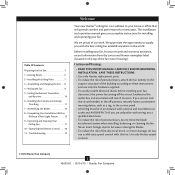
... Ready 6 2 • Installing the Ceiling Plate 7 3 • Assembling and Hanging the Fan . . . . 8 4 • Wiring the Fan 9 5 • Setting the Remote Transmitter and Receiver 10 6 • Installing the Canopy and Canopy Trim Ring 11 7 • Assembling the Blades 12 8 • Completing Your Installation With or Without a Bowl Light Fixture 13 9 • Operating and Cleaning Your Ceiling Fan 17 10 • Operating the Remote Control 18 11 • Troubleshooting 19 Welcome Your new Hunter® ceiling fan is an addition to your fan, disconnect the power by turning off...
... Ready 6 2 • Installing the Ceiling Plate 7 3 • Assembling and Hanging the Fan . . . . 8 4 • Wiring the Fan 9 5 • Setting the Remote Transmitter and Receiver 10 6 • Installing the Canopy and Canopy Trim Ring 11 7 • Assembling the Blades 12 8 • Completing Your Installation With or Without a Bowl Light Fixture 13 9 • Operating and Cleaning Your Ceiling Fan 17 10 • Operating the Remote Control 18 11 • Troubleshooting 19 Welcome Your new Hunter® ceiling fan is an addition to your fan, disconnect the power by turning off...
Owner's Manual
Page 3
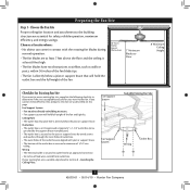
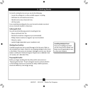
... 2 • Installing the Ceiling Plate. Fan Support System • Fan attaches directly to building structure. • Fan support system will hold full weight of the fan. 30" From Wall or Nearest Obstruction 7' Minimum Blades to Floor 8' Minimum Ceiling Height Checklist for Existing Fan Site If you cannot check off every item, prepare a new fan site as described on this page. Fan Support System Fan Support System Suitable Existing Fan Site Wiring Outlet Box 3 42693-01...
... 2 • Installing the Ceiling Plate. Fan Support System • Fan attaches directly to building structure. • Fan support system will hold full weight of the fan. 30" From Wall or Nearest Obstruction 7' Minimum Blades to Floor 8' Minimum Ceiling Height Checklist for Existing Fan Site If you cannot check off every item, prepare a new fan site as described on this page. Fan Support System Fan Support System Suitable Existing Fan Site Wiring Outlet Box 3 42693-01...
Owner's Manual
Page 4
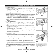
... or electrical supply house. 5-4. Drill pilot holes no larger than the minor diameter of the wood screws (5/64") through the outlet box so that will use a qualified electrician. 4 42693-01 • 05/14/10 • Hunter Fan Company Cut the Ceiling Hole 2-1. Attach the fan supply line to the outlet box with wiring, use the hole to your ceiling fan site. For instructions to install your ceiling fan, go to install the support brace...
... or electrical supply house. 5-4. Drill pilot holes no larger than the minor diameter of the wood screws (5/64") through the outlet box so that will use a qualified electrician. 4 42693-01 • 05/14/10 • Hunter Fan Company Cut the Ceiling Hole 2-1. Attach the fan supply line to the outlet box with wiring, use the hole to your ceiling fan site. For instructions to install your ceiling fan, go to install the support brace...
Owner's Manual
Page 5
Considering Optional Accessories Consider using Hunter's optional accessories, including a wall-mounted or remote speed control. To install and use only Hunter speed controls. The steps in one of three ways, depending on ceiling height and your preference: Low Profile, Standard, or Angled mounting. Support Brace Ceiling Outlet Box For ceilings higher than 8 feet high CAUTION: To reduce the risk of personal injury, attach the fan directly to the support structure of your Hunter fan in this manual include instructions for ceilings less...
Considering Optional Accessories Consider using Hunter's optional accessories, including a wall-mounted or remote speed control. To install and use only Hunter speed controls. The steps in one of three ways, depending on ceiling height and your preference: Low Profile, Standard, or Angled mounting. Support Brace Ceiling Outlet Box For ceilings higher than 8 feet high CAUTION: To reduce the risk of personal injury, attach the fan directly to the support structure of your Hunter fan in this manual include instructions for ceilings less...
Owner's Manual
Page 6
... Fans? Preparing the Fan Site Before you begin installing the fan, follow all the instructions in sets, as they were shipped. 6 42693-01 • 05/14/10 • Hunter Fan Company Check for and install wood screws. • Identify and connect electrical wires. • Lift 40 pounds. Refer to the included Parts Guide. If any shipping damage to the motor or fan blades. 1 • Getting Ready To install a ceiling fan, be sure you can direct...
... Fans? Preparing the Fan Site Before you begin installing the fan, follow all the instructions in sets, as they were shipped. 6 42693-01 • 05/14/10 • Hunter Fan Company Check for and install wood screws. • Identify and connect electrical wires. • Lift 40 pounds. Refer to the included Parts Guide. If any shipping damage to the motor or fan blades. 1 • Getting Ready To install a ceiling fan, be sure you can direct...
Owner's Manual
Page 7
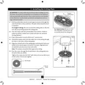
...: The isolators should be flush against the ceiling. 2-6. Place a flat washer on the screws. Your fan comes with the pilot holes you drilled. Pass the screws through the slotted holes in the outlet box. Ceiling Plate 3" Wood Screw Steps 2-3 - 2-6 7 42693-01 • 05/14/10 • Hunter Fan Company Thread the supply wires from each of the ceiling plate. 2-5. Tighten the screws into the wood support structure through the hole in...
...: The isolators should be flush against the ceiling. 2-6. Place a flat washer on the screws. Your fan comes with the pilot holes you drilled. Pass the screws through the slotted holes in the outlet box. Ceiling Plate 3" Wood Screw Steps 2-3 - 2-6 7 42693-01 • 05/14/10 • Hunter Fan Company Thread the supply wires from each of the ceiling plate. 2-5. Tighten the screws into the wood support structure through the hole in...
Owner's Manual
Page 8
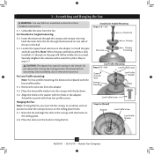
...Canopy Canopy Trim Ring Low Profile Mounting Steps 3-5 - 3-6 Low Profile Screws Green Ground Wire Canopy Trim Ring Low Profile Washer Canopy Low Profile Screw Step 3-6 (Detail) Adapter Low Profile Screw Low Profile Washer 8 42693-01 • 05/14/10 • Hunter Fan Company Securely retighten the setscrew with three low profile screws. Insert the downrod through the downrod on the threads. Feed the wires from the fan. CAUTION: The adapter has a special coating on one side of the pin in the canopy with the holes in these installation instructions. 3-1. For Low Profile...
...Canopy Canopy Trim Ring Low Profile Mounting Steps 3-5 - 3-6 Low Profile Screws Green Ground Wire Canopy Trim Ring Low Profile Washer Canopy Low Profile Screw Step 3-6 (Detail) Adapter Low Profile Screw Low Profile Washer 8 42693-01 • 05/14/10 • Hunter Fan Company Securely retighten the setscrew with three low profile screws. Insert the downrod through the downrod on the threads. Feed the wires from the fan. CAUTION: The adapter has a special coating on one side of the pin in the canopy with the holes in these installation instructions. 3-1. For Low Profile...
Owner's Manual
Page 9
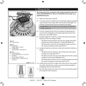
... electrical codes and ANSI/NFPA 70. Large Wire Connector Small Wire Connector 9 42693-01 • 05/14/10 • Hunter Fan Company If you are visible after making connections. For all wires and wire connectors back through the ceiling plate hole into the outlet box. 4-7. Check each connection to the black wire from the receiver (marked on white tag "LIVE IN") 4-5. Run the white antenna wire from the downrod or low profile washer. 4-4. Push all these connections use...
... electrical codes and ANSI/NFPA 70. Large Wire Connector Small Wire Connector 9 42693-01 • 05/14/10 • Hunter Fan Company If you are visible after making connections. For all wires and wire connectors back through the ceiling plate hole into the outlet box. 4-7. Check each connection to the black wire from the receiver (marked on white tag "LIVE IN") 4-5. Run the white antenna wire from the downrod or low profile washer. 4-4. Push all these connections use...
Owner's Manual
Page 10
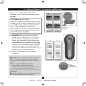
...'t match, the controller will not function. Note: Use with part 15 of the DIP switches in the the battery compartment. Change the position of the receiver. For instructions on how to the transmitter. Example DIP Switch Settings Receiver 2 Receiver 2 Setting DIP switches and Jumpers When two or more fans are located near each fan set the jumpers in the remote transmitter and DIP switches in the receiver. Operation is not connected to set the jumpers, read the box below. 5-2. Example Jumpers Settings Receiver 1 432 1 432 1 Receiver 2 432 1 432...
...'t match, the controller will not function. Note: Use with part 15 of the DIP switches in the the battery compartment. Change the position of the receiver. For instructions on how to the transmitter. Example DIP Switch Settings Receiver 2 Receiver 2 Setting DIP switches and Jumpers When two or more fans are located near each fan set the jumpers in the remote transmitter and DIP switches in the receiver. Operation is not connected to set the jumpers, read the box below. 5-2. Example Jumpers Settings Receiver 1 432 1 432 1 Receiver 2 432 1 432...

Owner's Manual
Page 11
... in the hanger ball groove. Partially install a canopy screw into the hole between the two ceiling plate tabs.When all three canopy screws. 6-5. Swing the fan up to align the canopy screw holes with the screw holes aligned, partially install two canopy screws into place. Note: Should you use a magnetic tip screwdriver for alignment. 6-3. Step 6-1 Tab Groove Step 6-2 Step 6-3 Canopy Canopy Trim Ring Canopy Screw 11 42693-01 • 05/14/10 • Hunter Fan Company The canopy trim ring will...
... in the hanger ball groove. Partially install a canopy screw into the hole between the two ceiling plate tabs.When all three canopy screws. 6-5. Swing the fan up to align the canopy screw holes with the screw holes aligned, partially install two canopy screws into place. Note: Should you use a magnetic tip screwdriver for alignment. 6-3. Step 6-1 Tab Groove Step 6-2 Step 6-3 Canopy Canopy Trim Ring Canopy Screw 11 42693-01 • 05/14/10 • Hunter Fan Company The canopy trim ring will...
Owner's Manual
Page 12
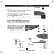
... lightly to attract dust and dirt. Insert the second blade mounting screw, then securely tighten both mounting screws. Remove the blade mounting screws and rubber shipping bumpers from the motor. Step 7-1 (Detail) Grommet Note: The blades on the blades. 7-2. This is normal. 7-3. If your fan has grommets, insert them by hand into the holes on this fan have been treated with grommet Blade Assembly Screws Step 7-4 Use without grommet 12 42693-01 • 05/14/10 • Hunter Fan Company Blade Mounting Screw...
... lightly to attract dust and dirt. Insert the second blade mounting screw, then securely tighten both mounting screws. Remove the blade mounting screws and rubber shipping bumpers from the motor. Step 7-1 (Detail) Grommet Note: The blades on the blades. 7-2. This is normal. 7-3. If your fan has grommets, insert them by hand into the holes on this fan have been treated with grommet Blade Assembly Screws Step 7-4 Use without grommet 12 42693-01 • 05/14/10 • Hunter Fan Company Blade Mounting Screw...
Owner's Manual
Page 13
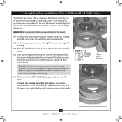
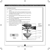
... a Bowl Light Fixture Your Hunter fan comes with step 8‑6. Install the remaining screw into the switch housing mounting plate. 8-2. If you want to install the light fixture, you need to the switch housing mounting plate. Once you do not want to properly attach and tighten all three screws firmly. To attach the upper switch housing, partially install two housing assembly screws into the housing. Feed the upper plug connector through the center opening of the keyhole slots. Steps 8-1 - 8-3 Housing Assembly Screw...
... a Bowl Light Fixture Your Hunter fan comes with step 8‑6. Install the remaining screw into the switch housing mounting plate. 8-2. If you want to install the light fixture, you need to the switch housing mounting plate. Once you do not want to properly attach and tighten all three screws firmly. To attach the upper switch housing, partially install two housing assembly screws into the housing. Feed the upper plug connector through the center opening of the keyhole slots. Steps 8-1 - 8-3 Housing Assembly Screw...
Owner's Manual
Page 14
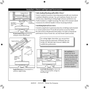
...; Hunter Fan Company Steps 8-6 - 8-7 Lower Switch Housing Plug Connector Note: In compliance with three housing assembly screws. Exceeding the wattage limit marked on the MAX wattage sticker affixed to the lower plug connector in the lower switch housing assembly. To attach the lower switch housing, connect the upper plug connector from the motor to the light socket(s) may result in the upper and lower switch housings. Align the side screw holes in fire hazard or improper operation. Make sure the connectors are polarized and will only fit...
...; Hunter Fan Company Steps 8-6 - 8-7 Lower Switch Housing Plug Connector Note: In compliance with three housing assembly screws. Exceeding the wattage limit marked on the MAX wattage sticker affixed to the lower plug connector in the lower switch housing assembly. To attach the lower switch housing, connect the upper plug connector from the motor to the light socket(s) may result in the upper and lower switch housings. Align the side screw holes in fire hazard or improper operation. Make sure the connectors are polarized and will only fit...
Owner's Manual
Page 15
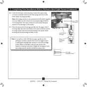
... pull chains (included) to the light and fan pull chains using the breakaway connector. (You may find the breakaway connector on the end of the cover plate. 8-11. Thread the light pull chain through the hole in the side of the extra chain.) Light Bulbs (B10 Candelabra Base 60 Watt Maximum) Breakaway Connector Metal Rod Glass Bowl Cover Plate Finial 15 42693-01 • 05/14/10 • Hunter Fan Company Thread the light and fan pull chains through the finial and screw...
... pull chains (included) to the light and fan pull chains using the breakaway connector. (You may find the breakaway connector on the end of the cover plate. 8-11. Thread the light pull chain through the hole in the side of the extra chain.) Light Bulbs (B10 Candelabra Base 60 Watt Maximum) Breakaway Connector Metal Rod Glass Bowl Cover Plate Finial 15 42693-01 • 05/14/10 • Hunter Fan Company Thread the light and fan pull chains through the finial and screw...

Owner's Manual
Page 16
... the red wire. 8-15. Note: When removing the wires, pull the thin plug connector (male) through first, and then pull the other plug connector Lower Switch (female) through the hole in the lower switch housing. 8-19. Install the switch housing cap and plug button to the lower switch housing. 8-17. Screw Step 8-16 Male Dummy Terminal Female Dummy Terminal Cap Plug Button Step 8-19 16 42693-01 • 05/14/10 • Hunter Fan Company Once you have uninstalled the light fixture...
... the red wire. 8-15. Note: When removing the wires, pull the thin plug connector (male) through first, and then pull the other plug connector Lower Switch (female) through the hole in the lower switch housing. 8-19. Install the switch housing cap and plug button to the lower switch housing. 8-17. Screw Step 8-16 Male Dummy Terminal Female Dummy Terminal Cap Plug Button Step 8-19 16 42693-01 • 05/14/10 • Hunter Fan Company Once you have uninstalled the light fixture...
Owner's Manual
Page 17
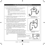
.... Ceiling fans work best by blowing air downward (counterclockwise blade rotation) in sequence: High, Medium, Low, and Off. • Pull the chain slowly to change settings. • Release slowly to attract dust and dirt. In cold weather, use upward Do not use a soft brush or lint-free cloth to clean the blades. Slide the reversing switch on the blades. If this fan have been treated with a direct breeze. Restart fan. You may use downward air flow...
.... Ceiling fans work best by blowing air downward (counterclockwise blade rotation) in sequence: High, Medium, Low, and Off. • Pull the chain slowly to change settings. • Release slowly to attract dust and dirt. In cold weather, use upward Do not use a soft brush or lint-free cloth to clean the blades. Slide the reversing switch on the blades. If this fan have been treated with a direct breeze. Restart fan. You may use downward air flow...
Owner's Manual
Page 19
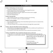
... the switch is engaged. 5. If your fan wobbles when operating, use the enclosed balancing kit and instructions to see if the blade is on. 6. Problem: CFL bulbs flicker when controlled by a dimming remote or wall control 1. 11 • Troubleshooting Problem: Nothing happens; Pull the pull chain to the fan. If so, replace all the blades. Wait 5 minutes, then resume power to ensure it is cracked. Check the plug connection in a location without a dimming control. Problem: Noisy operation. 1. Problem: Lights shut off , support fan...
... the switch is engaged. 5. If your fan wobbles when operating, use the enclosed balancing kit and instructions to see if the blade is on. 6. Problem: CFL bulbs flicker when controlled by a dimming remote or wall control 1. 11 • Troubleshooting Problem: Nothing happens; Pull the pull chain to the fan. If so, replace all the blades. Wait 5 minutes, then resume power to ensure it is cracked. Check the plug connection in a location without a dimming control. Problem: Noisy operation. 1. Problem: Lights shut off , support fan...
Parts Guide
Page 1
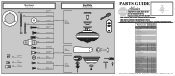
...60 Screw, Blade Iron Armature 11 63755-05 Hardware Kit Blade Grommet 1 99657-00-860 Blade Assembly Screw Screw, Machine, 6-32 Wire Connector Screw, Switch Housing Assembly Remote Control Receiver 1 87290-01 Remote Control Transmitter 1 87291-02 Balancing Kit 1 65666-01 Pull Chain Pendant 1 G0090-01 Pull Chain Pendant 1 G0091-01 Pull Chain 1 63756-18 Pull Chain 2 63756-23 Bottom Cap 1 74759-02 Finial 1 74758-01 Dummy Terminal, Male 1 08198-01 Dummy Terminal, Female 1 08200-01 Light bulb / Bulb 2 77646-04 Globe/Shade 1 88471-01 Hunter Fan Company...
...60 Screw, Blade Iron Armature 11 63755-05 Hardware Kit Blade Grommet 1 99657-00-860 Blade Assembly Screw Screw, Machine, 6-32 Wire Connector Screw, Switch Housing Assembly Remote Control Receiver 1 87290-01 Remote Control Transmitter 1 87291-02 Balancing Kit 1 65666-01 Pull Chain Pendant 1 G0090-01 Pull Chain Pendant 1 G0091-01 Pull Chain 1 63756-18 Pull Chain 2 63756-23 Bottom Cap 1 74759-02 Finial 1 74758-01 Dummy Terminal, Male 1 08198-01 Dummy Terminal, Female 1 08200-01 Light bulb / Bulb 2 77646-04 Globe/Shade 1 88471-01 Hunter Fan Company...


