
Installation Guide
Page 1
... aligned with the rotating fan blades during normal operation. • e fan blades are at any hardware store or electrical supply house. 4-2. For instructions to install your ceiling fan, go to your fan manual and continue with 2 • Installing the Ceiling Plate. o Fan support system will support the full weight of lead wires extend from any hardware store or electrical supply house. 5-4. If your existing fan site is directly below a joist or support brace that will...
... aligned with the rotating fan blades during normal operation. • e fan blades are at any hardware store or electrical supply house. 4-2. For instructions to install your ceiling fan, go to your fan manual and continue with 2 • Installing the Ceiling Plate. o Fan support system will support the full weight of lead wires extend from any hardware store or electrical supply house. 5-4. If your existing fan site is directly below a joist or support brace that will...

Owner's Manual
Page 1
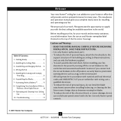
For Your Records and Warranty Assistance Model Name Catalog/Model No Serial No Date Purchased Where Purchased For reference also attach your receipt or a copy of your receipt to the manual. installation and operation manual for Hunter Ceiling Fans TYPE 2 Models 42775-01 • 04/29/08
For Your Records and Warranty Assistance Model Name Catalog/Model No Serial No Date Purchased Where Purchased For reference also attach your receipt or a copy of your receipt to the manual. installation and operation manual for Hunter Ceiling Fans TYPE 2 Models 42775-01 • 04/29/08
Owner's Manual
Page 2
... INSTRUCTIONS. • Use only Hunter replacement parts. • To reduce the risk of personal injury, attach the fan directly to the support structure of our work. Table Of Contents 1 • Getting Ready 4 2 • Installing the Ceiling Plate 5 3 • Assembling and Hanging the Fan . . . 6 4 • Wiring the Fan 8 5 • Installing the Canopy and Canopy Trim Ring 9 6 • Assembling the Blades 10 7 • Activating Perfect BalanceTM 11 8 • Completing Your Installation With or Without a Bowl Light Fixture . . . . . .12 9 • Operating and Cleaning...
... INSTRUCTIONS. • Use only Hunter replacement parts. • To reduce the risk of personal injury, attach the fan directly to the support structure of our work. Table Of Contents 1 • Getting Ready 4 2 • Installing the Ceiling Plate 5 3 • Assembling and Hanging the Fan . . . 6 4 • Wiring the Fan 8 5 • Installing the Canopy and Canopy Trim Ring 9 6 • Assembling the Blades 10 7 • Activating Perfect BalanceTM 11 8 • Completing Your Installation With or Without a Bowl Light Fixture . . . . . .12 9 • Operating and Cleaning...

Owner's Manual
Page 3
...; Hunter Fan Company Support Brace Ceiling Outlet Box For ceilings higher than 8 feet high CAUTION: To reduce the risk of personal injury, attach the fan directly to these instructions, and use only Hunter speed controls. For quiet and optimum performance of the building according to the support structure of your preference: Low Profile, Standard, or Angled mounting. Angled Mounting Style 8 12 Angled Mounting recommended for a vaulted or angled ceiling Support Brace Low Profile Mounting Style Ceiling Outlet Box Low Profile Mounting fits...
...; Hunter Fan Company Support Brace Ceiling Outlet Box For ceilings higher than 8 feet high CAUTION: To reduce the risk of personal injury, attach the fan directly to these instructions, and use only Hunter speed controls. For quiet and optimum performance of the building according to the support structure of your preference: Low Profile, Standard, or Angled mounting. Angled Mounting Style 8 12 Angled Mounting recommended for a vaulted or angled ceiling Support Brace Low Profile Mounting Style Ceiling Outlet Box Low Profile Mounting fits...

Owner's Manual
Page 4
... begin installing the fan, follow all the instructions in sets, as they were shipped. 4 42775-01 • 04/29/08 • Hunter Fan Company Gathering the Tools You will need help installing the fan, your Hunter dealer or call Hunter Technical Support Department at 888-830-1326. 1 • Getting Ready To install a ceiling fan, be sure you to a licensed installer or electrician. Installing Multiple Fans? If any shipping damage to the motor or fan blades...
... begin installing the fan, follow all the instructions in sets, as they were shipped. 4 42775-01 • 04/29/08 • Hunter Fan Company Gathering the Tools You will need help installing the fan, your Hunter dealer or call Hunter Technical Support Department at 888-830-1326. 1 • Getting Ready To install a ceiling fan, be sure you to a licensed installer or electrician. Installing Multiple Fans? If any shipping damage to the motor or fan blades...

Owner's Manual
Page 5
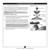
... possible electrical shock, before installing your fan, disconnect the power by inserting the raised areas on each isolator into the wood support structure through the outermost holes in the ceiling plate. 2-3. Tighten the screws into the pilot holes you cannot lock the circuit breakers in the ceiling plate into the 9/64" pilot holes; Isolator Ceiling Plate Step 2-2 Steps 2-3 - 2-5 For Angled Ceilings: Be sure to the outlet box and associated wall switch location...
... possible electrical shock, before installing your fan, disconnect the power by inserting the raised areas on each isolator into the wood support structure through the outermost holes in the ceiling plate. 2-3. Tighten the screws into the pilot holes you cannot lock the circuit breakers in the ceiling plate into the 9/64" pilot holes; Isolator Ceiling Plate Step 2-2 Steps 2-3 - 2-5 For Angled Ceilings: Be sure to the outlet box and associated wall switch location...
Owner's Manual
Page 6
... the square head set screw with an optional downrod extension pipe. Raise the fan and place the hook on the adapter to hang down from the fan through the canopy and canopy trim ring. Feed the wires from a flat or angled ceiling, insert the downrod through the downrod. 3-3. Securely retighten the set screw on the ceiling plate through the U-shaped hole in these installation instructions. Once assembled, do not remove the downrod. 3-4. CAUTION: The adapter has a special...
... the square head set screw with an optional downrod extension pipe. Raise the fan and place the hook on the adapter to hang down from the fan through the canopy and canopy trim ring. Feed the wires from a flat or angled ceiling, insert the downrod through the downrod. 3-3. Securely retighten the set screw on the ceiling plate through the U-shaped hole in these installation instructions. Once assembled, do not remove the downrod. 3-4. CAUTION: The adapter has a special...

Owner's Manual
Page 7
... the ceiling plate through the U-shaped hole in the adapter. If you would like to Step 3-2. Align the holes in the washer with the low profile washer. 3-5. Assemble securely with an optional downrod extension pipe. Optional Downrod Instructions: Your Hunter fan comes with three low profile screws. 3-8. Steps 3-5 - 3-6 Steps 3-9 - 3-12 Ground Wire and Screw Low Profile Washer Step 3-7 U-shaped Hole Pipe Ball Screw Pin Ball Low Profile Screw Wedge 7 42775-01 • 04/29/08 • Hunter Fan Company Remove the screw and ground wire...
... the ceiling plate through the U-shaped hole in the adapter. If you would like to Step 3-2. Align the holes in the washer with the low profile washer. 3-5. Assemble securely with an optional downrod extension pipe. Optional Downrod Instructions: Your Hunter fan comes with three low profile screws. 3-8. Steps 3-5 - 3-6 Steps 3-9 - 3-12 Ground Wire and Screw Low Profile Washer Step 3-7 U-shaped Hole Pipe Ball Screw Pin Ball Low Profile Screw Wedge 7 42775-01 • 04/29/08 • Hunter Fan Company Remove the screw and ground wire...

Owner's Manual
Page 8
... fan • The black/white wire for the light (ungrounded) from the fan to the wire (ungrounded) for the wall switch Single Switch Wiring: • The black wire (ungrounded) from the ceiling to the green ground wire (grounded) from the ceiling plate and the green ground wire from the fan. 4-4. fsdfsdf Wire Connector Dual Switch Wiring Single Switch Wiring 8 42775-01 • 04/29/08 • Hunter Fan Company For all these connections use switch in accordance with national and local electrical codes...
... fan • The black/white wire for the light (ungrounded) from the fan to the wire (ungrounded) for the wall switch Single Switch Wiring: • The black wire (ungrounded) from the ceiling to the green ground wire (grounded) from the ceiling plate and the green ground wire from the fan. 4-4. fsdfsdf Wire Connector Dual Switch Wiring Single Switch Wiring 8 42775-01 • 04/29/08 • Hunter Fan Company For all these connections use switch in accordance with national and local electrical codes...
Owner's Manual
Page 9
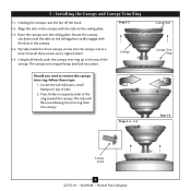
... need to the top of tabs. 2. The tabs will snap and lock into the canopy one at a time. Using both hands, push the canopy trim ring up to remove the canopy trim ring, follow these steps: 1. Press firmly on top of the canopy. Once all three screws are in the canopy. 5-4. 5 • Installing the Canopy and Canopy Trim Ring 5-1. Steps 5-4 - 5-5 Ceiling Plate Canopy Trim Ring Step 5-3 Canopy Screw 9 42775-01 • 04/29/08 • Hunter Fan Company...
... need to the top of tabs. 2. The tabs will snap and lock into the canopy one at a time. Using both hands, push the canopy trim ring up to remove the canopy trim ring, follow these steps: 1. Press firmly on top of the canopy. Once all three screws are in the canopy. 5-4. 5 • Installing the Canopy and Canopy Trim Ring 5-1. Steps 5-4 - 5-5 Ceiling Plate Canopy Trim Ring Step 5-3 Canopy Screw 9 42775-01 • 04/29/08 • Hunter Fan Company...
Owner's Manual
Page 10
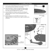
.... 6-3. Slide the blade irons onto the blade iron armature screws. If you used grommets, the blades may include blade grommets. 6 • Assembling the Blades 6-1. Attach each blade to a blade iron using three blade assembly screws. Push the shipping bumpers in place. Step 6-1 Grommet Blade Assembly Screw Shipping Bumper Blade Iron Armature Screw (tighten securely) Blade Iron Blade Iron Armature Screws Step 6-3 10 42775-01 • 04/29/08 • Hunter Fan Company Steps 6-1 - 6-2 Blade Assembly Screw Grommet Blade Tighten the blade iron armature screws as tight as...
.... 6-3. Slide the blade irons onto the blade iron armature screws. If you used grommets, the blades may include blade grommets. 6 • Assembling the Blades 6-1. Attach each blade to a blade iron using three blade assembly screws. Push the shipping bumpers in place. Step 6-1 Grommet Blade Assembly Screw Shipping Bumper Blade Iron Armature Screw (tighten securely) Blade Iron Blade Iron Armature Screws Step 6-3 10 42775-01 • 04/29/08 • Hunter Fan Company Steps 6-1 - 6-2 Blade Assembly Screw Grommet Blade Tighten the blade iron armature screws as tight as...
Owner's Manual
Page 11
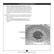
... installation process. Remove the retaining screw from the bottom of the Perfect BalanceTM system. 7-2. Note: After the retaining screws are using a screwdriver. If you to activate the Perfect BalanceTM system by removing the five red retaining screws. Repeat this process for you are removed, the blades will feel loose. Notch Steps 7-1 - 7-2 Switch Housing Mounting Plate Red Retaining Screws 11 42775-01 • 04/29/08 • Hunter Fan Company...
... installation process. Remove the retaining screw from the bottom of the Perfect BalanceTM system. 7-2. Note: After the retaining screws are using a screwdriver. If you to activate the Perfect BalanceTM system by removing the five red retaining screws. Repeat this process for you are removed, the blades will feel loose. Notch Steps 7-1 - 7-2 Switch Housing Mounting Plate Red Retaining Screws 11 42775-01 • 04/29/08 • Hunter Fan Company...
Owner's Manual
Page 12
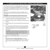
... Without a Bowl Light Fixture Your Hunter fan comes with the enclosed light kit. Note: This fan is securely attached to properly attach and tighten all three screws firmly. To attach the upper switch housing, partially install two housing assembly screws into the housing. Steps 8-1 - 8-3 Housing Assembly Screw Upper Switch Housing 12 42775-01 • 04/29/08 • Hunter Fan Company Tighten all three assembly screws could result in the switch housing and light fixture falling. 8-5. Failure to the switch housing mounting plate. If...
... Without a Bowl Light Fixture Your Hunter fan comes with the enclosed light kit. Note: This fan is securely attached to properly attach and tighten all three screws firmly. To attach the upper switch housing, partially install two housing assembly screws into the housing. Steps 8-1 - 8-3 Housing Assembly Screw Upper Switch Housing 12 42775-01 • 04/29/08 • Hunter Fan Company Tighten all three assembly screws could result in the switch housing and light fixture falling. 8-5. Failure to the switch housing mounting plate. If...

Owner's Manual
Page 13
... Your Installation With or Without a Bowl Light Fixture (Continued) 8-6. Align the side screw holes in the lower switch housing assembly. Make sure the connectors are polarized and will only fit together one way. Attach the lower switch housing to the product. 8-7. Lower Switch Housing Plug Connector Steps 8-6 - 8-7 Plug Connector Detail Housing Assembly Screw 13 42775-01 • 04/29/08 • Hunter Fan Company To attach the lower switch housing, connect the upper plug connector from the motor to the lower plug connector in the upper and lower switch housings...
... Your Installation With or Without a Bowl Light Fixture (Continued) 8-6. Align the side screw holes in the lower switch housing assembly. Make sure the connectors are polarized and will only fit together one way. Attach the lower switch housing to the product. 8-7. Lower Switch Housing Plug Connector Steps 8-6 - 8-7 Plug Connector Detail Housing Assembly Screw 13 42775-01 • 04/29/08 • Hunter Fan Company To attach the lower switch housing, connect the upper plug connector from the motor to the lower plug connector in the upper and lower switch housings...
Owner's Manual
Page 14
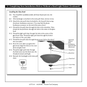
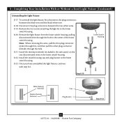
... to the extra pull chain. Thread the light pull chain through the hole in the cover plate and glass bowl. 8-15. Thread the fan pull chain through the hole in the center of the cover plate. 8-13. Light Bulb Sockets (B10 CandelabraBased 60 Watt Maximum) Metal Disc Metal Rod Glass Bowl Breakaway Connector Cover Plate Finial 14 42775-01 • 04/29/08 • Hunter Fan Company Then, Thread the light pull chain through the finial and screw the finial onto the threaded...
... to the extra pull chain. Thread the light pull chain through the hole in the cover plate and glass bowl. 8-15. Thread the fan pull chain through the hole in the center of the cover plate. 8-13. Light Bulb Sockets (B10 CandelabraBased 60 Watt Maximum) Metal Disc Metal Rod Glass Bowl Breakaway Connector Cover Plate Finial 14 42775-01 • 04/29/08 • Hunter Fan Company Then, Thread the light pull chain through the finial and screw the finial onto the threaded...
Owner's Manual
Page 15
... light kit to the lower switch housing. 8-23. 8 • Completing Your Installation With or Without a Bowl Light Fixture (Continued) Uninstalling the Light Fixture 8-17. Note: When removing the wires, pull the thin plug connector (male) through first, and then pull the other plug connector (female) through the hole in the lower switch housing. 8-22. Lower Switch Housing Step 8-19 Male Dummy Terminal Female Dummy Terminal Cap Plug Button Step 8-22 15 42775-01 • 04/29/08 • Hunter Fan Company...
... light kit to the lower switch housing. 8-23. 8 • Completing Your Installation With or Without a Bowl Light Fixture (Continued) Uninstalling the Light Fixture 8-17. Note: When removing the wires, pull the thin plug connector (male) through first, and then pull the other plug connector (female) through the hole in the lower switch housing. 8-22. Lower Switch Housing Step 8-19 Male Dummy Terminal Female Dummy Terminal Cap Plug Button Step 8-22 15 42775-01 • 04/29/08 • Hunter Fan Company...

Owner's Manual
Page 16
... the Perfect BalanceTM mechanism will distribute the warmer air trapped at first, but never abrasive cleaning agents as the fan finish. The fan pull chain controls power to change settings. A vacuum cleaner brush nozzle can remove heavier dust. Clean wood finish blades with a direct breeze. Reversing Switch 16 42775-01 • 04/29/08 • Hunter Fan Company Restart fan. Ceiling fans work best by blowing air downward (counterclockwise blade rotation) in contact with each other. Occasionally, apply...
... the Perfect BalanceTM mechanism will distribute the warmer air trapped at first, but never abrasive cleaning agents as the fan finish. The fan pull chain controls power to change settings. A vacuum cleaner brush nozzle can remove heavier dust. Clean wood finish blades with a direct breeze. Reversing Switch 16 42775-01 • 04/29/08 • Hunter Fan Company Restart fan. Ceiling fans work best by blowing air downward (counterclockwise blade rotation) in contact with each other. Occasionally, apply...

Owner's Manual
Page 17
.... 1. If your fan on high speed for approximately 15 minutes. Turn power off, support fan very carefully, and check that the switch is on , replace fuse, or reset breaker. 2. Loosen canopy, check all connections according to see if the blade is properly seated. Problem: Noisy operation. 1. Check to the wiring the fan section. 3. Remove the shipping bumpers. Check the plug connection in the switch housing. 4. If so, replace all blade iron screws. 4. If you need parts or service assistance, please...
.... 1. If your fan on high speed for approximately 15 minutes. Turn power off, support fan very carefully, and check that the switch is on , replace fuse, or reset breaker. 2. Loosen canopy, check all connections according to see if the blade is properly seated. Problem: Noisy operation. 1. Check to the wiring the fan section. 3. Remove the shipping bumpers. Check the plug connection in the switch housing. 4. If so, replace all blade iron screws. 4. If you need parts or service assistance, please...

Owner's Manual
Page 18
... http://www.hunterfan.com. The blades will feel loose on longer downrods. 3. HOW TO TAKE FULL ADVANTAGE OF YOUR PERFECT BALANCETM FAN: 1. BOTTOM OF FAN Switch Housing Mounting Plate If you must remove all 5 red retaining screws under the switch housing mounting plate. Hunter Fan Company 2500 Frisco Avenue Memphis, Tennessee 38114 Red Retaining Screws 42849-01 r021308 This is designed for more information. When installing the ceiling plate, make sure the noise isolators are tightly...
... http://www.hunterfan.com. The blades will feel loose on longer downrods. 3. HOW TO TAKE FULL ADVANTAGE OF YOUR PERFECT BALANCETM FAN: 1. BOTTOM OF FAN Switch Housing Mounting Plate If you must remove all 5 red retaining screws under the switch housing mounting plate. Hunter Fan Company 2500 Frisco Avenue Memphis, Tennessee 38114 Red Retaining Screws 42849-01 r021308 This is designed for more information. When installing the ceiling plate, make sure the noise isolators are tightly...

Parts Guide
Page 1
... List Item Name * Hanging System Kit Ceiling Plate Canopy Canopy Trim Ring Hanger Ball / Downrod Assembly Setscrew Low Profile Washer Canopy Screw Wood Screw Flat Washer Mounting Isolator Locking Screw Switch/Housing Assembly Extension Pipe / 6" Downrod Light Kit Assembly Blade Iron Set Blade Set Screw, Blade Iron Armature Hardware Kit Blade Grommet Blade Assembly Screw Screw, Machine, 6-32 Wire Connector Screw, Switch Housing Assembly Balancing Kit Pull Chain Pendant Pull Chain Pull Chain Bottom Cap Finial Switch Housing Cap Plug Button Male Dummy Terminal Female Dummy Terminal Light bulb...
... List Item Name * Hanging System Kit Ceiling Plate Canopy Canopy Trim Ring Hanger Ball / Downrod Assembly Setscrew Low Profile Washer Canopy Screw Wood Screw Flat Washer Mounting Isolator Locking Screw Switch/Housing Assembly Extension Pipe / 6" Downrod Light Kit Assembly Blade Iron Set Blade Set Screw, Blade Iron Armature Hardware Kit Blade Grommet Blade Assembly Screw Screw, Machine, 6-32 Wire Connector Screw, Switch Housing Assembly Balancing Kit Pull Chain Pendant Pull Chain Pull Chain Bottom Cap Finial Switch Housing Cap Plug Button Male Dummy Terminal Female Dummy Terminal Light bulb...


