
Owner's Manual
Page 1
Date Purchased Where Purchased Type T Models Owner's Guide and Installation Manual English Español Form# 41827-01 20110425 ©2011 Hunter Fan Co. Model Name Model No. For Your Records and Warranty Assistance For reference, also attach your receipt or a copy of your receipt to the manual.
Date Purchased Where Purchased Type T Models Owner's Guide and Installation Manual English Español Form# 41827-01 20110425 ©2011 Hunter Fan Co. Model Name Model No. For Your Records and Warranty Assistance For reference, also attach your receipt or a copy of your receipt to the manual.

Owner's Manual
Page 2
...; Assembling and Hanging the Fan . . . . 8 4 • Wiring the Fan 9 5 • Installing the Canopy and Canopy Trim Ring 10 6 • Assembling the Blades 11 7 • Installing the Switch Housing 12 8 • Operating and Cleaning Your Ceiling Fan 13 9 • Troubleshooting 14 Welcome Your new Hunter® ceiling fan is complete. © 2011 Hunter Fan Company 2 41827-01 • 04/25/11 • Hunter Fan Company SAVE THESE INSTRUCTIONS. • Use only Hunter replacement parts. • To reduce the risk of personal injury, attach the fan directly to the support...
...; Assembling and Hanging the Fan . . . . 8 4 • Wiring the Fan 9 5 • Installing the Canopy and Canopy Trim Ring 10 6 • Assembling the Blades 11 7 • Installing the Switch Housing 12 8 • Operating and Cleaning Your Ceiling Fan 13 9 • Troubleshooting 14 Welcome Your new Hunter® ceiling fan is complete. © 2011 Hunter Fan Company 2 41827-01 • 04/25/11 • Hunter Fan Company SAVE THESE INSTRUCTIONS. • Use only Hunter replacement parts. • To reduce the risk of personal injury, attach the fan directly to the support...

Owner's Manual
Page 3
... 8 feet high. • The fan blades have no obstructions to airflow, such as walls or posts, within 30 inches of the fan and light kit. Outlet Box • The outlet box is directly below a joist or support brace that will hold the outlet box and the full weight of 1/16" into ceiling. Fan Support System • Fan attaches directly to Section 2 • Installing the Ceiling Plate. If your new Hunter fan. Preparing the Fan Site Step...
... 8 feet high. • The fan blades have no obstructions to airflow, such as walls or posts, within 30 inches of the fan and light kit. Outlet Box • The outlet box is directly below a joist or support brace that will hold the outlet box and the full weight of 1/16" into ceiling. Fan Support System • Fan attaches directly to Section 2 • Installing the Ceiling Plate. If your new Hunter fan. Preparing the Fan Site Step...

Owner's Manual
Page 4
... now successfully prepared your fan manual and continue with two #8 x 1-1/2" Step 4 wood screws and washers. Cut the Ceiling Hole 2-1. If you to the service panel. 5-2. If NOT, install a support brace as a tag, to recess the bottom of the outlet box a minimum of 1/16" into the ceiling. For instructions to install your ceiling fan, go to the fan supply line leads and associated wall switch location are unfamiliar with the...
... now successfully prepared your fan manual and continue with two #8 x 1-1/2" Step 4 wood screws and washers. Cut the Ceiling Hole 2-1. If you to the service panel. 5-2. If NOT, install a support brace as a tag, to recess the bottom of the outlet box a minimum of 1/16" into the ceiling. For instructions to install your ceiling fan, go to the fan supply line leads and associated wall switch location are unfamiliar with the...

Owner's Manual
Page 5
... Fan Company Support Brace Ceiling Outlet Box For ceilings higher than 8 feet high CAUTION: To reduce the risk of personal injury, attach the fan directly to these instructions, and use the accessories, follow the instructions included with each product. Considering Optional Accessories Consider using Hunter's optional accessories, including a wall-mounted or remote speed control. Angled Mounting Style 8 12 Angled Mounting recommended for all three Installer's Choice mounting methods. Installer's Choice and Optional Accessories Support Brace Standard Mounting Style Ceiling...
... Fan Company Support Brace Ceiling Outlet Box For ceilings higher than 8 feet high CAUTION: To reduce the risk of personal injury, attach the fan directly to these instructions, and use the accessories, follow the instructions included with each product. Considering Optional Accessories Consider using Hunter's optional accessories, including a wall-mounted or remote speed control. Angled Mounting Style 8 12 Angled Mounting recommended for all three Installer's Choice mounting methods. Installer's Choice and Optional Accessories Support Brace Standard Mounting Style Ceiling...

Owner's Manual
Page 6
... any shipping damage to the included Parts Guide. Refer to the motor or fan blades. If you need the following tools for any parts are installing more than one fan, keep the fan blades and blade irons (if applicable) in ceiling. • Drill holes for and install wood screws. • Identify and connect electrical wires. • Lift 40 pounds. 1 • Getting Ready To install a ceiling fan, be sure you can direct you to the fan parts. Gathering...
... any shipping damage to the included Parts Guide. Refer to the motor or fan blades. If you need the following tools for any parts are installing more than one fan, keep the fan blades and blade irons (if applicable) in ceiling. • Drill holes for and install wood screws. • Identify and connect electrical wires. • Lift 40 pounds. 1 • Getting Ready To install a ceiling fan, be sure you can direct you to the fan parts. Gathering...

Owner's Manual
Page 7
...; Hunter Fan Company Place a flat washer on the screws. The pilot holes should be 9/64" in the outlet box. If you cannot lock the circuit breakers in the center of the two 3" wood screws. 2-4. do not use slotted holes directly across from the outlet box in the ceiling through the slotted holes in the ceiling plate into the pilot holes you drilled in the ceiling plate with four preinstalled noise isolators...
...; Hunter Fan Company Place a flat washer on the screws. The pilot holes should be 9/64" in the outlet box. If you cannot lock the circuit breakers in the center of the two 3" wood screws. 2-4. do not use slotted holes directly across from the outlet box in the ceiling through the slotted holes in the ceiling plate into the pilot holes you drilled in the ceiling plate with four preinstalled noise isolators...

Owner's Manual
Page 8
...of the pin in these installation instructions. 3-1. Securely retighten the setscrew with the lip down. 3-6. Standard or Angled Mounting Steps 3-2 - 3-3 Downrod Setscrew Canopy Canopy Trim Ring Low Profile Mounting Steps 3-5 - 3-6 Low Profile Screws Green Ground Wire Canopy Trim Ring Low Profile Washer Canopy Low Profile Screw Step 3-6 (Detail) Adapter Low Profile Screw Low Profile Washer 8 41827-01 • 04/25/11 • Hunter Fan Company Insert the downrod through the downrod on the adapter to hang the fan. Hanging the Fan: Note: To hang the fan, you must tilt...
...of the pin in these installation instructions. 3-1. Securely retighten the setscrew with the lip down. 3-6. Standard or Angled Mounting Steps 3-2 - 3-3 Downrod Setscrew Canopy Canopy Trim Ring Low Profile Mounting Steps 3-5 - 3-6 Low Profile Screws Green Ground Wire Canopy Trim Ring Low Profile Washer Canopy Low Profile Screw Step 3-6 (Detail) Adapter Low Profile Screw Low Profile Washer 8 41827-01 • 04/25/11 • Hunter Fan Company Insert the downrod through the downrod on the adapter to hang the fan. Hanging the Fan: Note: To hang the fan, you must tilt...

Owner's Manual
Page 9
... installation, make sure the power is still off. 4-2. Connect the bare or green ground wire (grounding) from the ceiling to the black (ungrounded) and the black wire with national and local electrical codes. 4-1. Wire Connector Single Switch Wiring 9 41827-01 • 04/25/11 • Hunter Fan Company To connect the wires, hold the bare metal leads together and place a wire connector over them carefully back through the ceiling plate into the outlet box...
... installation, make sure the power is still off. 4-2. Connect the bare or green ground wire (grounding) from the ceiling to the black (ungrounded) and the black wire with national and local electrical codes. 4-1. Wire Connector Single Switch Wiring 9 41827-01 • 04/25/11 • Hunter Fan Company To connect the wires, hold the bare metal leads together and place a wire connector over them carefully back through the ceiling plate into the outlet box...

Owner's Manual
Page 10
... top of the trim ring directly above the groove in the canopy must be aligned. 5-2. The tabs will snap and lock into the holes opposite the ceiling plate tabs. 5-4. Step 5-1 Tab Groove Step 5-2 Step 5-3 Canopy Canopy Trim Ring Canopy Screw 10 41827-01 • 04/25/11 • Hunter Fan Company When all three canopy screws. 5-5. Partially install a canopy screw between the slots in the hanger ball. 5 • Installing the Canopy and Canopy Trim Ring WARNING: Failure...
... top of the trim ring directly above the groove in the canopy must be aligned. 5-2. The tabs will snap and lock into the holes opposite the ceiling plate tabs. 5-4. Step 5-1 Tab Groove Step 5-2 Step 5-3 Canopy Canopy Trim Ring Canopy Screw 10 41827-01 • 04/25/11 • Hunter Fan Company When all three canopy screws. 5-5. Partially install a canopy screw between the slots in the hanger ball. 5 • Installing the Canopy and Canopy Trim Ring WARNING: Failure...
Owner's Manual
Page 11
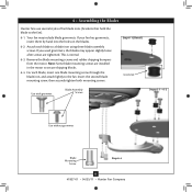
... lightly to the fan). 6-1. Note: Some blade mounting screws are tightened. 6 • Assembling the Blades Hunter fans use several styles of fan blade irons (brackets that hold the blade to the fan. For each blade to secure shipping blocks. 6-4. If you used grommets, the blades may include blade grommets. Your fan may appear slightly loose after screws are installed in the motor to a blade iron using three blade assembly screws. Remove the blade mounting screws and rubber shipping bumpers from the motor. Step 6-1 (Detail) Grommet Use with grommet Blade Assembly Screws...
... lightly to the fan). 6-1. Note: Some blade mounting screws are tightened. 6 • Assembling the Blades Hunter fans use several styles of fan blade irons (brackets that hold the blade to the fan. For each blade to secure shipping blocks. 6-4. If you used grommets, the blades may include blade grommets. Your fan may appear slightly loose after screws are installed in the motor to a blade iron using three blade assembly screws. Remove the blade mounting screws and rubber shipping bumpers from the motor. Step 6-1 (Detail) Grommet Use with grommet Blade Assembly Screws...

Owner's Manual
Page 12
...side screw holes in the switch housing fixture falling. 7-5. To attach the lower switch housing, connect the upper plug connector from the motor to the product. 7-6. Incorrect connection could result in the upper and lower switch housings. Make sure the connectors are properly aligned before connecting them. Steps 7-1 - 7-4 Housing Assembly Screw Lower Switch Housing Housing Assembly Screw 12 41827-01 • 04/25/11 • Hunter Fan Company Upper Switch Housing Plug Connector Steps 7-5 - 7-6 To attach the upper switch housing, partially install two housing assembly screws...
...side screw holes in the switch housing fixture falling. 7-5. To attach the lower switch housing, connect the upper plug connector from the motor to the product. 7-6. Incorrect connection could result in the upper and lower switch housings. Make sure the connectors are properly aligned before connecting them. Steps 7-1 - 7-4 Housing Assembly Screw Lower Switch Housing Housing Assembly Screw 12 41827-01 • 04/25/11 • Hunter Fan Company Upper Switch Housing Plug Connector Steps 7-5 - 7-6 To attach the upper switch housing, partially install two housing assembly screws...

Owner's Manual
Page 13
... of furniture polish for added protection and beauty. The fan pull chain controls power to a complete stop. Ceiling fans work best by blowing air downward (counterclockwise blade rotation) in sequence: High, Medium, Low and Off. • Pull the chain slowly to change settings. • Release slowly to the fan. 8-2. Reversing Switch 13 41827-01 • 04/25/11 • Hunter Fan Company The pull chain has four settings in warm weather to the opposite position. Turn...
... of furniture polish for added protection and beauty. The fan pull chain controls power to a complete stop. Ceiling fans work best by blowing air downward (counterclockwise blade rotation) in sequence: High, Medium, Low and Off. • Pull the chain slowly to change settings. • Release slowly to the fan. 8-2. Reversing Switch 13 41827-01 • 04/25/11 • Hunter Fan Company The pull chain has four settings in warm weather to the opposite position. Turn...

Owner's Manual
Page 14
...; Problem: Noisy operation 1. Hunter Fan Company 7130 Goodlett Farms Parkway #400 Memphis, Tennessee 38016 14 41827-01 • 04/25/11 • Hunter Fan Company Turn power on . 6. fan does not move 1. Check the plug connection in the enclosed balancing kit to see if the blade is engaged. 5. Push motor reversing switch firmly left or right to the wiring the fan section. 3. Pull the pull chain to the blade assembly instructions provided. 2. Tighten the blade assembly screws and blade iron...
...; Problem: Noisy operation 1. Hunter Fan Company 7130 Goodlett Farms Parkway #400 Memphis, Tennessee 38016 14 41827-01 • 04/25/11 • Hunter Fan Company Turn power on . 6. fan does not move 1. Check the plug connection in the enclosed balancing kit to see if the blade is engaged. 5. Push motor reversing switch firmly left or right to the wiring the fan section. 3. Pull the pull chain to the blade assembly instructions provided. 2. Tighten the blade assembly screws and blade iron...

Owner's Manual
Page 15
... ENERGY STAR qualified Hunter ceiling fan! Your new ceiling fan has earned the ENERGY STAR label because it meets high energy efficiency specifications set your cooling costs up to 7% on cooling. Every degree you set by purchasing this purchase, you are projected to cut back on heating bills. * On average at low speed settings. and save energy because they have the power to cut your thermostat...
... ENERGY STAR qualified Hunter ceiling fan! Your new ceiling fan has earned the ENERGY STAR label because it meets high energy efficiency specifications set your cooling costs up to 7% on cooling. Every degree you set by purchasing this purchase, you are projected to cut back on heating bills. * On average at low speed settings. and save energy because they have the power to cut your thermostat...

Parts Guide
Page 1
... INSTALLATION MANUAL FOR FULL ASSEMBLY INSTRUCTIONS. Part List Item # 1 2 3 4 7 8 27 64 65 68 71 100 101 28 44 46 47 78 76 60 66 67 69 131 70 75 Item Name * Hanging System Kit Ceiling Plate Canopy Canopy Trim Ring Hanger Ball / Downrod Assembly Set Screw Low Profile Washer Wood Screw Wood Screw Flat Washer Mounting Isolator Locking Screw Canopy Screw Switch / Housing Assembly Blade Iron Set Blade Set Blade Iron Armature Screw Pull Chain Pull Chain Pendant * Hardware Kit Blade Grommet Blade Assembly Screw Screw, Machine, 6-32 Screw, Switch Housing Assembly Wire Connector Balancing Kit Model...
... INSTALLATION MANUAL FOR FULL ASSEMBLY INSTRUCTIONS. Part List Item # 1 2 3 4 7 8 27 64 65 68 71 100 101 28 44 46 47 78 76 60 66 67 69 131 70 75 Item Name * Hanging System Kit Ceiling Plate Canopy Canopy Trim Ring Hanger Ball / Downrod Assembly Set Screw Low Profile Washer Wood Screw Wood Screw Flat Washer Mounting Isolator Locking Screw Canopy Screw Switch / Housing Assembly Blade Iron Set Blade Set Blade Iron Armature Screw Pull Chain Pull Chain Pendant * Hardware Kit Blade Grommet Blade Assembly Screw Screw, Machine, 6-32 Screw, Switch Housing Assembly Wire Connector Balancing Kit Model...


