
Installation Guide
Page 1
... ceiling. For instructions to install your ceiling fan, go to install the support brace and outlet box. Fan Support System o Fan attaches directly to the support brace or joist with an approved connector, available at least 8 feet high. • e fan blades have now successfully prepared your new Hunter fan. o Fan support system will hold the outlet box and the full weight of the fan. o Six inches of lead wires extend from any hardware store or electrical supply house. 5-4. Locate...
... ceiling. For instructions to install your ceiling fan, go to install the support brace and outlet box. Fan Support System o Fan attaches directly to the support brace or joist with an approved connector, available at least 8 feet high. • e fan blades have now successfully prepared your new Hunter fan. o Fan support system will hold the outlet box and the full weight of the fan. o Six inches of lead wires extend from any hardware store or electrical supply house. 5-4. Locate...
Owner's Manual
Page 28
Hunter Fan Company 2500 Frisco Avenue Memphis, TN 38114
Hunter Fan Company 2500 Frisco Avenue Memphis, TN 38114

Parts Guide
Page 1
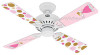
Blade Set Blade Grommet Screw, Blade Assembly Pull Chain Pull Chain Pendant (size and shape may vary) Parts List Model # Asm. Hunter Fan Company 2500 Frisco Avenue Memphis, Tennessee 38114 98000-01-819 10/30/2007 For installation instructions, please refer to the Installation and Operation Manual that came with your Hunter ceiling fan. Dwg. # 23989 97970-01 Finish Flowers Item Name Blade Set Blade Grommet Blade Assembly Screw Pull Chain Pendant Pull Chain Pendant Pull Chain Qnty 1 1 1 2 Part...-25 If you need parts or service assistance, please call 888‑830‑1326 or...
Blade Set Blade Grommet Screw, Blade Assembly Pull Chain Pull Chain Pendant (size and shape may vary) Parts List Model # Asm. Hunter Fan Company 2500 Frisco Avenue Memphis, Tennessee 38114 98000-01-819 10/30/2007 For installation instructions, please refer to the Installation and Operation Manual that came with your Hunter ceiling fan. Dwg. # 23989 97970-01 Finish Flowers Item Name Blade Set Blade Grommet Blade Assembly Screw Pull Chain Pendant Pull Chain Pendant Pull Chain Qnty 1 1 1 2 Part...-25 If you need parts or service assistance, please call 888‑830‑1326 or...

Owner's Manual
Page 1
Model Name Model No. Catalog No. Date Purchased Where Purchased Type 2 Models Owner's Guide and Installation Manual English Español Form# 41343-01 20081223 ©2008 Hunter Fan Co. For Your Records and Warranty Assistance For reference, also attach your receipt or a copy of your receipt to the manual.
Model Name Model No. Catalog No. Date Purchased Where Purchased Type 2 Models Owner's Guide and Installation Manual English Español Form# 41343-01 20081223 ©2008 Hunter Fan Co. For Your Records and Warranty Assistance For reference, also attach your receipt or a copy of your receipt to the manual.

Owner's Manual
Page 2
... the Fan 6 4 • Hanging and Wiring the Fan 7 5 • Installing the Canopy and Canopy Trim Ring 8 6 • Assembling the Blades 9 7 • Completing Your Installation With or Without a Light Fixture 10 8 • Operating the Remote Control _ and Mounting the Holder 12 9 • Operating and Cleaning Your Ceiling Fan 13 10 • Troubleshooting 14 Welcome Your new Hunter® ceiling fan is an addition to the outlet box and associated wall switch location. If you complete instructions for your fan. Use only Hunter speed controls. © 2009 Hunter Fan Company...
... the Fan 6 4 • Hanging and Wiring the Fan 7 5 • Installing the Canopy and Canopy Trim Ring 8 6 • Assembling the Blades 9 7 • Completing Your Installation With or Without a Light Fixture 10 8 • Operating the Remote Control _ and Mounting the Holder 12 9 • Operating and Cleaning Your Ceiling Fan 13 10 • Troubleshooting 14 Welcome Your new Hunter® ceiling fan is an addition to the outlet box and associated wall switch location. If you complete instructions for your fan. Use only Hunter speed controls. © 2009 Hunter Fan Company...

Owner's Manual
Page 3
... than 8 feet high CAUTION: To reduce the risk of personal injury, attach the fan directly to these instructions, and use only Hunter speed controls. You can purchase Hunter extension downrods. Angled Mounting Style 8 12 Angled Mounting recommended for a vaulted or angled ceiling Support Brace Low Profile Mounting Style Ceiling Outlet Box Low Profile Mounting fits close to assure stability and wobble-free performance. Considering Optional Accessories Consider using Hunter's optional accessories, including a wall-mounted or remote speed control. To install and use sturdy...
... than 8 feet high CAUTION: To reduce the risk of personal injury, attach the fan directly to these instructions, and use only Hunter speed controls. You can purchase Hunter extension downrods. Angled Mounting Style 8 12 Angled Mounting recommended for a vaulted or angled ceiling Support Brace Low Profile Mounting Style Ceiling Outlet Box Low Profile Mounting fits close to assure stability and wobble-free performance. Considering Optional Accessories Consider using Hunter's optional accessories, including a wall-mounted or remote speed control. To install and use sturdy...

Owner's Manual
Page 4
... and install wood screws. • Identify and connect electrical wires. • Lift 40 pounds. Installing Multiple Fans? If you can direct you begin installing the fan, follow all the instructions in ceiling. • Drill holes for safety, reliable operation, maximum efficiency, and energy savings. Preparing the Fan Site Before you to the fan parts. Refer to the motor or fan blades. If any shipping damage to the included Parts Guide. If you need the...
... and install wood screws. • Identify and connect electrical wires. • Lift 40 pounds. Installing Multiple Fans? If you can direct you begin installing the fan, follow all the instructions in ceiling. • Drill holes for safety, reliable operation, maximum efficiency, and energy savings. Preparing the Fan Site Before you to the fan parts. Refer to the motor or fan blades. If any shipping damage to the included Parts Guide. If you need the...

Owner's Manual
Page 5
... lead wires from each isolator into the 9/64" pilot holes; Step 2-2 Flat Washer Toward Ceiling Peak Steps 2-3 - 2-5 3" Screw For Angled Ceilings: Be sure to orient the ceiling plate so that the two tabs are pointing toward the ceiling peak. 5 41343-01 • 01/12/09 • Hunter Fan Company do not use slotted holes directly across from the outlet box down through the slotted holes in the ceiling plate into...
... lead wires from each isolator into the 9/64" pilot holes; Step 2-2 Flat Washer Toward Ceiling Peak Steps 2-3 - 2-5 3" Screw For Angled Ceilings: Be sure to orient the ceiling plate so that the two tabs are pointing toward the ceiling peak. 5 41343-01 • 01/12/09 • Hunter Fan Company do not use slotted holes directly across from the outlet box down through the slotted holes in the ceiling plate into...

Owner's Manual
Page 6
... holes in the washer with a wrench or pliers. See Steps 3-3 - 3-4. 3-4. To assemble fan to install the pipe and ball assembly. this coating; Note: For low profile mounting, the downrod is normal. Steps 3-1 - 3-2 Setscrew Steps 3-3 - 3-4 Ceiling Plate Tabs Step 3-5 Downrod Canopy Low Profile Washer #8-32 x 1" Screw Canopy Slots 6 41343-01 • 01/12/09 • Hunter Fan Company Do not remove this is replaced with three #8-32 x 1" screws. 3-5. WARNING: Fan may fall if not assembled as directed in the canopy...
... holes in the washer with a wrench or pliers. See Steps 3-3 - 3-4. 3-4. To assemble fan to install the pipe and ball assembly. this coating; Note: For low profile mounting, the downrod is normal. Steps 3-1 - 3-2 Setscrew Steps 3-3 - 3-4 Ceiling Plate Tabs Step 3-5 Downrod Canopy Low Profile Washer #8-32 x 1" Screw Canopy Slots 6 41343-01 • 01/12/09 • Hunter Fan Company Do not remove this is replaced with three #8-32 x 1" screws. 3-5. WARNING: Fan may fall if not assembled as directed in the canopy...

Owner's Manual
Page 7
... (apagado) 3 = on (encendido) 24 ==ooffff((aappaaggaaddoo)) 31 == oonn ((eenncceennddiiddoo)) 2 = off wall switch). Operation is not connected to have the receiver/transmitter for each other fans. WARNING: Maximum fan load is 100 Watts. For instructions on -off (apagado) 1 = on (encendido) CAUTION: The remote control device complies with part 15 of the jumpers in the transmitter matches the position of the other , you can move them...
... (apagado) 3 = on (encendido) 24 ==ooffff((aappaaggaaddoo)) 31 == oonn ((eenncceennddiiddoo)) 2 = off wall switch). Operation is not connected to have the receiver/transmitter for each other fans. WARNING: Maximum fan load is 100 Watts. For instructions on -off (apagado) 1 = on (encendido) CAUTION: The remote control device complies with part 15 of the jumpers in the transmitter matches the position of the other , you can move them...

Owner's Manual
Page 8
... black wire from the receiver (marked on red tag "LIVE IN") 5-5. Using the small wire connectors, connect the wires from the fan as follows: • The white (common) power wire from the ceiling to the white wire from the receiver (marked on red tag "NEUTRAL IN") • The black power wire from the ceiling to the edge of the ceiling plate for the white antenna wire from the downrod. 5-4. Using a large wire connector, connect the ground wire from the ceiling...
... black wire from the receiver (marked on red tag "LIVE IN") 5-5. Using the small wire connectors, connect the wires from the fan as follows: • The white (common) power wire from the ceiling to the white wire from the receiver (marked on red tag "NEUTRAL IN") • The black power wire from the ceiling to the edge of the ceiling plate for the white antenna wire from the downrod. 5-4. Using a large wire connector, connect the ground wire from the ceiling...

Owner's Manual
Page 9
... after screws are installed in the motor to the fan. Remove the blade mounting screws and rubber shipping bumpers from the motor. Step 6-1 (Detail) Grommet Use with grommet Blade Assembly Screws Steps 6-1 - 6-2 Use without grommet Blade Mounting Screw Step 6-4 9 41343-01 • 01/12/09 • Hunter Fan Company If your fan has grommets, insert them by hand into the holes on the blades. 6-2. Insert the second blade mounting screw, then securely tighten both mounting screws. Attach each blade, insert one blade mounting screw through the blade iron, and attach lightly to...
... after screws are installed in the motor to the fan. Remove the blade mounting screws and rubber shipping bumpers from the motor. Step 6-1 (Detail) Grommet Use with grommet Blade Assembly Screws Steps 6-1 - 6-2 Use without grommet Blade Mounting Screw Step 6-4 9 41343-01 • 01/12/09 • Hunter Fan Company If your fan has grommets, insert them by hand into the holes on the blades. 6-2. Insert the second blade mounting screw, then securely tighten both mounting screws. Attach each blade, insert one blade mounting screw through the blade iron, and attach lightly to...

Owner's Manual
Page 10
... the lower switch housing, connect the upper plug connector from the motor to the switch housing mounting plate. Steps 7-1 - 7-3 Housing Assembly Screw Upper Switch Housing CAUTION: Make sure the upper switch housing is securely attached to the lower plug connector in the housing with this fan model. 7-1. Install the remaining #6-32 x 3/8" screw into the switch housing mounting plate. 7-2. Align the side screw holes in the switch housing fixture falling. 7-4. 7 • Completing Your Installation With a Multi Staked Light Fixture WARNING: Use only the light fixture supplied...
... the lower switch housing, connect the upper plug connector from the motor to the switch housing mounting plate. Steps 7-1 - 7-3 Housing Assembly Screw Upper Switch Housing CAUTION: Make sure the upper switch housing is securely attached to the lower plug connector in the housing with this fan model. 7-1. Install the remaining #6-32 x 3/8" screw into the switch housing mounting plate. 7-2. Align the side screw holes in the switch housing fixture falling. 7-4. 7 • Completing Your Installation With a Multi Staked Light Fixture WARNING: Use only the light fixture supplied...

Owner's Manual
Page 11
... thumbscrews securely. 7-8. Thumbscrews Shade Bulb Steps 7-7 - 7-8 11 41343-01 • 01/12/09 • Hunter Fan Company Install B10 candelabra-based light bulbs (40 Watt maximum each shade, first loosen the three thumbscrews. 7-7. Note: Beginning Jan. 1, 2009, US federal energy regulations restrict certain ceiling fan light kits to the light fixture. 7 • Completing Your Installation With a Multi Staked Light Fixture (Continued) Note: Glass shade style and number of 190 Watts. To...
... thumbscrews securely. 7-8. Thumbscrews Shade Bulb Steps 7-7 - 7-8 11 41343-01 • 01/12/09 • Hunter Fan Company Install B10 candelabra-based light bulbs (40 Watt maximum each shade, first loosen the three thumbscrews. 7-7. Note: Beginning Jan. 1, 2009, US federal energy regulations restrict certain ceiling fan light kits to the light fixture. 7 • Completing Your Installation With a Multi Staked Light Fixture (Continued) Note: Glass shade style and number of 190 Watts. To...

Owner's Manual
Page 12
... fan off the light. 9-4. When necessary, replace the battery with the screws already in the switch plate. Fan Speed 9-3. The light button turns the light on and controlling the light and fan speed. 9-2. Or, you reach your desired speed. To dim the Low light, hold the light button down until you can mount the remote holder to full brightness. 8 • Operating the Remote Control and Mounting the Holder 9-1. For best operation, start the fan by pressing high, then select Fan Speed High...
... fan off the light. 9-4. When necessary, replace the battery with the screws already in the switch plate. Fan Speed 9-3. The light button turns the light on and controlling the light and fan speed. 9-2. Or, you reach your desired speed. To dim the Low light, hold the light button down until you can mount the remote holder to full brightness. 8 • Operating the Remote Control and Mounting the Holder 9-1. For best operation, start the fan by pressing high, then select Fan Speed High...

Owner's Manual
Page 13
... electrical power to the opposite position. Reversing Switch In cold weather, use downward air flow pattern To Change Airflow Direction Turn the fan off and let it come to a complete stop. Ceiling fans work best by blowing air downward (counterclockwise blade rotation) in the same manner as they will distribute the warmer air trapped at the ceiling around the room without causing a draft. 8-3. A vacuum cleaner brush nozzle can remove...
... electrical power to the opposite position. Reversing Switch In cold weather, use downward air flow pattern To Change Airflow Direction Turn the fan off and let it come to a complete stop. Ceiling fans work best by blowing air downward (counterclockwise blade rotation) in the same manner as they will distribute the warmer air trapped at the ceiling around the room without causing a draft. 8-3. A vacuum cleaner brush nozzle can remove...

Owner's Manual
Page 14
... http://www.hunterfan.com. Pull the pull chain to make sure the wattage and type of light bulbs installed match the specifications on 1. Check to ensure that the hanger ball is engaged. 5. Problem: Excessive wobbling. 1. Hunter Fan Company 7130 Goodlett Farms Pkwy. Turn power on . 6. Remove the shipping bumpers. If so, replace all blade iron screws. 3. Tighten all the blades. fan does not move. 1. Check the plug connection in the switch housing. 4. 10 • Troubleshooting Problem: Nothing happens; Push motor reversing switch firmly left...
... http://www.hunterfan.com. Pull the pull chain to make sure the wattage and type of light bulbs installed match the specifications on 1. Check to ensure that the hanger ball is engaged. 5. Problem: Excessive wobbling. 1. Hunter Fan Company 7130 Goodlett Farms Pkwy. Turn power on . 6. Remove the shipping bumpers. If so, replace all blade iron screws. 3. Tighten all the blades. fan does not move. 1. Check the plug connection in the switch housing. 4. 10 • Troubleshooting Problem: Nothing happens; Push motor reversing switch firmly left...

Parts Guide
Page 1
...Name 1 Canopy Assembly 2 * Hanger Bracket Assembly 3 * Canopy 4 * Canopy Trim Ring 7 Hanger Pipe Assembly 10 Motor/Housing Assembly 11 Hanger Adaptor 12 * Screw, Set 16 Housing, Top 19 Cover, Bottom 20 Motor Assembly 23 * Switch Housing Mounting Plate 24 * Screw, 6-32, 100 Degrees Countersink 32 * Plug Connector, Male 47 Screw, Blade Iron Armature 28 Switch/Housing Assembly 30 * Switch Housing, Upper 31 * Switch Housing, Lower 33 * Plug Connector, Female 34 * Capacitor, Start 35 * Capacitor, Run 36 * Switch, Fan Speed Pull Chain 37 * Switch, Reverse Assembly 38...
...Name 1 Canopy Assembly 2 * Hanger Bracket Assembly 3 * Canopy 4 * Canopy Trim Ring 7 Hanger Pipe Assembly 10 Motor/Housing Assembly 11 Hanger Adaptor 12 * Screw, Set 16 Housing, Top 19 Cover, Bottom 20 Motor Assembly 23 * Switch Housing Mounting Plate 24 * Screw, 6-32, 100 Degrees Countersink 32 * Plug Connector, Male 47 Screw, Blade Iron Armature 28 Switch/Housing Assembly 30 * Switch Housing, Upper 31 * Switch Housing, Lower 33 * Plug Connector, Female 34 * Capacitor, Start 35 * Capacitor, Run 36 * Switch, Fan Speed Pull Chain 37 * Switch, Reverse Assembly 38...


