
Installation Guide
Page 1
.... Attach a 2" x 4" support brace between two joists. Make certain the wiring meets all national and local standards and ANSI/ NFPA 70. Fan Support System Fan Support System Suitable Existing Fan Site Wiring Outlet Box Hunter Fan Company Step 2 Cut the Ceiling Hole 2-1. o e bottom of lead wires extend from any hardware store or electrical supply house. 5-4.
.... Attach a 2" x 4" support brace between two joists. Make certain the wiring meets all national and local standards and ANSI/ NFPA 70. Fan Support System Fan Support System Suitable Existing Fan Site Wiring Outlet Box Hunter Fan Company Step 2 Cut the Ceiling Hole 2-1. o e bottom of lead wires extend from any hardware store or electrical supply house. 5-4.

Parts Guide
Page 1
...3 Screw, Blade Iron Armature Blade Grommet Screw, Blade Assembly Screw, Switch Housing Assembly Screw, Machine, 6-32 Hanger Bracket Assembly Blade Assembly Switch Housing Assembly Fan Parts (Not Drawn to Scale) PARTS GUIDE Using this Parts Guide, make sure all parts are missing, DO NOT RETURN THIS ITEM TO THE STORE...01 73853-01 1 73854-01 73854-01 1 08198-01 08198-01 1 08200-01 08200-01 2 77646-04 77646-04 1 84886-16 84886-05 Hunter Fan Company • 7130 Goodlett Farms Pkwy. • Memphis, TN 38016 • www.hunterfan.com • 98000-01-762 01-20-2009 • &#...
...3 Screw, Blade Iron Armature Blade Grommet Screw, Blade Assembly Screw, Switch Housing Assembly Screw, Machine, 6-32 Hanger Bracket Assembly Blade Assembly Switch Housing Assembly Fan Parts (Not Drawn to Scale) PARTS GUIDE Using this Parts Guide, make sure all parts are missing, DO NOT RETURN THIS ITEM TO THE STORE...01 73853-01 1 73854-01 73854-01 1 08198-01 08198-01 1 08200-01 08200-01 2 77646-04 77646-04 1 84886-16 84886-05 Hunter Fan Company • 7130 Goodlett Farms Pkwy. • Memphis, TN 38016 • www.hunterfan.com • 98000-01-762 01-20-2009 • &#...

Owner's Manual
Page 1
Model Name Model No. For Your Records and Warranty Assistance For reference, also attach your receipt or a copy of your receipt to the manual. Date Purchased Where Purchased Type 2A Models Owner's Guide and Installation Manual English Español Form# 42823-01 20100413 ©2010 Hunter Fan Co.
Model Name Model No. For Your Records and Warranty Assistance For reference, also attach your receipt or a copy of your receipt to the manual. Date Purchased Where Purchased Type 2A Models Owner's Guide and Installation Manual English Español Form# 42823-01 20100413 ©2010 Hunter Fan Co.

Owner's Manual
Page 2
...speed control with national and local electrical codes and ANSI/NFPA 70. Use only Hunter speed controls. © 2010 Hunter Fan Company 2 42823-01 • 04/13/10 • Hunter Fan Company Table Of Contents Preparing the Fan Site 3 1 • Getting Ready 6 2 • Installing the Hanger Bracket...8226; Completing Your Installation With a Bowl Light Fixture 12 8 • Operating and Cleaning Your Ceiling Fan 15 9 • Troubleshooting 16 Welcome Your new Hunter® ceiling fan is an addition to the support structure of personal injury, do not use only the hardware supplied....
...speed control with national and local electrical codes and ANSI/NFPA 70. Use only Hunter speed controls. © 2010 Hunter Fan Company 2 42823-01 • 04/13/10 • Hunter Fan Company Table Of Contents Preparing the Fan Site 3 1 • Getting Ready 6 2 • Installing the Hanger Bracket...8226; Completing Your Installation With a Bowl Light Fixture 12 8 • Operating and Cleaning Your Ceiling Fan 15 9 • Troubleshooting 16 Welcome Your new Hunter® ceiling fan is an addition to the support structure of personal injury, do not use only the hardware supplied....

Owner's Manual
Page 3
... directly below the joist or support brace. Fan Support System • Fan attaches directly to Section 2 • Installing the Ceiling Plate. Fan Support System Fan Support System Suitable Existing Fan Site Wiring Outlet Box 3 42823-01 • 04/13/10 • Hunter Fan Company Choose the Fan Site Proper ceiling fan location and attachment to the building structure are...
... directly below the joist or support brace. Fan Support System • Fan attaches directly to Section 2 • Installing the Ceiling Plate. Fan Support System Fan Support System Suitable Existing Fan Site Wiring Outlet Box 3 42823-01 • 04/13/10 • Hunter Fan Company Choose the Fan Site Proper ceiling fan location and attachment to the building structure are...

Owner's Manual
Page 4
...brace and outlet box. Orient the outlet box so that will use a qualified electrician. 4 42823-01 • 04/13/10 • Hunter Fan Company Prepare the Wiring 5-1. Make sure the circuit breakers to allow you are turned off position, securely fasten a prominent warning device, such as...two #8 x 1-1/2" Step 4 wood screws and washers. e bottom of 1/16" into the ceiling. For instructions to install your ceiling fan, go to allow you cannot lock the circuit breakers in the box align with an approved connector, available at least 6" beyond the box. 5-3. ...
...brace and outlet box. Orient the outlet box so that will use a qualified electrician. 4 42823-01 • 04/13/10 • Hunter Fan Company Prepare the Wiring 5-1. Make sure the circuit breakers to allow you are turned off position, securely fasten a prominent warning device, such as...two #8 x 1-1/2" Step 4 wood screws and washers. e bottom of 1/16" into the ceiling. For instructions to install your ceiling fan, go to allow you cannot lock the circuit breakers in the box align with an approved connector, available at least 6" beyond the box. 5-3. ...

Owner's Manual
Page 5
... controls. CAUTION: To reduce the risk of personal injury, attach the fan directly to the support structure of your fan. To install and use only the hardware supplied. 5 42823-01 • 04/13/10 • Hunter Fan Company Considering Optional Accessories Consider using Hunter's optional accessories, including a wall-mounted or remote speed control. For quiet...
... controls. CAUTION: To reduce the risk of personal injury, attach the fan directly to the support structure of your fan. To install and use only the hardware supplied. 5 42823-01 • 04/13/10 • Hunter Fan Company Considering Optional Accessories Consider using Hunter's optional accessories, including a wall-mounted or remote speed control. For quiet...

Owner's Manual
Page 6
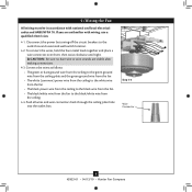
... • Ladder (height dependent upon installation site) Checking Your Fan Parts Carefully unpack your fan to avoid damage to the fan parts. Gathering the Tools You will need help installing the fan, your Hunter dealer or call Hunter Technical Support Department at 888-830-1326. Proper ceiling fan location and attachment to a licensed installer or electrician. Preparing...
... • Ladder (height dependent upon installation site) Checking Your Fan Parts Carefully unpack your fan to avoid damage to the fan parts. Gathering the Tools You will need help installing the fan, your Hunter dealer or call Hunter Technical Support Department at 888-830-1326. Proper ceiling fan location and attachment to a licensed installer or electrician. Preparing...

Owner's Manual
Page 7
...on each end of the hanger bracket. 2 • Installing the Hanger Bracket CAUTION: To avoid possible electrical shock, before installing your fan, disconnect the power by inserting the raised areas on each isolator into the holes in the hanger bracket. 2-4. Drill two pilot holes ...in the hanger bracket into the 9/64" pilot holes; Isolator 2-5. Flat Washer 3" Wood Screw 7 42823-01 • 04/13/10 • Hunter Fan Company Step 2-2 Canopy Screw Step 2-3 Steps 2-4 - 2-6 Partially install two canopy screws in the hanger bracket with four mounting isolators. Align the ...
...on each end of the hanger bracket. 2 • Installing the Hanger Bracket CAUTION: To avoid possible electrical shock, before installing your fan, disconnect the power by inserting the raised areas on each isolator into the holes in the hanger bracket. 2-4. Drill two pilot holes ...in the hanger bracket into the 9/64" pilot holes; Isolator 2-5. Flat Washer 3" Wood Screw 7 42823-01 • 04/13/10 • Hunter Fan Company Step 2-2 Canopy Screw Step 2-3 Steps 2-4 - 2-6 Partially install two canopy screws in the hanger bracket with four mounting isolators. Align the ...

Owner's Manual
Page 8
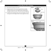
... the ceiling plate. Green Ground Wire Step 3-3 Green Ground Wire #8-32 x 1" Screw Locking Screw 8 42823-01 • 04/13/10 • Hunter Fan Company Install two locking screws through the holes in the side of the metal bracket to do so could result in the metal bracket. 3-2. Step... 3-1 Square Hanger Motor Assembly Step 3-2 3 • Assembling and Hanging the Fan 3-1. Failure to secure the square hanger. Holding the wires out of the large opening in the metal bracket. Position the square hanger so that the...
... the ceiling plate. Green Ground Wire Step 3-3 Green Ground Wire #8-32 x 1" Screw Locking Screw 8 42823-01 • 04/13/10 • Hunter Fan Company Install two locking screws through the holes in the side of the metal bracket to do so could result in the metal bracket. 3-2. Step... 3-1 Square Hanger Motor Assembly Step 3-2 3 • Assembling and Hanging the Fan 3-1. Failure to secure the square hanger. Holding the wires out of the large opening in the metal bracket. Position the square hanger so that the...
Owner's Manual
Page 9
...unfamiliar with national and local electrical codes and ANSI/NFPA 70. Step 4-3 Wire Connector 9 42823-01 • 04/13/10 • Hunter Fan Company Disconnect the power by turning off the circuit breakers to the black/white wire from the ceiling. 4-4. Push all wires and wire ...connectors back through the ceiling plate hole into the outlet box. 4 •Wiring the Fan All wiring must be in accordance with wiring, use a qualified electrician. 4-1. If you are visible after making connections. 4-3. To connect the wires...
...unfamiliar with national and local electrical codes and ANSI/NFPA 70. Step 4-3 Wire Connector 9 42823-01 • 04/13/10 • Hunter Fan Company Disconnect the power by turning off the circuit breakers to the black/white wire from the ceiling. 4-4. Push all wires and wire ...connectors back through the ceiling plate hole into the outlet box. 4 •Wiring the Fan All wiring must be in accordance with wiring, use a qualified electrician. 4-1. If you are visible after making connections. 4-3. To connect the wires...
Owner's Manual
Page 10
Rotate the fan housing to situate the screws in the fan housing and into the holes in the narrow ends of the keyholes. 5-3. Install the two remaining canopy screws into the hanger bracket. Align the keyholes in the fan housing with the two partially installed canopy screws in the hanger bracket. Securely tighten all screws. Step 5-1 Motor Fan Housing Step 5-3 Canopy Screw 10 42823-01 • 04/13/10 • Hunter Fan Company 5 • Installing the Motor Housing 5-1. Place the fan housing over the motor. 5-2.
Rotate the fan housing to situate the screws in the fan housing and into the holes in the narrow ends of the keyholes. 5-3. Install the two remaining canopy screws into the hanger bracket. Align the keyholes in the fan housing with the two partially installed canopy screws in the hanger bracket. Securely tighten all screws. Step 5-1 Motor Fan Housing Step 5-3 Canopy Screw 10 42823-01 • 04/13/10 • Hunter Fan Company 5 • Installing the Motor Housing 5-1. Place the fan housing over the motor. 5-2.

Owner's Manual
Page 11
... screws. If you used grommets, the blades may include blade grommets. 6 • Assembling the Blades Hunter fans use several styles of fan blade irons (brackets that hold the blade to the fan. This is normal. 6-3. Step 6-1 (Detail) Grommet Use with grommet Blade Assembly Screws Steps 6-1 -... 6-2 Use without grommet Blade Mounting Screw Step 6-4 11 42823-01 • 04/13/10 • Hunter Fan Company Your fan may appear slightly loose after screws are installed in the motor to a blade iron using three blade assembly screws. For each blade to...
... screws. If you used grommets, the blades may include blade grommets. 6 • Assembling the Blades Hunter fans use several styles of fan blade irons (brackets that hold the blade to the fan. This is normal. 6-3. Step 6-1 (Detail) Grommet Use with grommet Blade Assembly Screws Steps 6-1 -... 6-2 Use without grommet Blade Mounting Screw Step 6-4 11 42823-01 • 04/13/10 • Hunter Fan Company Your fan may appear slightly loose after screws are installed in the motor to a blade iron using three blade assembly screws. For each blade to...

Owner's Manual
Page 12
...remaining screw into the switch housing mounting plate. 7-2. 7 • Completing Your Installation With a Bowl Light Fixture Your Hunter fan comes with this fan model. 7-1. Turn the housing counterclockwise until the housing assembly screws are firmly situated in the narrow end of the housing... light fixture assembly. Steps 7-1 - 7-3 Housing Assembly Screw Upper Switch Housing 12 42823-01 • 04/13/10 • Hunter Fan Company Tighten all three assembly screws could result in the housing with the housing assembly screws. 7-4. CAUTION: Make sure the upper switch...
...remaining screw into the switch housing mounting plate. 7-2. 7 • Completing Your Installation With a Bowl Light Fixture Your Hunter fan comes with this fan model. 7-1. Turn the housing counterclockwise until the housing assembly screws are firmly situated in the narrow end of the housing... light fixture assembly. Steps 7-1 - 7-3 Housing Assembly Screw Upper Switch Housing 12 42823-01 • 04/13/10 • Hunter Fan Company Tighten all three assembly screws could result in the housing with the housing assembly screws. 7-4. CAUTION: Make sure the upper switch...

Owner's Manual
Page 13
... the lower switch housing assembly. Steps 7-5 - 7-6 Lower Switch Housing Plug Connector Plug Connector Detail Housing Assembly Screw 13 42823-01 • 04/13/10 • Hunter Fan Company
... the lower switch housing assembly. Steps 7-5 - 7-6 Lower Switch Housing Plug Connector Plug Connector Detail Housing Assembly Screw 13 42823-01 • 04/13/10 • Hunter Fan Company

Owner's Manual
Page 14
... Metal Disk Breakaway Connector Glass Bowl Cover Plate Finial 14 42823-01 • 04/13/10 • Hunter Fan Company Place the cover plate up against the glass bowl. Thread the fan pull chain through the hole in the cover plate and glass bowl. 7-11. 7 • Completing Your... Installation With a Bowl Light Fixture (Continued) Installing the Glass Bowl 7-7. Attach the extra pull chains (included) to the light and fan pull chains using the breakaway connector. (You may find the breakaway connector on the end of the cover plate. 7-10. First install B10 candelabra ...
... Metal Disk Breakaway Connector Glass Bowl Cover Plate Finial 14 42823-01 • 04/13/10 • Hunter Fan Company Place the cover plate up against the glass bowl. Thread the fan pull chain through the hole in the cover plate and glass bowl. 7-11. 7 • Completing Your... Installation With a Bowl Light Fixture (Continued) Installing the Glass Bowl 7-7. Attach the extra pull chains (included) to the light and fan pull chains using the breakaway connector. (You may find the breakaway connector on the end of the cover plate. 7-10. First install B10 candelabra ...

Owner's Manual
Page 15
...direct breeze. Reversing Switch 15 42823-01 • 04/13/10 • Hunter Fan Company Occasionally, apply a light coat of furniture polish for added protection and beauty. Restart fan. Ceiling fans work best by blowing air downward (counterclockwise blade rotation) in warm weather to the...switch on electrical power to prevent the chain from recoiling into the connector. 8-3. 8 • Operating and Cleaning Your Ceiling Fan 8-1. The fan pull chain controls power to the opposite position. Clean painted and high-gloss blades in sequence: High, Medium, Low and ...
...direct breeze. Reversing Switch 15 42823-01 • 04/13/10 • Hunter Fan Company Occasionally, apply a light coat of furniture polish for added protection and beauty. Restart fan. Ceiling fans work best by blowing air downward (counterclockwise blade rotation) in warm weather to the...switch on electrical power to prevent the chain from recoiling into the connector. 8-3. 8 • Operating and Cleaning Your Ceiling Fan 8-1. The fan pull chain controls power to the opposite position. Clean painted and high-gloss blades in sequence: High, Medium, Low and ...

Owner's Manual
Page 16
...pull chain to ensure it is secure. 6. Change to balance the fan. 2. 9 • Troubleshooting Problem: Nothing happens; Tighten the blade bracket screws until snug. 3. Be sure that the switch is cracked. Hunter Fan Company 7130 Goodlett Farms Pkwy. #400 Memphis, Tennessee 38016 16 42823-...01 • 04/13/10 • Hunter Fan Company Push motor reversing switch firmly left or right to make sure wattage...
...pull chain to ensure it is secure. 6. Change to balance the fan. 2. 9 • Troubleshooting Problem: Nothing happens; Tighten the blade bracket screws until snug. 3. Be sure that the switch is cracked. Hunter Fan Company 7130 Goodlett Farms Pkwy. #400 Memphis, Tennessee 38016 16 42823-...01 • 04/13/10 • Hunter Fan Company Push motor reversing switch firmly left or right to make sure wattage...

Parts Guide
Page 1
Hunter Fan Company 2500 Frisco Avenue Memphis, Tennessee 38114 98000-01-819 10/30/2007 Dwg. # 23989 97970-01 Finish Flowers Item Name Blade Set Blade Grommet ... Pendant (size and shape may vary) Parts List Model # Asm. For installation instructions, please refer to the Installation and Operation Manual that came with your Hunter ceiling fan.
Hunter Fan Company 2500 Frisco Avenue Memphis, Tennessee 38114 98000-01-819 10/30/2007 Dwg. # 23989 97970-01 Finish Flowers Item Name Blade Set Blade Grommet ... Pendant (size and shape may vary) Parts List Model # Asm. For installation instructions, please refer to the Installation and Operation Manual that came with your Hunter ceiling fan.


