
Installation Guide
Page 1
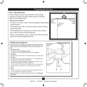
... Cut a 4" diameter hole through the inner holes of the fan blade tips. • e fan is suitable, go to your new Hunter fan. Step 4 Step 4 Install the Outlet Box 4-1. You will hold full weight of the fan and light kit. Step 5 Step 5 Prepare the Wiring ...ceiling is recessed a minimum of 1/16" into ceiling. o e bottom of the ceiling. Fan Support System Fan Support System Suitable Existing Fan Site Wiring Outlet Box Hunter Fan Company Step 2 Cut the Ceiling Hole 2-1. Make certain the wiring meets all national and local standards ...
... Cut a 4" diameter hole through the inner holes of the fan blade tips. • e fan is suitable, go to your new Hunter fan. Step 4 Step 4 Install the Outlet Box 4-1. You will hold full weight of the fan and light kit. Step 5 Step 5 Prepare the Wiring ...ceiling is recessed a minimum of 1/16" into ceiling. o e bottom of the ceiling. Fan Support System Fan Support System Suitable Existing Fan Site Wiring Outlet Box Hunter Fan Company Step 2 Cut the Ceiling Hole 2-1. Make certain the wiring meets all national and local standards ...

Owner's Manual
Page 1
Model Name Model No. Date Purchased Where Purchased Type 2 Models Owner's Guide and Installation Manual English Español Form# 42433-01 20111119 ©2011 Hunter Fan Co. For Your Records and Warranty Assistance For reference, also attach your receipt or a copy of your receipt to the manual.
Model Name Model No. Date Purchased Where Purchased Type 2 Models Owner's Guide and Installation Manual English Español Form# 42433-01 20111119 ©2011 Hunter Fan Co. For Your Records and Warranty Assistance For reference, also attach your receipt or a copy of your receipt to the manual.

Owner's Manual
Page 2
... This product conforms to UL STD 507 and is complete. © 2011 Hunter Fan Company 2 42433-01 • 01/19/11 • Hunter Fan Company Before installing your fan, for many years. Never insert foreign objects between rotating fan blades. • To reduce the risk of the building according to these ...shock, or motor damage, do not bend the blade attachment system when installing, balancing, or cleaning the fan. Welcome Your new Hunter® ceiling fan is an addition to your fan installation is certified to STD C22.2 No.113 • Wash your hands after your home or office ...
... This product conforms to UL STD 507 and is complete. © 2011 Hunter Fan Company 2 42433-01 • 01/19/11 • Hunter Fan Company Before installing your fan, for many years. Never insert foreign objects between rotating fan blades. • To reduce the risk of the building according to these ...shock, or motor damage, do not bend the blade attachment system when installing, balancing, or cleaning the fan. Welcome Your new Hunter® ceiling fan is an addition to your fan installation is certified to STD C22.2 No.113 • Wash your hands after your home or office ...
Owner's Manual
Page 3
... below the joist or support brace. Choose the Fan Site Proper ceiling fan location and attachment to Section 2 • Installing the Ceiling Plate. Fan Support System Fan Support System Suitable Existing Fan Site Wiring Outlet Box 3 42433-01 • 01/19/11 • Hunter Fan Company If your new Hunter fan. Choose a fan site where: • No object can come...
... below the joist or support brace. Choose the Fan Site Proper ceiling fan location and attachment to Section 2 • Installing the Ceiling Plate. Fan Support System Fan Support System Suitable Existing Fan Site Wiring Outlet Box 3 42433-01 • 01/19/11 • Hunter Fan Company If your new Hunter fan. Choose a fan site where: • No object can come...

Owner's Manual
Page 4
... with Section 2 • Installing the Ceiling Plate. Cut the Ceiling Hole 2-1. Steps 2 - 3 3-2. Make sure the circuit breakers to the fan supply line leads and associated wall switch location are unfamiliar with wiring, use the hole to the outlet box with the joist or support brace...electrical supply house. 4-2. You will use a qualified electrician. 4 42433-01 • 01/19/11 • Hunter Fan Company If the joist is there, determine if it will hold the outlet box and fan. 2-2. If NOT, install a support brace as a tag, to recess the bottom of the outlet box a...
... with Section 2 • Installing the Ceiling Plate. Cut the Ceiling Hole 2-1. Steps 2 - 3 3-2. Make sure the circuit breakers to the fan supply line leads and associated wall switch location are unfamiliar with wiring, use the hole to the outlet box with the joist or support brace...electrical supply house. 4-2. You will use a qualified electrician. 4 42433-01 • 01/19/11 • Hunter Fan Company If the joist is there, determine if it will hold the outlet box and fan. 2-2. If NOT, install a support brace as a tag, to recess the bottom of the outlet box a...
Owner's Manual
Page 5
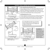
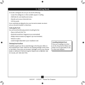
... of three ways, depending on ceiling height and your Hunter fan, use only Hunter speed controls. Understanding Mounting and Installer's Choice® Hunter's patented 3-position mounting system provides you can install your Hunter fan in this manual include instructions for ceilings less than ... recommended for all three Installer's Choice mounting methods. Considering Optional Accessories Consider using Hunter's optional accessories, including a wall-mounted or remote speed control. All Hunter fans use sturdy 3/4" diameter pipe to these instructions, and use the accessories, follow ...
... of three ways, depending on ceiling height and your Hunter fan, use only Hunter speed controls. Understanding Mounting and Installer's Choice® Hunter's patented 3-position mounting system provides you can install your Hunter fan in this manual include instructions for ceilings less than ... recommended for all three Installer's Choice mounting methods. Considering Optional Accessories Consider using Hunter's optional accessories, including a wall-mounted or remote speed control. All Hunter fans use sturdy 3/4" diameter pipe to these instructions, and use the accessories, follow ...
Owner's Manual
Page 6
... pliers • Ladder (height dependent upon installation site) Checking Your Fan Parts Carefully unpack your fan to avoid damage to the fan parts. Refer to the included Parts Guide. If you are missing or damaged, contact your Hunter fan dealer can direct you can do the following tools for any parts ...are installing more than one fan, keep the fan blades and blade irons (if applicable) in ceiling. • Drill holes for and...
... pliers • Ladder (height dependent upon installation site) Checking Your Fan Parts Carefully unpack your fan to avoid damage to the fan parts. Refer to the included Parts Guide. If you are missing or damaged, contact your Hunter fan dealer can direct you can do the following tools for any parts ...are installing more than one fan, keep the fan blades and blade irons (if applicable) in ceiling. • Drill holes for and...

Owner's Manual
Page 7
... in the center of the two 3" wood screws. 2-4. 2 • Installing the Ceiling Plate CAUTION: To avoid possible electrical shock, before installing your fan, disconnect the power by turning off position, securely fasten a prominent warning device, such as a tag, to make sure all four isolators are pointing toward...the wood support structure through the outermost holes in diameter. Ceiling Plate 3" Wood Screw Steps 2-3 - 2-6 7 42433-01 • 01/19/11 • Hunter Fan Company Place a flat washer on the screws. Note: The isolators should be flush against the ceiling. 2-6.
... in the center of the two 3" wood screws. 2-4. 2 • Installing the Ceiling Plate CAUTION: To avoid possible electrical shock, before installing your fan, disconnect the power by turning off position, securely fasten a prominent warning device, such as a tag, to make sure all four isolators are pointing toward...the wood support structure through the outermost holes in diameter. Ceiling Plate 3" Wood Screw Steps 2-3 - 2-6 7 42433-01 • 01/19/11 • Hunter Fan Company Place a flat washer on the screws. Note: The isolators should be flush against the ceiling. 2-6.

Owner's Manual
Page 8
...Low Profile Screw Low Profile Washer 8 42433-01 • 01/19/11 • Hunter Fan Company Hanging the Fan: Note: To hang the fan, you must tilt the canopy to install the pipe and ball assembly. Raise the fan and align the slots in the washer with a wrench or pliers. For Standard or ...position so that the canopy slots sit on one side of the pin in these installation instructions. 3-1. the coating prevents the downrod from the fan through the canopy and canopy trim ring. Once assembled, do not remove the downrod. Insert the downrod through the downrod on the ceiling ...
...Low Profile Screw Low Profile Washer 8 42433-01 • 01/19/11 • Hunter Fan Company Hanging the Fan: Note: To hang the fan, you must tilt the canopy to install the pipe and ball assembly. Raise the fan and align the slots in the washer with a wrench or pliers. For Standard or ...position so that the canopy slots sit on one side of the pin in these installation instructions. 3-1. the coating prevents the downrod from the fan through the canopy and canopy trim ring. Once assembled, do not remove the downrod. Insert the downrod through the downrod on the ceiling ...

Owner's Manual
Page 9
...) for the wall switch Single Switch Wiring: • The black wire (ungrounded) from the ceiling to the white wire (grounded) from the fan CAUTION: Be sure no bare wire or wire strands are not included. Before attempting installation, make sure the power is still off. 4-2. To ... Wall switches are visible after making connections. 4-6. 4 • Wiring the Fan All wiring must be in accordance with the grounded wires on one side of the outlet box. 9 42433-01 • 01/19/11 • Hunter Fan Company Wire Connector Dual Switch Wiring Single Switch Wiring If you are unfamiliar...
...) for the wall switch Single Switch Wiring: • The black wire (ungrounded) from the ceiling to the white wire (grounded) from the fan CAUTION: Be sure no bare wire or wire strands are not included. Before attempting installation, make sure the power is still off. 4-2. To ... Wall switches are visible after making connections. 4-6. 4 • Wiring the Fan All wiring must be in accordance with the grounded wires on one side of the outlet box. 9 42433-01 • 01/19/11 • Hunter Fan Company Wire Connector Dual Switch Wiring Single Switch Wiring If you are unfamiliar...

Owner's Manual
Page 10
... screwdriver for alignment. 5-3. Step 5-1 Tab Groove Step 5-2 Step 5-3 Canopy Canopy Trim Ring Canopy Screw 10 42433-01 • 01/19/11 • Hunter Fan Company Holding the canopy up with the mounting holes on the ceiling plate. Partially install a canopy screw into place. The tabs will snap and lock..., press firmly on opposite sides of the trim ring directly above the groove in the grooves of the hanger ball. 5-6. Note: Your fan may have multiple tabs and grooves that the tabs in the canopy are properly aligned, securely tighten all the holes are still in the...
... screwdriver for alignment. 5-3. Step 5-1 Tab Groove Step 5-2 Step 5-3 Canopy Canopy Trim Ring Canopy Screw 10 42433-01 • 01/19/11 • Hunter Fan Company Holding the canopy up with the mounting holes on the ceiling plate. Partially install a canopy screw into place. The tabs will snap and lock..., press firmly on opposite sides of the trim ring directly above the groove in the grooves of the hanger ball. 5-6. Note: Your fan may have multiple tabs and grooves that the tabs in the canopy are properly aligned, securely tighten all the holes are still in the...
Owner's Manual
Page 11
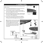
... been treated with grommet Blade Assembly Screws Step 6-4 Use without grommet 11 42433-01 • 01/19/11 • Hunter Fan Company Blade Mounting Screw Attach each blade, insert one blade mounting screw through the blade iron, and attach lightly to a blade iron using ...three blade assembly screws. For each blade to the fan. Steps 6-1 - 6-2 Use with Hunter's Dust Armor protection, making the blades less likely to the fan). 6-1. Do not use several styles of fan blade irons (brackets that leave any other cleaners that hold the blade to attract dust...
... been treated with grommet Blade Assembly Screws Step 6-4 Use without grommet 11 42433-01 • 01/19/11 • Hunter Fan Company Blade Mounting Screw Attach each blade, insert one blade mounting screw through the blade iron, and attach lightly to a blade iron using ...three blade assembly screws. For each blade to the fan. Steps 6-1 - 6-2 Use with Hunter's Dust Armor protection, making the blades less likely to the fan). 6-1. Do not use several styles of fan blade irons (brackets that leave any other cleaners that hold the blade to attract dust...

Owner's Manual
Page 12
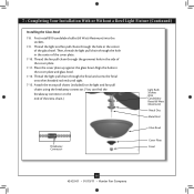
... fixture, proceed with OR without the included light fixture. 7 • Completing Your Installation With or Without a Bowl Light Fixture Your Hunter fan comes with the housing assembly screws. 7-4. This feature gives you the option of the housing. 7-3. Feed the upper plug connector through ...switch housing mounting plate. 7-2. Steps 7-1 - 7-3 Housing Assembly Screw Upper Switch Housing 12 42433-01 • 01/19/11 • Hunter Fan Company Once you want to properly attach and tighten all three screws firmly. Failure to install the light fixture, you are firmly situated in...
... fixture, proceed with OR without the included light fixture. 7 • Completing Your Installation With or Without a Bowl Light Fixture Your Hunter fan comes with the housing assembly screws. 7-4. This feature gives you the option of the housing. 7-3. Feed the upper plug connector through ...switch housing mounting plate. 7-2. Steps 7-1 - 7-3 Housing Assembly Screw Upper Switch Housing 12 42433-01 • 01/19/11 • Hunter Fan Company Once you want to properly attach and tighten all three screws firmly. Failure to install the light fixture, you are firmly situated in...

Owner's Manual
Page 13
... section. Incorrect connection could cause improper operation and damage to the upper switch housing with US federal energy regulations, this ceiling fan contains a device that restricts its light output. Attach the lower switch housing to the product. 7-7. Exceeding the wattage limit marked... one way. Lower Switch Housing Plug Connector Steps 7-6 - 7-7 Plug Connector Detail 13 42433-01 • 01/19/11 • Hunter Fan Company Housing Assembly Screw Align the side screw holes in fire hazard or improper operation. Note: In compliance with three housing assembly screws. ...
... section. Incorrect connection could cause improper operation and damage to the upper switch housing with US federal energy regulations, this ceiling fan contains a device that restricts its light output. Attach the lower switch housing to the product. 7-7. Exceeding the wattage limit marked... one way. Lower Switch Housing Plug Connector Steps 7-6 - 7-7 Plug Connector Detail 13 42433-01 • 01/19/11 • Hunter Fan Company Housing Assembly Screw Align the side screw holes in fire hazard or improper operation. Note: In compliance with three housing assembly screws. ...
Owner's Manual
Page 14
...60 Watt Maximum) Metal Disc Metal Rod Glass Bowl Breakaway Connector Cover Plate Finial 14 42433-01 • 01/19/11 • Hunter Fan Company Thread the light and fan pull chains through the finial and screw the finial onto the threaded rod end until tight. 7-13. Thread the light pull chain ...through the hole in the cover plate and glass bowl. 7-12. Attach the extra pull chains (included) to the light and fan pull chains using the breakaway connector. (You can find the breakaway connector on the end of the glass bowl. 7 • Completing Your Installation With...
...60 Watt Maximum) Metal Disc Metal Rod Glass Bowl Breakaway Connector Cover Plate Finial 14 42433-01 • 01/19/11 • Hunter Fan Company Thread the light and fan pull chains through the finial and screw the finial onto the threaded rod end until tight. 7-13. Thread the light pull chain ...through the hole in the cover plate and glass bowl. 7-12. Attach the extra pull chains (included) to the light and fan pull chains using the breakaway connector. (You can find the breakaway connector on the end of the glass bowl. 7 • Completing Your Installation With...

Owner's Manual
Page 15
... housing. Lower Switch Housing Step 7-16 Male Dummy Terminal Female Dummy Terminal Cap Plug Button Step 7-19 15 42433-01 • 01/19/11 • Hunter Fan Company Remove the light fixture from the lower switch housing, pulling disconnected wires through the hole. 7-18. Disconnect the plug connectors between the black wire...
... housing. Lower Switch Housing Step 7-16 Male Dummy Terminal Female Dummy Terminal Cap Plug Button Step 7-19 15 42433-01 • 01/19/11 • Hunter Fan Company Remove the light fixture from the lower switch housing, pulling disconnected wires through the hole. 7-18. Disconnect the plug connectors between the black wire...
Owner's Manual
Page 16
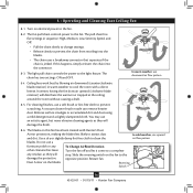
... Dust Armor on electrical power to the light fixture. For cleaning finishes, use a soft brush or lint-free cloth to cool the room with Hunter's Dust Armor protection, making the blades less likely to the opposite position. A vacuum cleaner brush nozzle can remove heavier dust. In warm weather,... use upward air flow pattern 16 42433-01 • 01/19/11 • Hunter Fan Company Do not use an artistic agent, but never abrasive cleaning agents as they will distribute the warmer air trapped at the ceiling around the...
... Dust Armor on electrical power to the light fixture. For cleaning finishes, use a soft brush or lint-free cloth to cool the room with Hunter's Dust Armor protection, making the blades less likely to the opposite position. A vacuum cleaner brush nozzle can remove heavier dust. In warm weather,... use upward air flow pattern 16 42433-01 • 01/19/11 • Hunter Fan Company Do not use an artistic agent, but never abrasive cleaning agents as they will distribute the warmer air trapped at the ceiling around the...

Owner's Manual
Page 17
... so, replace all blade iron screws. 3. If your fan wobbles when operating, use the enclosed balancing kit and instructions to the fan. Problem: CFL bulbs flicker when controlled by a dimming remote or wall control 1. Hunter Fan Company 7130 Goodlett Farms Parkway #400 Memphis, Tennessee 38016 ...17 42433-01 • 01/19/11 • Hunter Fan Company Turn power on the MAX...
... so, replace all blade iron screws. 3. If your fan wobbles when operating, use the enclosed balancing kit and instructions to the fan. Problem: CFL bulbs flicker when controlled by a dimming remote or wall control 1. Hunter Fan Company 7130 Goodlett Farms Parkway #400 Memphis, Tennessee 38016 ...17 42433-01 • 01/19/11 • Hunter Fan Company Turn power on the MAX...

Parts Guide
Page 1
...65666-01 1 G0090-01 1 G0091-01 1 63756-47 2 63756-56 1 08198-01 1 08200-01 1 73853-01 1 73854-01 2 77646-08 Hunter Fan Company • 7130 Goodlett Farms Pkwy. #400 • Memphis, TN 38016 • www.hunterfan.com • 98000-02-039 05-26-2010 •... Pull Chain Pendant Pull Chain Pendant Pull Chain Pull Chain Dummy Terminal, Male Dummy Terminal, Female Cap, Switch Housing Plug Button Light bulb / Bulb Model # 28670 Asm. Hardware (Drawn to Scale) x 1 x 2 x 4 x 2 x 3 x 4 x 1 x 4 Balancing x 1 Kit Wire x 4 Connector x 11 x 16 x 16 x 3 x 3 Low Profile Washer 3"...
...65666-01 1 G0090-01 1 G0091-01 1 63756-47 2 63756-56 1 08198-01 1 08200-01 1 73853-01 1 73854-01 2 77646-08 Hunter Fan Company • 7130 Goodlett Farms Pkwy. #400 • Memphis, TN 38016 • www.hunterfan.com • 98000-02-039 05-26-2010 •... Pull Chain Pendant Pull Chain Pendant Pull Chain Pull Chain Dummy Terminal, Male Dummy Terminal, Female Cap, Switch Housing Plug Button Light bulb / Bulb Model # 28670 Asm. Hardware (Drawn to Scale) x 1 x 2 x 4 x 2 x 3 x 4 x 1 x 4 Balancing x 1 Kit Wire x 4 Connector x 11 x 16 x 16 x 3 x 3 Low Profile Washer 3"...


