
Owner's Manual
Page 1
Date Purchased Where Purchased Type 2 Models Owner's Guide and Installation Manual English Español Form# 42443-01 20100920 ©2010 Hunter Fan Co. Model Name Model No. For Your Records and Warranty Assistance For reference, also attach your receipt or a copy of your receipt to the manual.
Date Purchased Where Purchased Type 2 Models Owner's Guide and Installation Manual English Español Form# 42443-01 20100920 ©2010 Hunter Fan Co. Model Name Model No. For Your Records and Warranty Assistance For reference, also attach your receipt or a copy of your receipt to the manual.
Owner's Manual
Page 2
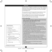
.... © 2010 Hunter Fan Company 2 42443-01 • 09/20/10 • Hunter Fan Company Table Of Contents Preparing the Fan Site 3 1 • Getting Ready 6 2 • Installing the Ceiling Plate 7 3 • Assembling and Hanging the Fan . . . . 8 4 • Wiring the Fan 9 5 • Installing the Canopy and Canopy Trim Ring 10 6 • Assembling the Blades 11 7 • Completing Your Installation With or Without a Bowl Light Fixture 12 8 • Operating and Cleaning Your Ceiling Fan 16 9 • Troubleshooting 17 Welcome Your new Hunter® ceiling fan is an...
.... © 2010 Hunter Fan Company 2 42443-01 • 09/20/10 • Hunter Fan Company Table Of Contents Preparing the Fan Site 3 1 • Getting Ready 6 2 • Installing the Ceiling Plate 7 3 • Assembling and Hanging the Fan . . . . 8 4 • Wiring the Fan 9 5 • Installing the Canopy and Canopy Trim Ring 10 6 • Assembling the Blades 11 7 • Completing Your Installation With or Without a Bowl Light Fixture 12 8 • Operating and Cleaning Your Ceiling Fan 16 9 • Troubleshooting 17 Welcome Your new Hunter® ceiling fan is an...

Owner's Manual
Page 3
... 30 inches of the fan and light kit. Outlet Box • e outlet box is an UL-approved octagonal 4" x 1-1/2" outlet box (or as described on this page. Wiring • e electrical cable is recessed a minimum of lead wires extend from outlet box. Fan Support System Fan Support System Suitable Existing Fan Site Wiring Outlet Box 3 42443-01 • 09/20/10 • Hunter Fan Company Ceiling Hole • e outlet box clearance hole is suitable...
... 30 inches of the fan and light kit. Outlet Box • e outlet box is an UL-approved octagonal 4" x 1-1/2" outlet box (or as described on this page. Wiring • e electrical cable is recessed a minimum of lead wires extend from outlet box. Fan Support System Fan Support System Suitable Existing Fan Site Wiring Outlet Box 3 42443-01 • 09/20/10 • Hunter Fan Company Ceiling Hole • e outlet box clearance hole is suitable...

Owner's Manual
Page 4
... ceiling. You will use a qualified electrician. 4 42443-01 • 09/20/10 • Hunter Fan Company If NOT, install a support brace as a tag, to recess the outlet box a minimum of the fan and light kit. Position it will hold the outlet box and fan. 2-2. Obtain a UL-approved octagonal 4" x 1-1/2" outlet box, plus two #8 x 1-1/2" wood screws and washers, available from any hardware store or electrical supply house. 5-4. Step 5 - Prepare the Wiring...
... ceiling. You will use a qualified electrician. 4 42443-01 • 09/20/10 • Hunter Fan Company If NOT, install a support brace as a tag, to recess the outlet box a minimum of the fan and light kit. Position it will hold the outlet box and fan. 2-2. Obtain a UL-approved octagonal 4" x 1-1/2" outlet box, plus two #8 x 1-1/2" wood screws and washers, available from any hardware store or electrical supply house. 5-4. Step 5 - Prepare the Wiring...

Owner's Manual
Page 5
... can purchase Hunter extension downrods. Considering Optional Accessories Consider using Hunter's optional accessories, including a wall-mounted or remote speed control. All Hunter fans use only the hardware supplied. 5 42443-01 • 09/20/10 • Hunter Fan Company For quiet and optimum performance of three ways, depending on ceiling height and your preference: Low Profile, Standard, or Angled mounting. Angled Mounting Style 8 12 Angled Mounting recommended for a vaulted or angled ceiling Support Brace Low Profile Mounting Style Ceiling Outlet Box Low Profile Mounting fits...
... can purchase Hunter extension downrods. Considering Optional Accessories Consider using Hunter's optional accessories, including a wall-mounted or remote speed control. All Hunter fans use only the hardware supplied. 5 42443-01 • 09/20/10 • Hunter Fan Company For quiet and optimum performance of three ways, depending on ceiling height and your preference: Low Profile, Standard, or Angled mounting. Angled Mounting Style 8 12 Angled Mounting recommended for a vaulted or angled ceiling Support Brace Low Profile Mounting Style Ceiling Outlet Box Low Profile Mounting fits...

Owner's Manual
Page 6
... install wood screws. • Identify and connect electrical wires. • Lift 40 pounds. Installing Multiple Fans? 1 • Getting Ready To install a ceiling fan, be sure you can direct you are missing or damaged, contact your fan to avoid damage to the fan parts. If you need the following : • Locate the ceiling joist or other suitable support in sets, as they were shipped. 6 42443-01 • 09/20/10 • Hunter Fan Company...
... install wood screws. • Identify and connect electrical wires. • Lift 40 pounds. Installing Multiple Fans? 1 • Getting Ready To install a ceiling fan, be sure you can direct you are missing or damaged, contact your fan to avoid damage to the fan parts. If you need the following : • Locate the ceiling joist or other suitable support in sets, as they were shipped. 6 42443-01 • 09/20/10 • Hunter Fan Company...

Owner's Manual
Page 7
2 • Installing the Ceiling Plate CAUTION: To avoid possible electrical shock, before installing your fan, disconnect the power by turning off position, securely fasten a prominent warning device, such as a tag, to the service panel. 2-1. Flat Washer Toward Ceiling Peak For Angled Ceilings: Be sure to the outlet box and associated wall switch location. For Angled Ceilings: Be sure to make sure all four isolators are in the center...
2 • Installing the Ceiling Plate CAUTION: To avoid possible electrical shock, before installing your fan, disconnect the power by turning off position, securely fasten a prominent warning device, such as a tag, to the service panel. 2-1. Flat Washer Toward Ceiling Peak For Angled Ceilings: Be sure to the outlet box and associated wall switch location. For Angled Ceilings: Be sure to make sure all four isolators are in the center...

Owner's Manual
Page 8
... When the pipe and ball assembly is replaced with the holes in the ball. 3-3. Align the holes in the washer with the low profile washer. 3-4. Standard or Angled Mounting Steps 3-2 - 3-3 Downrod Setscrew Canopy Canopy Trim Ring Low Profile Mounting Steps 3-5 - 3-6 Low Profile Screws Green Ground Wire Canopy Trim Ring Low Profile Washer Canopy Low Profile Screw Step 3-6 (Detail) Adapter Low Profile Screw Low Profile Washer 8 42443-01 • 09/20/10 • Hunter Fan Company Once assembled, do not remove the downrod. CAUTION: The adapter has a special coating on...
... When the pipe and ball assembly is replaced with the holes in the ball. 3-3. Align the holes in the washer with the low profile washer. 3-4. Standard or Angled Mounting Steps 3-2 - 3-3 Downrod Setscrew Canopy Canopy Trim Ring Low Profile Mounting Steps 3-5 - 3-6 Low Profile Screws Green Ground Wire Canopy Trim Ring Low Profile Washer Canopy Low Profile Screw Step 3-6 (Detail) Adapter Low Profile Screw Low Profile Washer 8 42443-01 • 09/20/10 • Hunter Fan Company Once assembled, do not remove the downrod. CAUTION: The adapter has a special coating on...

Owner's Manual
Page 9
... the outlet box. 9 42443-01 • 09/20/10 • Hunter Fan Company Wire Connector Dual Switch Wiring Single Switch Wiring Before attempting installation, make sure the power is still off. 4-2. Connect the white wire (grounded) from the ceiling to the black (ungrounded) and the black/white wire (ungrounded) from the fan CAUTION: Be sure no bare wire or wire strands are not included. If you are unfamiliar with wiring, use the wire connectors provided. 4-3. Wall switches are...
... the outlet box. 9 42443-01 • 09/20/10 • Hunter Fan Company Wire Connector Dual Switch Wiring Single Switch Wiring Before attempting installation, make sure the power is still off. 4-2. Connect the white wire (grounded) from the ceiling to the black (ungrounded) and the black/white wire (ungrounded) from the fan CAUTION: Be sure no bare wire or wire strands are not included. If you are unfamiliar with wiring, use the wire connectors provided. 4-3. Wall switches are...

Owner's Manual
Page 10
... secure in the grooves of the hanger ball. 5-6. Holding the canopy up with the mounting holes on the ceiling plate. Using both hands, push the canopy trim ring up to align the canopy screw holes with the screw holes aligned, partially install two canopy screws into the holes opposite the ceiling plate tabs. 5-4. 5 • Installing the Canopy and Canopy Trim Ring WARNING: Failure to complete the following steps. Note: Your fan may have multiple tabs and grooves...
... secure in the grooves of the hanger ball. 5-6. Holding the canopy up with the mounting holes on the ceiling plate. Using both hands, push the canopy trim ring up to align the canopy screw holes with the screw holes aligned, partially install two canopy screws into the holes opposite the ceiling plate tabs. 5-4. 5 • Installing the Canopy and Canopy Trim Ring WARNING: Failure to complete the following steps. Note: Your fan may have multiple tabs and grooves...

Owner's Manual
Page 11
... residue, as they are installed. Do not blades. protective Dust Armor on this fan have been treated with a protective cloth to prevent scratching the to the blade iron and the flared tops of the blade. Cover the blade iron posts with Hunter's Dust Armor protection, making the blades less likely to Blade remove the blades easily for cleaning. 6-1. Using pliers, loosen the blade iron posts by turning them...
... residue, as they are installed. Do not blades. protective Dust Armor on this fan have been treated with a protective cloth to prevent scratching the to the blade iron and the flared tops of the blade. Cover the blade iron posts with Hunter's Dust Armor protection, making the blades less likely to Blade remove the blades easily for cleaning. 6-1. Using pliers, loosen the blade iron posts by turning them...

Owner's Manual
Page 12
... light fixture, proceed with the enclosed light kit. WARNING: Use only the light fixture supplied with Step 7‑1. 12 42443-01 • 09/20/10 • Hunter Fan Company CAUTION: Make sure the upper switch housing is to properly attach and tighten all three assembly screws could result in improper performance of installing the fan with an integrated light fixture assembly and an optional switch housing cap and plug button. See "Uninstalling the Light Fixture...
... light fixture, proceed with the enclosed light kit. WARNING: Use only the light fixture supplied with Step 7‑1. 12 42443-01 • 09/20/10 • Hunter Fan Company CAUTION: Make sure the upper switch housing is to properly attach and tighten all three assembly screws could result in improper performance of installing the fan with an integrated light fixture assembly and an optional switch housing cap and plug button. See "Uninstalling the Light Fixture...

Owner's Manual
Page 13
... Lower Switch Housing Steps 7-3 - 7-5 13 42443-01 • 09/20/10 • Hunter Fan Company Note: Both plug connectors are properly aligned before connecting them. Tighten all three screws securely. Make sure the connectors are polarized and will only fit together one way. Steps 7-1 - 7-2 Housing Assembly Screw 7-4. Connect the upper plug connector from the motor to the fan, partially install two housing assembly screws into the upper switch housing. 7-2. 7 • Completing Your Installation With or Without a Bowl Light Fixture (Continued...
... Lower Switch Housing Steps 7-3 - 7-5 13 42443-01 • 09/20/10 • Hunter Fan Company Note: Both plug connectors are properly aligned before connecting them. Tighten all three screws securely. Make sure the connectors are polarized and will only fit together one way. Steps 7-1 - 7-2 Housing Assembly Screw 7-4. Connect the upper plug connector from the motor to the fan, partially install two housing assembly screws into the upper switch housing. 7-2. 7 • Completing Your Installation With or Without a Bowl Light Fixture (Continued...

Owner's Manual
Page 14
... of the glass bowl. Thread the light and fan pull chains through the grommet hole in the center of the extra chain.) For Light Bulbs Metal Disc Metal Rod Breakaway Connector Glass Bowl Cover Plate Finial 14 42443-01 • 09/20/10 • Hunter Fan Company Place the cover plate up against the glass bowl. Thread the fan pull chain through the hole in the side of the cover plate. 7-8. Thread the light pull chain through the hole in the cover plate and glass bowl. 7-10. Align...
... of the glass bowl. Thread the light and fan pull chains through the grommet hole in the center of the extra chain.) For Light Bulbs Metal Disc Metal Rod Breakaway Connector Glass Bowl Cover Plate Finial 14 42443-01 • 09/20/10 • Hunter Fan Company Place the cover plate up against the glass bowl. Thread the fan pull chain through the hole in the side of the cover plate. 7-8. Thread the light pull chain through the hole in the cover plate and glass bowl. 7-10. Align...

Owner's Manual
Page 15
...8226; 09/20/10 • Hunter Fan Company Remove the light fixture from the lower switch housing, pulling disconnected wires through the hole. 7-16. Remove the two screws attaching the light kit to the lower switch housing. 7-18. Lower Switch Housing 7-15. 7 • Completing Your Installation With or Without a Bowl Light Fixture (Continued) Uninstalling the Light Fixture 7-12. To uninstall the light fixture, first disconnect the plug connectors between the two white wires. 7-14. Install the switch housing cap and plug button to the lower switch housing.
...8226; 09/20/10 • Hunter Fan Company Remove the light fixture from the lower switch housing, pulling disconnected wires through the hole. 7-16. Remove the two screws attaching the light kit to the lower switch housing. 7-18. Lower Switch Housing 7-15. 7 • Completing Your Installation With or Without a Bowl Light Fixture (Continued) Uninstalling the Light Fixture 7-12. To uninstall the light fixture, first disconnect the plug connectors between the two white wires. 7-14. Install the switch housing cap and plug button to the lower switch housing.

Owner's Manual
Page 16
... been treated with a direct breeze. For cleaning finishes, use downward air flow pattern 8-5. Restart fan. The light pull chain controls the power to a complete stop. Ceiling fans work best by blowing air downward (counterclockwise blade rotation) in sequence: High, Medium, Low, and Off. • Pull the chain slowly to change settings. • Release slowly to the fan. 8-2. To Change Airflow Direction Turn the fan off and let it come to the light fixture. Turn on the blades. 8 • Operating and Cleaning Your Ceiling Fan 8-1.
... been treated with a direct breeze. For cleaning finishes, use downward air flow pattern 8-5. Restart fan. The light pull chain controls the power to a complete stop. Ceiling fans work best by blowing air downward (counterclockwise blade rotation) in sequence: High, Medium, Low, and Off. • Pull the chain slowly to change settings. • Release slowly to the fan. 8-2. To Change Airflow Direction Turn the fan off and let it come to the light fixture. Turn on the blades. 8 • Operating and Cleaning Your Ceiling Fan 8-1.

Owner's Manual
Page 17
... to the blade irons according to the wiring the fan section. 3. Pull the pull chain to see if the blade is engaged. 5. Check to ensure it is properly seated. Check the plug connection in the enclosed balancing kit to ensure that the hanger ball is on , replace fuse, or reset breaker. 2. Push motor reversing switch firmly left or right to balance the fan. 3. Remove the shipping bumpers. If you need parts or service assistance...
... to the blade irons according to the wiring the fan section. 3. Pull the pull chain to see if the blade is engaged. 5. Check to ensure it is properly seated. Check the plug connection in the enclosed balancing kit to ensure that the hanger ball is on , replace fuse, or reset breaker. 2. Push motor reversing switch firmly left or right to balance the fan. 3. Remove the shipping bumpers. If you need parts or service assistance...

Parts Guide
Page 1
...ASSEMBLY INSTRUCTIONS. THIS PARTS GUIDE IS FOR REFERENCE ONLY. Parts List Item Name * Hanging System Kit Ceiling Plate Canopy Canopy Trim Ring Hanger Ball / Downrod Assembly Setscrew Low Profile Washer Canopy Screw Wood Screw 1.5" Wood Screw 3" Flat Washer Mounting Isolator Low Profile Screw Switch Housing Assembly Blade Set Blade Iron Set Light Kit Assembly Hardware Kit Wire Connector Screw, Switch Housing Assembly Pull Chain Pendant Pull Chain Pendant Pull Chain Pull Chain Bottom Cap Finial Globe/Shade Dummy Terminal, Male Dummy Terminal, Female Cap, Switch Housing Plug Button CFL Bulb...
...ASSEMBLY INSTRUCTIONS. THIS PARTS GUIDE IS FOR REFERENCE ONLY. Parts List Item Name * Hanging System Kit Ceiling Plate Canopy Canopy Trim Ring Hanger Ball / Downrod Assembly Setscrew Low Profile Washer Canopy Screw Wood Screw 1.5" Wood Screw 3" Flat Washer Mounting Isolator Low Profile Screw Switch Housing Assembly Blade Set Blade Iron Set Light Kit Assembly Hardware Kit Wire Connector Screw, Switch Housing Assembly Pull Chain Pendant Pull Chain Pendant Pull Chain Pull Chain Bottom Cap Finial Globe/Shade Dummy Terminal, Male Dummy Terminal, Female Cap, Switch Housing Plug Button CFL Bulb...

Installation Guide
Page 1
... Fan Site Wiring Outlet Box Hunter Fan Company Step 2 Cut the Ceiling Hole 2-1. Step 4 Step 4 Install the Outlet Box 4-1. Attach the outlet box directly to outlet box by wood screws and washers through the outlet box so that the fan supply line extends at least 8 feet high. • e fan blades have now successfully prepared your fan manual and continue with an approved connector, available at any hardware store or electrical supply house. 4-2. o e outer holes...
... Fan Site Wiring Outlet Box Hunter Fan Company Step 2 Cut the Ceiling Hole 2-1. Step 4 Step 4 Install the Outlet Box 4-1. Attach the outlet box directly to outlet box by wood screws and washers through the outlet box so that the fan supply line extends at least 8 feet high. • e fan blades have now successfully prepared your fan manual and continue with an approved connector, available at any hardware store or electrical supply house. 4-2. o e outer holes...


