
Installation Guide
Page 1
... outlet box is at least 8 feet high. • e fan blades have now successfully prepared your new Hunter fan. If you are aligned with an approved connector, available at any hardware store or electrical supply house. 4-2. You will support the full weight of 1/16" into the ceiling. Step 5 Step 5 Prepare the Wiring 5-1. Locate the site for safety, reliable operation, maximum efficiency, and energy savings. Steps 2 - 3 Step 3 Install a Support...
... outlet box is at least 8 feet high. • e fan blades have now successfully prepared your new Hunter fan. If you are aligned with an approved connector, available at any hardware store or electrical supply house. 4-2. You will support the full weight of 1/16" into the ceiling. Step 5 Step 5 Prepare the Wiring 5-1. Locate the site for safety, reliable operation, maximum efficiency, and energy savings. Steps 2 - 3 Step 3 Install a Support...

Owner's Manual
Page 1
Date Purchased Where Purchased Type 2 Models Owner's Guide and Installation Manual English Español Form# 42444-01 20101101 ©2010 Hunter Fan Co. Model Name Model No. For Your Records and Warranty Assistance For reference, also attach your receipt or a copy of your receipt to the manual.
Date Purchased Where Purchased Type 2 Models Owner's Guide and Installation Manual English Español Form# 42444-01 20101101 ©2010 Hunter Fan Co. Model Name Model No. For Your Records and Warranty Assistance For reference, also attach your receipt or a copy of your receipt to the manual.

Owner's Manual
Page 2
...2 • Installing the Ceiling Plate 7 3 • Assembling and Hanging the Fan . . . 8 4 • Wiring the Fan 9 5 • Installing the Canopy and Canopy Trim Ring 10 6 • Assembling the Blades 11 7 • Completing Your Installation With or Without a Bowl Light Fixture 12 8 • Operating and Cleaning Your Ceiling Fan 15 9 • Troubleshooting 16 Welcome Your new Hunter® ceiling fan is complete. © 2010 Hunter Fan Company 2 42444-01 • 11/01/10 • Hunter Fan Company SAVE THESE INSTRUCTIONS. • Use only Hunter replacement parts. • To...
...2 • Installing the Ceiling Plate 7 3 • Assembling and Hanging the Fan . . . 8 4 • Wiring the Fan 9 5 • Installing the Canopy and Canopy Trim Ring 10 6 • Assembling the Blades 11 7 • Completing Your Installation With or Without a Bowl Light Fixture 12 8 • Operating and Cleaning Your Ceiling Fan 15 9 • Troubleshooting 16 Welcome Your new Hunter® ceiling fan is complete. © 2010 Hunter Fan Company 2 42444-01 • 11/01/10 • Hunter Fan Company SAVE THESE INSTRUCTIONS. • Use only Hunter replacement parts. • To...

Owner's Manual
Page 3
Choose the Fan Site Proper ceiling fan location and attachment to Section 2 • Installing the Ceiling Plate. If your new Hunter fan. Fan Support System Fan Support System Suitable Existing Fan Site Wiring Outlet Box 3 42444-01 • 11/01/10 • Hunter Fan Company Preparing the Fan Site Step 1 - If you cannot check off every item, prepare a new fan site as walls or posts, within 30 inches of 1/16" into ceiling. Choose a fan site where: • No...
Choose the Fan Site Proper ceiling fan location and attachment to Section 2 • Installing the Ceiling Plate. If your new Hunter fan. Fan Support System Fan Support System Suitable Existing Fan Site Wiring Outlet Box 3 42444-01 • 11/01/10 • Hunter Fan Company Preparing the Fan Site Step 1 - If you cannot check off every item, prepare a new fan site as walls or posts, within 30 inches of 1/16" into ceiling. Choose a fan site where: • No...

Owner's Manual
Page 4
... fan and light kit. If the joist is a ceiling joist directly above the ceiling hole. Obtain a UL-approved octagonal 4" x 1-1/2" outlet box, plus two #8 x 1-1/2" wood screws and washers, available from any hardware store or electrical supply house. 5-4. Step 5 - If you to the service panel. 5-2. read the fan supply line through the drywall or plaster of the outlet box. 4-4. For instructions to install your ceiling fan site. Make certain the wiring...
... fan and light kit. If the joist is a ceiling joist directly above the ceiling hole. Obtain a UL-approved octagonal 4" x 1-1/2" outlet box, plus two #8 x 1-1/2" wood screws and washers, available from any hardware store or electrical supply house. 5-4. Step 5 - If you to the service panel. 5-2. read the fan supply line through the drywall or plaster of the outlet box. 4-4. For instructions to install your ceiling fan site. Make certain the wiring...

Owner's Manual
Page 5
... and Installer's Choice® Hunter's patented 3-position mounting system provides you can install your Hunter fan, use only the hardware supplied. 5 42444-01 • 11/01/10 • Hunter Fan Company To install and use sturdy 3/4" diameter pipe to the ceiling, recommended for a vaulted or angled ceiling Support Brace Low Profile Mounting Style Ceiling Outlet Box Low Profile Mounting fits close to assure stability and wobble-free performance. Considering Optional Accessories Consider using Hunter's optional accessories, including a wall-mounted or remote speed control...
... and Installer's Choice® Hunter's patented 3-position mounting system provides you can install your Hunter fan, use only the hardware supplied. 5 42444-01 • 11/01/10 • Hunter Fan Company To install and use sturdy 3/4" diameter pipe to the ceiling, recommended for a vaulted or angled ceiling Support Brace Low Profile Mounting Style Ceiling Outlet Box Low Profile Mounting fits close to assure stability and wobble-free performance. Considering Optional Accessories Consider using Hunter's optional accessories, including a wall-mounted or remote speed control...

Owner's Manual
Page 6
... the fan blades and blade irons (if applicable) in ceiling. • Drill holes for and install wood screws. • Identify and connect electrical wires. • Lift 40 pounds. Refer to the included Parts Guide. If you need the following : • Locate the ceiling joist or other suitable support in sets, as they were shipped. 6 42444-01 • 11/01/10 • Hunter Fan Company 1 • Getting Ready To install a ceiling fan, be sure you can direct...
... the fan blades and blade irons (if applicable) in ceiling. • Drill holes for and install wood screws. • Identify and connect electrical wires. • Lift 40 pounds. Refer to the included Parts Guide. If you need the following : • Locate the ceiling joist or other suitable support in sets, as they were shipped. 6 42444-01 • 11/01/10 • Hunter Fan Company 1 • Getting Ready To install a ceiling fan, be sure you can direct...

Owner's Manual
Page 7
... use slotted holes directly across from the outlet box in the ceiling through the outermost holes in the center of the two 3" wood screws. 2-4. Drill two pilot holes into the 9/64" pilot holes; Place a flat washer on the screws. If you drilled. Check to the outlet box and associated wall switch location. For proper alignment use lubricants on each other. 2 • Installing the Ceiling Plate CAUTION: To avoid possible electrical...
... use slotted holes directly across from the outlet box in the ceiling through the outermost holes in the center of the two 3" wood screws. 2-4. Drill two pilot holes into the 9/64" pilot holes; Place a flat washer on the screws. If you drilled. Check to the outlet box and associated wall switch location. For proper alignment use lubricants on each other. 2 • Installing the Ceiling Plate CAUTION: To avoid possible electrical...

Owner's Manual
Page 8
... Setscrew Canopy Canopy Trim Ring Low Profile Mounting Steps 3-5 - 3-6 Low Profile Screws Green Ground Wire Canopy Trim Ring Low Profile Washer Canopy Low Profile Screw Step 3-6 (Detail) Adapter Low Profile Screw Low Profile Washer 8 42444-01 • 11/01/10 • Hunter Fan Company the coating prevents the downrod from the adapter. 3-5. 3 • Assembling and Hanging the Fan WARNING: Fan may fall if not assembled as directed in the adapter. Securely retighten the setscrew with three low profile screws. For Standard or Angled mounting: 3-2. Do not remove...
... Setscrew Canopy Canopy Trim Ring Low Profile Mounting Steps 3-5 - 3-6 Low Profile Screws Green Ground Wire Canopy Trim Ring Low Profile Washer Canopy Low Profile Screw Step 3-6 (Detail) Adapter Low Profile Screw Low Profile Washer 8 42444-01 • 11/01/10 • Hunter Fan Company the coating prevents the downrod from the adapter. 3-5. 3 • Assembling and Hanging the Fan WARNING: Fan may fall if not assembled as directed in the adapter. Securely retighten the setscrew with three low profile screws. For Standard or Angled mounting: 3-2. Do not remove...

Owner's Manual
Page 9
...; Hunter Fan Company Wire Connector Dual Switch Wiring Single Switch Wiring If you chose the low profile option, the green ground wire from the fan. Connect the white wire (grounded) from the ceiling to the green ground wire (grounding) from the ceiling plate and the green ground wire from the fan can be in accordance with national and local electrical codes and ANSI/NFPA 70. Connect the remaining wires as follows: Dual Switch Wiring: • The black wire (ungrounded) from the ceiling...
...; Hunter Fan Company Wire Connector Dual Switch Wiring Single Switch Wiring If you chose the low profile option, the green ground wire from the fan. Connect the white wire (grounded) from the ceiling to the green ground wire (grounding) from the ceiling plate and the green ground wire from the fan can be in accordance with national and local electrical codes and ANSI/NFPA 70. Connect the remaining wires as follows: Dual Switch Wiring: • The black wire (ungrounded) from the ceiling...

Owner's Manual
Page 10
... holes opposite the ceiling plate tabs. 5-4. 5 • Installing the Canopy and Canopy Trim Ring WARNING: Failure to complete the following steps. 5-1. Holding the canopy up to remove the trim ring, press firmly on the ceiling plate. Step 5-1 Tab Groove Step 5-2 Step 5-3 Canopy Canopy Trim Ring Canopy Screw 10 42444-01 • 11/01/10 • Hunter Fan Company Align the tabs on the trim ring opposite the grooves in the hanger ball. Using both hands, push the canopy trim ring...
... holes opposite the ceiling plate tabs. 5-4. 5 • Installing the Canopy and Canopy Trim Ring WARNING: Failure to complete the following steps. 5-1. Holding the canopy up to remove the trim ring, press firmly on the ceiling plate. Step 5-1 Tab Groove Step 5-2 Step 5-3 Canopy Canopy Trim Ring Canopy Screw 10 42444-01 • 11/01/10 • Hunter Fan Company Align the tabs on the trim ring opposite the grooves in the hanger ball. Using both hands, push the canopy trim ring...

Owner's Manual
Page 11
... of the blade iron posts are installed. blades. 11 42444-01 • 11/01/10 • Hunter Fan Company Use a dry or slightly damp lint free cloth 1. You will damage the completely separated from the blade iron. 6 • Assembling the Blades Our blade assembly enables you to lock the blades in the blade with your Blade Iron thumbs under the blade iron and your fingers on the 3. Carefully remove the blade. use a furniture...
... of the blade iron posts are installed. blades. 11 42444-01 • 11/01/10 • Hunter Fan Company Use a dry or slightly damp lint free cloth 1. You will damage the completely separated from the blade iron. 6 • Assembling the Blades Our blade assembly enables you to lock the blades in the blade with your Blade Iron thumbs under the blade iron and your fingers on the 3. Carefully remove the blade. use a furniture...

Owner's Manual
Page 12
Steps 7-3 - 7-5 Lower Switch Housing Note: In compliance with step 7‑1. Steps 7-1 - 7-2 Housing Assembly Screw If you do not appear to be operating properly, see the troubleshooting section. 12 42444-01 • 11/01/10 • Hunter Fan Company See "Uninstalling the Light Fixture" on the MAX wattage sticker affixed to the product. Connect the upper plug connector from the motor to lock the screws in the sides of installing the fan with...
Steps 7-3 - 7-5 Lower Switch Housing Note: In compliance with step 7‑1. Steps 7-1 - 7-2 Housing Assembly Screw If you do not appear to be operating properly, see the troubleshooting section. 12 42444-01 • 11/01/10 • Hunter Fan Company See "Uninstalling the Light Fixture" on the MAX wattage sticker affixed to the product. Connect the upper plug connector from the motor to lock the screws in the sides of installing the fan with...

Owner's Manual
Page 13
... grommet hole in the center of the cover plate. 7-9. Attach the extra pull chains (included) to the light and fan pull chains using the breakaway connector. (You may find the connector on the end of the glass bowl. Place the cover plate up against the glass bowl. Align the holes in the center of the extra chain.) For Light Bulbs Metal Disc Metal Rod Breakaway Connector Glass Bowl Cover Plate Finial 13 42444-01 • 11/01/10 • Hunter Fan Company...
... grommet hole in the center of the cover plate. 7-9. Attach the extra pull chains (included) to the light and fan pull chains using the breakaway connector. (You may find the connector on the end of the glass bowl. Place the cover plate up against the glass bowl. Align the holes in the center of the extra chain.) For Light Bulbs Metal Disc Metal Rod Breakaway Connector Glass Bowl Cover Plate Finial 13 42444-01 • 11/01/10 • Hunter Fan Company...

Owner's Manual
Page 14
... then pull the other plug connector (female) through the hole in the lower switch housing. 7-17. Disconnect the plug connectors between the black wire and the red wire. 7-13. Install the switch housing cap and plug button to the lower switch housing. 7-15. Remove the two screws attaching the light kit to the lower switch housing. 7-18. Install the dummy terminals (included in the sack parts) on the two disconnected wires in the center of the lower switch housing. Once you have uninstalled the light fixture...
... then pull the other plug connector (female) through the hole in the lower switch housing. 7-17. Disconnect the plug connectors between the black wire and the red wire. 7-13. Install the switch housing cap and plug button to the lower switch housing. 7-15. Remove the two screws attaching the light kit to the lower switch housing. 7-18. Install the dummy terminals (included in the sack parts) on the two disconnected wires in the center of the lower switch housing. Once you have uninstalled the light fixture...

Owner's Manual
Page 15
...; Hunter Fan Company 8 • Operating and Cleaning Your Ceiling Fan 8-1. A vacuum cleaner brush nozzle can remove heavier dust. The blades on the blades. Reversing Switch In cold weather, use downward air flow pattern 8-5. Turn on the fan to the fan. 8-2. Use a dry or slightly damp lint free cloth to a complete stop. Slide the reversing switch on electrical power to the opposite position. The fan pull chain controls power to the light fixture. If this fan have been treated with a direct breeze. You...
...; Hunter Fan Company 8 • Operating and Cleaning Your Ceiling Fan 8-1. A vacuum cleaner brush nozzle can remove heavier dust. The blades on the blades. Reversing Switch In cold weather, use downward air flow pattern 8-5. Turn on the fan to the fan. 8-2. Use a dry or slightly damp lint free cloth to a complete stop. Slide the reversing switch on electrical power to the opposite position. The fan pull chain controls power to the light fixture. If this fan have been treated with a direct breeze. You...

Owner's Manual
Page 16
...blade assembly instructions provided. 2. Problem: Lights shut off , support fan very carefully, and check that the hanger ball is still operating 1. Tighten the blade assembly screws and blade iron armature screws until snug. 2. Problem: CFL bulbs flicker when controlled by a dimming remote or wall control 1. Check the plug connection in a location without a dimming control. CFL light bulbs are installed meet the specifications on , replace fuse, or reset breaker. 2. Problem: Noisy operation 1. Problem: Excessive wobbling 1. Turn power on the light socket. 2. Push motor...
...blade assembly instructions provided. 2. Problem: Lights shut off , support fan very carefully, and check that the hanger ball is still operating 1. Tighten the blade assembly screws and blade iron armature screws until snug. 2. Problem: CFL bulbs flicker when controlled by a dimming remote or wall control 1. Check the plug connection in a location without a dimming control. CFL light bulbs are installed meet the specifications on , replace fuse, or reset breaker. 2. Problem: Noisy operation 1. Problem: Excessive wobbling 1. Turn power on the light socket. 2. Push motor...

Parts Guide
Page 1
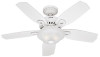
... FULL ASSEMBLY INSTRUCTIONS. Parts List Model # Asm. Dwg. # 28699 G0988-01 28697 G0988-02 28698 G0988-03 Finish Brushed Nickel Antique Pewter New Bronze 28706 G0988-04 White 28707 G0988-05 Black Item Name * Hanging System Kit Ceiling Plate Qnty 1 96759-09 96759-14 96759-30 96759-03 Part # 96759-06 Canopy Canopy Trim Ring Hanger Ball / Downrod Assembly Setscrew Low Profile Washer Canopy Screw Wood Screw 1.5" Wood Screw 3" Flat Washer Mounting Isolator Screw, Low Profile Switch Housing Assembly 1 G1084-09 G1084-14 G1084-30 G1084-03 G1084-06 Blade Set...
... FULL ASSEMBLY INSTRUCTIONS. Parts List Model # Asm. Dwg. # 28699 G0988-01 28697 G0988-02 28698 G0988-03 Finish Brushed Nickel Antique Pewter New Bronze 28706 G0988-04 White 28707 G0988-05 Black Item Name * Hanging System Kit Ceiling Plate Qnty 1 96759-09 96759-14 96759-30 96759-03 Part # 96759-06 Canopy Canopy Trim Ring Hanger Ball / Downrod Assembly Setscrew Low Profile Washer Canopy Screw Wood Screw 1.5" Wood Screw 3" Flat Washer Mounting Isolator Screw, Low Profile Switch Housing Assembly 1 G1084-09 G1084-14 G1084-30 G1084-03 G1084-06 Blade Set...


