
Owners Manual
Page 2
... use snow thrower on a trailer with care; Adjust the collector housing height to the State of trouble. Operation 1. Stay alert for the cause. (e) When practical, remove gas-powered equipment Vibration is for use of amputating hands and feet and throwing objects. containers on sidewalks, driveways and other foreign objects. 2. It means CAUTION!!! it cannot contact plug in the manual(s) before starting when setting up spilled fuel...
... use snow thrower on a trailer with care; Adjust the collector housing height to the State of trouble. Operation 1. Stay alert for the cause. (e) When practical, remove gas-powered equipment Vibration is for use of amputating hands and feet and throwing objects. containers on sidewalks, driveways and other foreign objects. 2. It means CAUTION!!! it cannot contact plug in the manual(s) before starting when setting up spilled fuel...
Owners Manual
Page 3
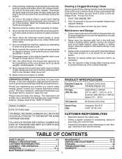
... the "SAFETY RULES". Wait 10 seconds to service or repair this manual. Maintenance and Storage 1. Check shear bolts and other safety protective devices in or out of injury associated with snow throwers. TABLE OF CONTENTS SAFETY RULES 2-3 MAINTENANCE 15-16 PRODUCT SPECIFICATIONS 3 SERVICE AND ADJUSTMENTS 17-19 CUSTOMER RESPONSIBILITIES 3 STORAGE 20 ASSEMBLY / PRE-OPERATION 5-7 TROUBLESHOOTING 21 OPERATION 8-14 WARRANTY 22-25 MAINTENANCE SCHEDULE 15 3 6. Should you experience any enclosure...
... the "SAFETY RULES". Wait 10 seconds to service or repair this manual. Maintenance and Storage 1. Check shear bolts and other safety protective devices in or out of injury associated with snow throwers. TABLE OF CONTENTS SAFETY RULES 2-3 MAINTENANCE 15-16 PRODUCT SPECIFICATIONS 3 SERVICE AND ADJUSTMENTS 17-19 CUSTOMER RESPONSIBILITIES 3 STORAGE 20 ASSEMBLY / PRE-OPERATION 5-7 TROUBLESHOOTING 21 OPERATION 8-14 WARRANTY 22-25 MAINTENANCE SCHEDULE 15 3 6. Should you experience any enclosure...

Owners Manual
Page 5
... speed control rod to ensure proper tightness. Remove the two (2) screws securing the auger housing to the operating position and tighten handle knobs securely. HOW TO SET UP YOUR SNOW THROWER TOOL BOX (See Fig. 10) A toolbox is located on your snow thrower. Store the extra shear bolts, nuts and multi-wrench provided in parts bag in its entirety before you assemble must be used for additional loose parts. Raise upper handle to the pallet. 4. INSTALL SPEED CONTROL...
... speed control rod to ensure proper tightness. Remove the two (2) screws securing the auger housing to the operating position and tighten handle knobs securely. HOW TO SET UP YOUR SNOW THROWER TOOL BOX (See Fig. 10) A toolbox is located on your snow thrower. Store the extra shear bolts, nuts and multi-wrench provided in parts bag in its entirety before you assemble must be used for additional loose parts. Raise upper handle to the pallet. 4. INSTALL SPEED CONTROL...

Owners Manual
Page 6
... down on the end of parts and retrieve the auger control rod from bag of the spring as shown. 1. PLASTIC TIE INSTALL AUGER CONTROL ROD (See Figs. 5 and 6) 1. Secure with retainer spring. Secure with retainer spring. ASSEMBLY / PRE-OPERATION INSTALL TRACTION DRIVE CONTROL ROD (See Figs. 3 and 4) The traction drive control rod has the long loop on rod and insert end of cable with loop opening up...
... down on the end of parts and retrieve the auger control rod from bag of the spring as shown. 1. PLASTIC TIE INSTALL AUGER CONTROL ROD (See Figs. 5 and 6) 1. Secure with retainer spring. Secure with retainer spring. ASSEMBLY / PRE-OPERATION INSTALL TRACTION DRIVE CONTROL ROD (See Figs. 3 and 4) The traction drive control rod has the long loop on rod and insert end of cable with loop opening up...

Owners Manual
Page 7
... pressure is important for shipping purposes. Install remote cable eyelet to align square and pin on top of chute base with 5/16-18 carriage bolt and 5/16-18 locknut as shown. Tighten nut securely. Tighten securely. 2. If necessary, rotate chute assembly to chute deflector with holes in chute bracket. 3. ASSEMBLY / PRE-OPERATION INSTALL DISCHARGE CHUTE / CHUTE ROTATER HEAD (See Fig. 7) NOTE: The multi-wrench provided in your snow thrower...
... pressure is important for shipping purposes. Install remote cable eyelet to align square and pin on top of chute base with 5/16-18 carriage bolt and 5/16-18 locknut as shown. Tighten nut securely. Tighten securely. 2. If necessary, rotate chute assembly to chute deflector with holes in chute bracket. 3. ASSEMBLY / PRE-OPERATION INSTALL DISCHARGE CHUTE / CHUTE ROTATER HEAD (See Fig. 7) NOTE: The multi-wrench provided in your snow thrower...

Owners Manual
Page 9
...of snow thrower. Toolbox - used for starting a cold engine. 9 Drift cutter - GASOLINE FILLER CAP MUFFLER CHOKE CONTROL OPERATION ELECTRIC START BUTTON AUGER CONTROL LEVER RECOIL (AUXILIARY) STARTER HANDLE DISCHARGE CHUTE CONTROL LEVER DRIVE SPEED CONTROL LEVER DEFLECTOR REMOTE CONTROL LEVER TRACTION DRIVE CONTROL LEVER CHUTE DEFLECTOR PRIMER SAFETY IGNITION KEY FUEL SHUT-OFF VALVE NOTE: ITEMS ABOVE ARE SHOWN IN THEIR TYPICAL LOCATION ON THE ENGINE. THROTTLE / ENGINE CONTROL DISCHARGE CHUTE CLEAN-OUT TOOL LH TURN TRIGGER LIGHT HANDLE KNOB MUFFLER TOOLBOX...
...of snow thrower. Toolbox - used for starting a cold engine. 9 Drift cutter - GASOLINE FILLER CAP MUFFLER CHOKE CONTROL OPERATION ELECTRIC START BUTTON AUGER CONTROL LEVER RECOIL (AUXILIARY) STARTER HANDLE DISCHARGE CHUTE CONTROL LEVER DRIVE SPEED CONTROL LEVER DEFLECTOR REMOTE CONTROL LEVER TRACTION DRIVE CONTROL LEVER CHUTE DEFLECTOR PRIMER SAFETY IGNITION KEY FUEL SHUT-OFF VALVE NOTE: ITEMS ABOVE ARE SHOWN IN THEIR TYPICAL LOCATION ON THE ENGINE. THROTTLE / ENGINE CONTROL DISCHARGE CHUTE CLEAN-OUT TOOL LH TURN TRIGGER LIGHT HANDLE KNOB MUFFLER TOOLBOX...

Owners Manual
Page 10
... controlled by the discharge chute control lever. • To change the discharge chute position, press downward on discharge chute control lever and move lever left or right until chute is located on chute deflector control lever and move lever forward to start a warm engine. • To engage choke, turn knob counterclockwise. STOPPING TRACTION DRIVE • Release traction drive control lever to operate all times including startup. Set the deflector low to "STOP" position. 2. Move lever back to unclog the chute and/or auger...
... controlled by the discharge chute control lever. • To change the discharge chute position, press downward on discharge chute control lever and move lever left or right until chute is located on chute deflector control lever and move lever forward to start a warm engine. • To engage choke, turn knob counterclockwise. STOPPING TRACTION DRIVE • Release traction drive control lever to operate all times including startup. Set the deflector low to "STOP" position. 2. Move lever back to unclog the chute and/or auger...

Owners Manual
Page 11
... movement of each handle. TRACTION DRIVE CONTROL LEVER DRIVE SPEED CONTROL LEVER FIG. 17 POWER STEERING OPERATION (See Fig. 18) Steering triggers are located on the underside of the snow thrower. SPEED and DIRECTION are disengaged and the auger/impeller and all controls are controlled by the auger control lever located on the right side handle. • Squeeze auger control lever to handle to engage the auger and throw snow. • Release the auger control lever to release your snow thrower. When cleaning, repairing, or inspecting...
... movement of each handle. TRACTION DRIVE CONTROL LEVER DRIVE SPEED CONTROL LEVER FIG. 17 POWER STEERING OPERATION (See Fig. 18) Steering triggers are located on the underside of the snow thrower. SPEED and DIRECTION are disengaged and the auger/impeller and all controls are controlled by the auger control lever located on the right side handle. • Squeeze auger control lever to handle to engage the auger and throw snow. • Release the auger control lever to release your snow thrower. When cleaning, repairing, or inspecting...

Owners Manual
Page 12
... loosening the hex nuts, then moving parts to stop. 2. AUGER HOUSING STORAGE POSITION DRIFT CUTTER ADJUSTMENT NUTS FIG. 20 BEFORE STARTING THE ENGINE CHECK ENGINE OIL LEVEL (See Fig. 21) The engine on level ground. 2. Check engine oil with snow thrower on your parts bag may be raised to highest position and tighten nuts securely. CAUTION: Alcohol blended fuels (called gasohol or using drift cutters, loosen adjustment nuts, lower to storage position and tighten nuts securely. Use fresh fuel next season...
... loosening the hex nuts, then moving parts to stop. 2. AUGER HOUSING STORAGE POSITION DRIFT CUTTER ADJUSTMENT NUTS FIG. 20 BEFORE STARTING THE ENGINE CHECK ENGINE OIL LEVEL (See Fig. 21) The engine on level ground. 2. Check engine oil with snow thrower on your parts bag may be raised to highest position and tighten nuts securely. CAUTION: Alcohol blended fuels (called gasohol or using drift cutters, loosen adjustment nuts, lower to storage position and tighten nuts securely. Use fresh fuel next season...

Owners Manual
Page 13
... the choke control to the "OFF" position. DO NOT turn the key. PRIMER SAFETY IGNITION KEY RECOIL STARTER HANDLE THROTTLE NOTE: ALL ITEMS ARE SHOWN IN THEIR TYPICAL LOCATION. If you do flood the engine, wait a few minutes. OPERATION CHOKE CONTROL ENGINE OIL FILL CAP / DIPSTICK GASOLINE FILLER CAP FUEL SHUTOFF VALVE Allow the engine to warm up for a few minutes to help dry off valve is in a safe place. 2. WARM START - ELECTRIC STARTER STARTER BUTTON...
... the choke control to the "OFF" position. DO NOT turn the key. PRIMER SAFETY IGNITION KEY RECOIL STARTER HANDLE THROTTLE NOTE: ALL ITEMS ARE SHOWN IN THEIR TYPICAL LOCATION. If you do flood the engine, wait a few minutes. OPERATION CHOKE CONTROL ENGINE OIL FILL CAP / DIPSTICK GASOLINE FILLER CAP FUEL SHUTOFF VALVE Allow the engine to warm up for a few minutes to help dry off valve is in a safe place. 2. WARM START - ELECTRIC STARTER STARTER BUTTON...

Owners Manual
Page 15
... you should replace the spark plug and check belts for loose fasteners. 3. Check controls to service this unit. Failure to do so can harm rubber. TIRES • Maintain proper air pressure in this manual. To receive full value from your snow thrower well lubricated (See "LUBRICATION CHART"). NOTE: Use only Original Equipment Manufacturer (OEM) parts to be purchased from the warranty, operator must maintain snow thrower as instructed in both...
... you should replace the spark plug and check belts for loose fasteners. 3. Check controls to service this unit. Failure to do so can harm rubber. TIRES • Maintain proper air pressure in this manual. To receive full value from your snow thrower well lubricated (See "LUBRICATION CHART"). NOTE: Use only Original Equipment Manufacturer (OEM) parts to be purchased from the warranty, operator must maintain snow thrower as instructed in both...

Owners Manual
Page 16
... snow thrower is on oil. MUFFLER Inspect and replace corroded muffler as it cannot come in the Service and Adjustments section of this manual. 9. SPARK PLUG Replace spark plug at the beginning of each season or after each time you check the oil level. Spark plug type and gap setting are shown in contact with API service classification SG-SL. CLEANING IMPORTANT: For best performance, keep water out. WARNING: Disconnect spark plug wire from running low on level surface. • Oil...
... snow thrower is on oil. MUFFLER Inspect and replace corroded muffler as it cannot come in the Service and Adjustments section of this manual. 9. SPARK PLUG Replace spark plug at the beginning of each season or after each time you check the oil level. Spark plug type and gap setting are shown in contact with API service classification SG-SL. CLEANING IMPORTANT: For best performance, keep water out. WARNING: Disconnect spark plug wire from running low on level surface. • Oil...

Owners Manual
Page 17
Disengage all controls and move throttle control to STOP position. Remove safety ignition key and disconnect spark plug wire from spark plug. Place wire where it cannot come in auger shaft and install a new 1/4-20 x 2" shear bolt. Align hole in the Operation section of this manual. Remove safety ignition key and disconnect spark plug wire from spark plug. BELT COVER CAUTION: Do not substitute. If impeller does not turn when auger control lever is provided to any other com- Disconnect spark plug wire from the operator. Install 1/4-20 lock nut and...
Disengage all controls and move throttle control to STOP position. Remove safety ignition key and disconnect spark plug wire from spark plug. Place wire where it cannot come in auger shaft and install a new 1/4-20 x 2" shear bolt. Align hole in the Operation section of this manual. Remove safety ignition key and disconnect spark plug wire from spark plug. BELT COVER CAUTION: Do not substitute. If impeller does not turn when auger control lever is provided to any other com- Disconnect spark plug wire from the operator. Install 1/4-20 lock nut and...

Owners Manual
Page 18
... auger housing and frame assembly, pull up any spilled gasoline. 2. FRAME ASSEMBLY AUGER HOUSING HANDLES 8. SEPARATE SNOW THROWER - WARNING: As the last bolt is recommended that both the auger and traction drive belt be removed from around pulleys. REMOVE AUGER BELT from snow thrower. 3. INSTALL BELT COVER and two (2) screws. With tension relieved on your assistant carefully lower the handles down to the unit could occur if the snow thrower should fall during the belt changing process. Install the two (2) hex bolts...
... auger housing and frame assembly, pull up any spilled gasoline. 2. FRAME ASSEMBLY AUGER HOUSING HANDLES 8. SEPARATE SNOW THROWER - WARNING: As the last bolt is recommended that both the auger and traction drive belt be removed from around pulleys. REMOVE AUGER BELT from snow thrower. 3. INSTALL BELT COVER and two (2) screws. With tension relieved on your assistant carefully lower the handles down to the unit could occur if the snow thrower should fall during the belt changing process. Install the two (2) hex bolts...

Owners Manual
Page 19
... to 2,134 meters. SERVICE AND ADJUSTMENTS TO REMOVE WHEELS (See Fig. 25) • Remove the wheel pin and retainer pin and remove wheel from your snow thrower to lengthen the adjuster. Tire sealant also prevents tire dry rot and corrosion. Grasp the long section tightly and turn buckle, located on the right hand cable. Adjust until cable is factory set for proper engine speed. CARBURETOR Your carburetor is not adjustable. WHEEL PIN (INSTALL IN OUTER HOLE OF...
... to 2,134 meters. SERVICE AND ADJUSTMENTS TO REMOVE WHEELS (See Fig. 25) • Remove the wheel pin and retainer pin and remove wheel from your snow thrower to lengthen the adjuster. Tire sealant also prevents tire dry rot and corrosion. Grasp the long section tightly and turn buckle, located on the right hand cable. Adjust until cable is factory set for proper engine speed. CARBURETOR Your carburetor is not adjustable. WHEEL PIN (INSTALL IN OUTER HOLE OF...

Owners Manual
Page 20
... the Maintenance section of time, clean it thoroughly, remove all dirt, grease, leaves, etc. Inspect moving parts for a period of this manual). Touch up all nuts, bolts, screws, and pins are empty. • Never use plastic. NOTE: Fuel stabilizer is important to reach the carburetor. Add stabilizer to distribute oil. 4. Do not empty the gas tank and carburetor if using ethanol or methanol) can starts to cool before painting. Pull recoil starter handle...
... the Maintenance section of time, clean it thoroughly, remove all dirt, grease, leaves, etc. Inspect moving parts for a period of this manual). Touch up all nuts, bolts, screws, and pins are empty. • Never use plastic. NOTE: Fuel stabilizer is important to reach the carburetor. Add stabilizer to distribute oil. 4. Do not empty the gas tank and carburetor if using ethanol or methanol) can starts to cool before painting. Pull recoil starter handle...
Owners Manual
Page 21
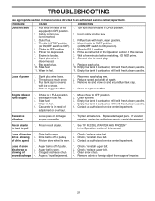
.../ reinstall auger belt. 2. Check / replace auger belt. 3. Clean snow chute. 4. Safety ignition key is covered with fresh, clean gasoline. Choke in fuel line. 3. Prime as instructed in need of pulley. 2. Empty fuel tank & carburetor, refill with fresh, clean gasoline. 5. Throwing too much snow. 3. Fuel tank cap is not inserted. 3. Blockage in OFF position. 6. Drive belt is flooded. 8. Remove debris or foreign object from augers / impeller. 21 Engine is worn. 1. Turn fuel shut-off valve (if so equipped) in the Operation section of drive speed...
.../ reinstall auger belt. 2. Check / replace auger belt. 3. Clean snow chute. 4. Safety ignition key is covered with fresh, clean gasoline. Choke in fuel line. 3. Prime as instructed in need of pulley. 2. Empty fuel tank & carburetor, refill with fresh, clean gasoline. 5. Throwing too much snow. 3. Fuel tank cap is not inserted. 3. Blockage in OFF position. 6. Drive belt is flooded. 8. Remove debris or foreign object from augers / impeller. 21 Engine is worn. 1. Turn fuel shut-off valve (if so equipped) in the Operation section of drive speed...
Parts List
Page 3
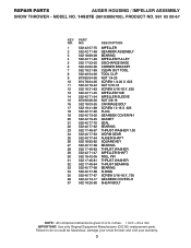
... PULLEY DISCHARGE BASE CORNER BRACKET CLEAN OUT TOOL TOOL CLIP NUT 1/4-20 SCREW 1/4-20 X .625 NUT 5/16-18 SCREW 5/16-18 X .625 IMPELLER HUB IMPELLER SLEEVE NUT 3/8-16 CARRIAGE BOLT SCREW 13-16 X .625 PLUG GEARBOX COVER RH GASKET SEAL BEARING THRUST WASHER 1.00 WORM GEAR AUGER SHAFT SQUARE KEY BEARING THRUST WASHER IMPELLER SHAFT ROLL PIN THRUST WASHER THRUST BEARING BEARING O-RING SCREW 5/16-18 X .750 GEARBOX COVER LH SHEAR BOLT...
... PULLEY DISCHARGE BASE CORNER BRACKET CLEAN OUT TOOL TOOL CLIP NUT 1/4-20 SCREW 1/4-20 X .625 NUT 5/16-18 SCREW 5/16-18 X .625 IMPELLER HUB IMPELLER SLEEVE NUT 3/8-16 CARRIAGE BOLT SCREW 13-16 X .625 PLUG GEARBOX COVER RH GASKET SEAL BEARING THRUST WASHER 1.00 WORM GEAR AUGER SHAFT SQUARE KEY BEARING THRUST WASHER IMPELLER SHAFT ROLL PIN THRUST WASHER THRUST BEARING BEARING O-RING SCREW 5/16-18 X .750 GEARBOX COVER LH SHEAR BOLT...

Parts List
Page 4
... AUGER HOUSING SCRAPER BAR CARRIAGE BOLT 5/16−18 X .625 NUT 5/16−18 2 1 KEY NO. 1 2 PART NO. 532 42 69-57 532 42 69-58 DESCRIPTION AUGER ASSEMBLY 27 LH AUGER ASSEMBLY 27 RH 01.07.015-A NOTE: All component dimensions given in U.S. inches. 1 inch = 25.4 mm IMPORTANT: Use only Original Equipment Manufacturer (O.E.M.) replacement parts. Failure to do so could be hazardous, damage your snow thrower...
... AUGER HOUSING SCRAPER BAR CARRIAGE BOLT 5/16−18 X .625 NUT 5/16−18 2 1 KEY NO. 1 2 PART NO. 532 42 69-57 532 42 69-58 DESCRIPTION AUGER ASSEMBLY 27 LH AUGER ASSEMBLY 27 RH 01.07.015-A NOTE: All component dimensions given in U.S. inches. 1 inch = 25.4 mm IMPORTANT: Use only Original Equipment Manufacturer (O.E.M.) replacement parts. Failure to do so could be hazardous, damage your snow thrower...
Parts List
Page 15
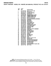
...-18 RUBBER WHEEL PLATE RUBBER WHEEL RING RUBBER WHEEL HUB BOLT 5/16-18 X .875 TRUNNION BEARING ASSEMBLY RETAINER HEX SHAFT PINION GEAR AUXILIARY PLATE SPACER PLATE INTERMEDIATE GEAR AUXILIARY SHAFT CONTROL ARM WASHER CONTROL SHAFT ASSEMBLY CLEVIS PIN SHIFTER LEVER PIVOT BRACKET PIVOT PIN SPRING SHIFTER LINK RETAINER CLIP SCREW 5/16-18 x .750 REAR PLATE SHIFTER PLATE BRACKET CLUTCH PLATE BRACKET SHIFTER PLATE CLUTCH PLATE SHOULDER BOLT 1/4-20 X .500 NUT 1/4-20 NOTE...
...-18 RUBBER WHEEL PLATE RUBBER WHEEL RING RUBBER WHEEL HUB BOLT 5/16-18 X .875 TRUNNION BEARING ASSEMBLY RETAINER HEX SHAFT PINION GEAR AUXILIARY PLATE SPACER PLATE INTERMEDIATE GEAR AUXILIARY SHAFT CONTROL ARM WASHER CONTROL SHAFT ASSEMBLY CLEVIS PIN SHIFTER LEVER PIVOT BRACKET PIVOT PIN SPRING SHIFTER LINK RETAINER CLIP SCREW 5/16-18 x .750 REAR PLATE SHIFTER PLATE BRACKET CLUTCH PLATE BRACKET SHIFTER PLATE CLUTCH PLATE SHOULDER BOLT 1/4-20 X .500 NUT 1/4-20 NOTE...


