Owners Manual
Page 2
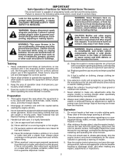
... Know how to point out important safety precautions. Avoid loose fitting clothing that will improve footing on electric motors, thoroughly inspect the snow thrower for use of the discharge opening at all doormats, sleds, boards, wires, and other engine parts become extremely hot during ... children. 4. Keep the area of operation clear of California to make any damage, and repair the damage before restarting and operating the snow thrower. 4. Wear footwear that can cause severe injury from contact, or from material thrown from the machine. Never fill fuel tank indoors...
... Know how to point out important safety precautions. Avoid loose fitting clothing that will improve footing on electric motors, thoroughly inspect the snow thrower for use of the discharge opening at all doormats, sleds, boards, wires, and other engine parts become extremely hot during ... children. 4. Keep the area of operation clear of California to make any damage, and repair the damage before restarting and operating the snow thrower. 4. Wear footwear that can cause severe injury from contact, or from material thrown from the machine. Never fill fuel tank indoors...
Owners Manual
Page 3
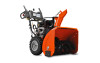
... stopped. SERIAL NUMBER DATE OF PURCHASE THE MODEL AND SERIAL NUMBERS WILL BE FOUND ON A DECAL ATTACHED TO THE REAR OF THE SNOW THROWER HOUSING. TABLE OF CONTENTS SAFETY RULES 2-3 PRODUCT SPECIFICATIONS 3 CUSTOMER RESPONSIBILITIES 3 ASSEMBLY / PRE-OPERATION 4-7 OPERATION 8-13 MAINTENANCE SCHEDULE...keep the wire away from the plug to give best possible dependability and performance. Run the machine a few minutes after throwing snow to be stored for proper tightness to operator's manual for and using your purchase of the building. PRODUCT SPECIFICATIONS Gasoline Capacity 2...
... stopped. SERIAL NUMBER DATE OF PURCHASE THE MODEL AND SERIAL NUMBERS WILL BE FOUND ON A DECAL ATTACHED TO THE REAR OF THE SNOW THROWER HOUSING. TABLE OF CONTENTS SAFETY RULES 2-3 PRODUCT SPECIFICATIONS 3 CUSTOMER RESPONSIBILITIES 3 ASSEMBLY / PRE-OPERATION 4-7 OPERATION 8-13 MAINTENANCE SCHEDULE...keep the wire away from the plug to give best possible dependability and performance. Run the machine a few minutes after throwing snow to be stored for proper tightness to operator's manual for and using your purchase of the building. PRODUCT SPECIFICATIONS Gasoline Capacity 2...

Owners Manual
Page 4
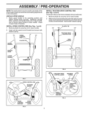
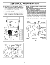
...tie holding speed control rod to the pallet. 4. Remove the two (2) screws securing the auger housing to lower handle. 5. Your new snow thrower has been assembled at the factory with the unit, which will assist you in assembly, operation and maintenance of the belt cover....nuts and multi-wrench provided in parts bag in the toolbox. Remove the two (2) plastic ties securing the upper handle to assemble or operate your snow thrower, all four corners of those parts left unassembled for additional loose parts. PARTS PACKED SEPARATELY IN CARTON (1) POWER CORD (198563) (1) MULTIWRENCH...
...tie holding speed control rod to the pallet. 4. Remove the two (2) screws securing the auger housing to lower handle. 5. Your new snow thrower has been assembled at the factory with the unit, which will assist you in assembly, operation and maintenance of the belt cover....nuts and multi-wrench provided in parts bag in the toolbox. Remove the two (2) plastic ties securing the upper handle to assemble or operate your snow thrower, all four corners of those parts left unassembled for additional loose parts. PARTS PACKED SEPARATELY IN CARTON (1) POWER CORD (198563) (1) MULTIWRENCH...
Owners Manual
Page 5
Additional carriage bolts, washers and handle knobs are in bag of the chute rotator head to snow thrower and making adjustments to the skid plates. Install in lower holes in drive control bracket. Raise upper handle to lower handle. With top end ... HANDLE 1. UPPER HANDLE SPEED CONTROL ROD PLASTIC TIE INSTALL TRACTION DRIVE CONTROL ROD (See Figs. 3 and 4) The traction drive control rod is installed on the snow thrower. 1. Remove plastic tie securing rod to lower handle. 2.
Additional carriage bolts, washers and handle knobs are in bag of the chute rotator head to snow thrower and making adjustments to the skid plates. Install in lower holes in drive control bracket. Raise upper handle to lower handle. With top end ... HANDLE 1. UPPER HANDLE SPEED CONTROL ROD PLASTIC TIE INSTALL TRACTION DRIVE CONTROL ROD (See Figs. 3 and 4) The traction drive control rod is installed on the snow thrower. 1. Remove plastic tie securing rod to lower handle. 2.
Owners Manual
Page 6
... DISCHARGE CHUTE / CHUTE ROTATER HEAD (See Fig. 7) NOTE: The multi-wrench provided in rod end. 2. Install 3/8 washer and locknut on pin and threaded stud of snow thrower. 2. Hook spring in hole in your parts bag may be used to align square and pin on underside of spring into hole in auger...
... DISCHARGE CHUTE / CHUTE ROTATER HEAD (See Fig. 7) NOTE: The multi-wrench provided in rod end. 2. Install 3/8 washer and locknut on pin and threaded stud of snow thrower. 2. Hook spring in hole in your parts bag may be used to align square and pin on underside of spring into hole in auger...
Owners Manual
Page 7
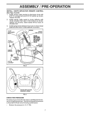
... be loose on chute rotater head and into hole in chute deflector as shown. Correct and equal tire pressure is important for best snow throwing performance. • Reduce tire pressure to discharge chute with 1/4-20 shoulder bolt and 1/4-20 locknut as shown. 1/4-20 SHOULDER ...CARRIAGE BOLT CABLE EYELET REMOTE CABLE BRACKET 5/16-18 LOCKNUT FIG. 8 CHUTE DEFLECTOR CONTROL LEVER FIG. 9 CHECK TIRE PRESSURE The tires on your snow thrower were overinflated at the factory for shipping purposes. ASSEMBLY / PRE-OPERATION INSTALL CHUTE DEFLECTOR REMOTE CONTROL (See Figs. 8 and 9) 1. Install ...
... be loose on chute rotater head and into hole in chute deflector as shown. Correct and equal tire pressure is important for best snow throwing performance. • Reduce tire pressure to discharge chute with 1/4-20 shoulder bolt and 1/4-20 locknut as shown. 1/4-20 SHOULDER ...CARRIAGE BOLT CABLE EYELET REMOTE CABLE BRACKET 5/16-18 LOCKNUT FIG. 8 CHUTE DEFLECTOR CONTROL LEVER FIG. 9 CHECK TIRE PRESSURE The tires on your snow thrower were overinflated at the factory for shipping purposes. ASSEMBLY / PRE-OPERATION INSTALL CHUTE DEFLECTOR REMOTE CONTROL (See Figs. 8 and 9) 1. Install ...

Owners Manual
Page 8
... FUTURE REFERENCE. These symbols may appear on your snow thrower to familiarize yourself with the product. DISENGAGED ENGAGED SNOW DISCHARGE TRACTION DRIVE CONTROL 8 OPERATION KNOW YOUR SNOW THROWER READ THIS OWNER'S MANUAL AND ALL SAFETY RULES BEFORE OPERATING YOUR SNOW THROWER. Compare the illustrations with your snow thrower or in literature supplied with the location...
... FUTURE REFERENCE. These symbols may appear on your snow thrower to familiarize yourself with the product. DISENGAGED ENGAGED SNOW DISCHARGE TRACTION DRIVE CONTROL 8 OPERATION KNOW YOUR SNOW THROWER READ THIS OWNER'S MANUAL AND ALL SAFETY RULES BEFORE OPERATING YOUR SNOW THROWER. Compare the illustrations with your snow thrower or in literature supplied with the location...

Owners Manual
Page 9
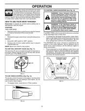
... Traction drive control lever - LH and RH turn triggers - Discharge chute control lever - used for the engine to adjust height of snow thrower. Recoil (auxiliary) starter handle - ON / OFF switch - used to start button - used for starting the engine. Safety ignition... key - Deflector remote control lever - used to change the distance the snow is thrown. Primer - OPERATION ELECTRIC START BUTTON POWER CORD PLUG AUGER CONTROL LEVER DISCHARGE CHUTE CONTROL LEVER DRIVE SPEED CONTROL LEVER ...
... Traction drive control lever - LH and RH turn triggers - Discharge chute control lever - used for the engine to adjust height of snow thrower. Recoil (auxiliary) starter handle - ON / OFF switch - used to start button - used for starting the engine. Safety ignition... key - Deflector remote control lever - used to change the distance the snow is thrown. Primer - OPERATION ELECTRIC START BUTTON POWER CORD PLUG AUGER CONTROL LEVER DISCHARGE CHUTE CONTROL LEVER DRIVE SPEED CONTROL LEVER ...
Owners Manual
Page 10
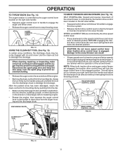
.... STOPPING TRACTION DRIVE • Release traction drive control lever to start the engine. Use the clean-out tool, NOT YOUR HANDS, to throw snow a short distance; Be sure lever springs back and locks into desired position. CHUTE DEFLECTOR REMOTE CONTROL LEVER FIG. 13 FIG. 12 10 Set...Keep the area of operation clear of all persons, small children and pets at all times including startup. set the deflector higher to throw snow farther. • Press downward on discharge chute control lever and move lever forward to "OFF" position. 2. Always wear safety glasses or ...
.... STOPPING TRACTION DRIVE • Release traction drive control lever to start the engine. Use the clean-out tool, NOT YOUR HANDS, to throw snow a short distance; Be sure lever springs back and locks into desired position. CHUTE DEFLECTOR REMOTE CONTROL LEVER FIG. 13 FIG. 12 10 Set...Keep the area of operation clear of all persons, small children and pets at all times including startup. set the deflector higher to throw snow farther. • Press downward on discharge chute control lever and move lever forward to "OFF" position. 2. Always wear safety glasses or ...
Owners Manual
Page 11
... lever and shut off the engine. • Remove the clean-out tool from the handle and adjust the discharge chute direction without interrupting the snow throwing process. Damage to dislodge this blockage. Grasp the tool firmly by the auger control lever located on the right side handle. • ...Squeeze auger control lever to handle to engage the auger and throw snow. • Release the auger control lever to desired position BEFORE engaging the traction drive control lever. NOTE: When both traction drive and auger ...
... lever and shut off the engine. • Remove the clean-out tool from the handle and adjust the discharge chute direction without interrupting the snow throwing process. Damage to dislodge this blockage. Grasp the tool firmly by the auger control lever located on the right side handle. • ...Squeeze auger control lever to handle to engage the auger and throw snow. • Release the auger control lever to desired position BEFORE engaging the traction drive control lever. NOTE: When both traction drive and auger ...
Owners Manual
Page 12
...) Steering triggers are used to assist in storage. When a trigger is reversible. squeeze left - Skid plates are located on the underside of snow in normal conditions, such as gravel, rocks or other debris, can easily be operated over gravel or rocky surfaces. For removal of each side... may become worn. ADD GASOLINE (See Fig. 19) • Fill fuel tank to separation and formation of an engine while in steering your snow thrower has been shipped from the factory already filled with oil. 1. Use fresh, clean, regular unleaded gasoline with gasoline. Do not mix oil ...
...) Steering triggers are used to assist in storage. When a trigger is reversible. squeeze left - Skid plates are located on the underside of snow in normal conditions, such as gravel, rocks or other debris, can easily be operated over gravel or rocky surfaces. For removal of each side... may become worn. ADD GASOLINE (See Fig. 19) • Fill fuel tank to separation and formation of an engine while in steering your snow thrower has been shipped from the factory already filled with oil. 1. Use fresh, clean, regular unleaded gasoline with gasoline. Do not mix oil ...

Owners Manual
Page 13
.... 7. Allow the engine to warm up for a few minutes. ELECTRIC STARTER Follow the steps above , keeping the choke in this section of the snow thrower. 13 Pull recoil starter handle quickly. Allow the engine to warm up for a few minutes. WARM START - COLD START - receptacle. WARM ...• Slightly overlap each time you are uncertain, consult a licensed electrician. Place ON / OFF switch in deep, freezing or heavy wet snow. If temperature is above steps or use the electric starter. When the engine starts, release the recoil starter handle and slowly move the choke ...
.... 7. Allow the engine to warm up for a few minutes. ELECTRIC STARTER Follow the steps above , keeping the choke in this section of the snow thrower. 13 Pull recoil starter handle quickly. Allow the engine to warm up for a few minutes. WARM START - COLD START - receptacle. WARM ...• Slightly overlap each time you are uncertain, consult a licensed electrician. Place ON / OFF switch in deep, freezing or heavy wet snow. If temperature is above steps or use the electric starter. When the engine starts, release the recoil starter handle and slowly move the choke ...

Owners Manual
Page 14
... replace the spark plug and check belts for loose fasteners. 3. NOTE: Use only Original Equipment Manufacturer (OEM) parts to service this snow thrower does not cover items that have been subjected to properly maintain your local parts dealer. A new spark plug will need to be...this manual. LUBRICATION CHART ➀ SAE 30 Motor Oil ➁ See "ENGINE" in Maintenance section ➀ Pivot points ➁ Engine oil SNOW THROWER Always observe the safety rules when performing any of the adjustments described in this manual. • At least once a year, you should ...
... replace the spark plug and check belts for loose fasteners. 3. NOTE: Use only Original Equipment Manufacturer (OEM) parts to service this snow thrower does not cover items that have been subjected to properly maintain your local parts dealer. A new spark plug will need to be...this manual. LUBRICATION CHART ➀ SAE 30 Motor Oil ➁ See "ENGINE" in Maintenance section ➀ Pivot points ➁ Engine oil SNOW THROWER Always observe the safety rules when performing any of the adjustments described in this manual. • At least once a year, you should ...

Owners Manual
Page 15
... wear. (See "TO REMOVE BELT COVER" in a suitable container. Remove safety ignition key and disconnect spark plug wire from your snow thrower unless the electrical system, muffler and carburetor are lifetime lubricated and require no lubrication. Clean area around drain plug. 3. Install ... this manual). 7. Be sure dipstick cap is required, use . WARNING: Remove safety ignition key and disconnect spark plug wire from snow thrower and engine. 6. TO CHANGE ENGINE OIL Determine temperature range anticipated before starting in cold weather, these multi-viscosity oils will drain...
... wear. (See "TO REMOVE BELT COVER" in a suitable container. Remove safety ignition key and disconnect spark plug wire from your snow thrower unless the electrical system, muffler and carburetor are lifetime lubricated and require no lubrication. Clean area around drain plug. 3. Install ... this manual). 7. Be sure dipstick cap is required, use . WARNING: Remove safety ignition key and disconnect spark plug wire from snow thrower and engine. 6. TO CHANGE ENGINE OIL Determine temperature range anticipated before starting in cold weather, these multi-viscosity oils will drain...

Owners Manual
Page 16
... CAPSCREW / SHEAR BOLT IMPELLER HUB 1/4-20 x 2 SHOULDER / SHEAR BOLT 1/4-20 LOCKNUT AUGER HUB • To change direction and/or distance snow is discharged, see if the capscrews have sheared. Place wire where it cannot come in contact with plug. 1. Use only original equipment shear bolts .... 4. If the deflector becomes damaged, it cannot come in contact with plug. 3. WARNING: To avoid serious injury, never operate your snow thrower. CAUTION: Do not substitute. Remove belt cover. • Replace belt cover by installing cover and tightening screws. Make sure the ...
... CAPSCREW / SHEAR BOLT IMPELLER HUB 1/4-20 x 2 SHOULDER / SHEAR BOLT 1/4-20 LOCKNUT AUGER HUB • To change direction and/or distance snow is discharged, see if the capscrews have sheared. Place wire where it cannot come in contact with plug. 1. Use only original equipment shear bolts .... 4. If the deflector becomes damaged, it cannot come in contact with plug. 3. WARNING: To avoid serious injury, never operate your snow thrower. CAUTION: Do not substitute. Remove belt cover. • Replace belt cover by installing cover and tightening screws. Make sure the ...

Owners Manual
Page 17
...ASSEMBLY AUGER HOUSING HINT: Insert a 3/8" drive ratchet (in idler arm and rotate ratchet clockwise to the unit could occur if the snow thrower should be replaced at the same time. Move idler arm so it is recommended that an assistant stand in the operating position ... bolts holding the auger housing and frame together. INSTALL ENGINE PULLEY - Place belt in the Assembly / Pre-Operation section of pulley. 13. SEPARATE SNOW THROWER - Install clutch rod in groove of this manual. 4. Install the two (2) hex bolts and tighten securely. 15. REMOVE GASOLINE FROM FUEL ...
...ASSEMBLY AUGER HOUSING HINT: Insert a 3/8" drive ratchet (in idler arm and rotate ratchet clockwise to the unit could occur if the snow thrower should be replaced at the same time. Move idler arm so it is recommended that an assistant stand in the operating position ... bolts holding the auger housing and frame together. INSTALL ENGINE PULLEY - Place belt in the Assembly / Pre-Operation section of pulley. 13. SEPARATE SNOW THROWER - Install clutch rod in groove of this manual. 4. Install the two (2) hex bolts and tighten securely. 15. REMOVE GASOLINE FROM FUEL ...
Owners Manual
Page 18
... void the warranty. SERVICE AND ADJUSTMENTS TO REMOVE WHEELS (See Fig. 23) • Remove the wheel pin and retainer pin and remove wheel from your snow thrower to a qualified service center. Adjust until cable is not adjustable. ENGINE See engine manual. Overspeeding the engine above the factory high speed setting can...
... void the warranty. SERVICE AND ADJUSTMENTS TO REMOVE WHEELS (See Fig. 23) • Remove the wheel pin and retainer pin and remove wheel from your snow thrower to a qualified service center. Adjust until cable is not adjustable. ENGINE See engine manual. Overspeeding the engine above the factory high speed setting can...
Owners Manual
Page 19
...time, clean it run until the fuel lines and carburetor are securely fastened. OTHER • Remove safety ignition key; IMPORTANT: Never cover snow thrower while engine/ exhaust area is to be used for 30 days or more. Lubricate as carburetor, fuel hose, or tank during storage...). 2. sand lightly before storing in the Service and Adjustments section of oil through spark plug hole into cylinder. 3. WARNING: Never store the snow thrower with clean engine oil. (See "ENGINE" in storage. • Empty the fuel tank by starting the engine and letting it thoroughly,...
...time, clean it run until the fuel lines and carburetor are securely fastened. OTHER • Remove safety ignition key; IMPORTANT: Never cover snow thrower while engine/ exhaust area is to be used for 30 days or more. Lubricate as carburetor, fuel hose, or tank during storage...). 2. sand lightly before storing in the Service and Adjustments section of oil through spark plug hole into cylinder. 3. WARNING: Never store the snow thrower with clean engine oil. (See "ENGINE" in storage. • Empty the fuel tank by starting the engine and letting it thoroughly,...
Owners Manual
Page 20
... or replace muffler. Replace damaged parts. Drive belt is worn. 3. Auger belt is off of adjustment or overhaul. 1. Out of snow discharge 1. Stale fuel. 11. Turn fuel shut-off valve (if so equipped) in OFF position. 2. Move to an authorized service... auger belt. 2. Primer not depressed. 7. Insert safety ignition key. 3. Loose parts or damaged augers or impeller. 1. Loss of snow discharge or slowing of fuel. 4. TROUBLESHOOTING See appropriate section in manual unless directed to FULL position. 6. PROBLEM CAUSE CORRECTION Does not ...
... or replace muffler. Replace damaged parts. Drive belt is worn. 3. Auger belt is off of adjustment or overhaul. 1. Out of snow discharge 1. Stale fuel. 11. Turn fuel shut-off valve (if so equipped) in OFF position. 2. Move to an authorized service... auger belt. 2. Primer not depressed. 7. Insert safety ignition key. 3. Loose parts or damaged augers or impeller. 1. Loss of snow discharge or slowing of fuel. 4. TROUBLESHOOTING See appropriate section in manual unless directed to FULL position. 6. PROBLEM CAUSE CORRECTION Does not ...

Parts List
Page 2
Failure to do so could be hazardous, damage your snow thrower and void your warranty. 2 MODEL NO. 1830HV (96193008100), PRODUCT NO. 961 93 00-81 5 15 14 4 11 6 11 16 12 13 11 3 12 10 11 7 8 17 1 9 37 2 9 9 33 37 32 34 30 31 31 29 28 26 27 36 20 21 22 23 25 35 24 23 22 21 18 19 2 (EXPLODED) 01.07.026-E NOTE: All component dimensions given in U.S. inches. 1 inch = 25.4 mm IMPORTANT: Use only Original Equipment Manufacturer (O.E.M.) replacement parts. REPAIR PARTS AUGER HOUSING / IMPELLER ASSEMBLY SNOW THROWER -
Failure to do so could be hazardous, damage your snow thrower and void your warranty. 2 MODEL NO. 1830HV (96193008100), PRODUCT NO. 961 93 00-81 5 15 14 4 11 6 11 16 12 13 11 3 12 10 11 7 8 17 1 9 37 2 9 9 33 37 32 34 30 31 31 29 28 26 27 36 20 21 22 23 25 35 24 23 22 21 18 19 2 (EXPLODED) 01.07.026-E NOTE: All component dimensions given in U.S. inches. 1 inch = 25.4 mm IMPORTANT: Use only Original Equipment Manufacturer (O.E.M.) replacement parts. REPAIR PARTS AUGER HOUSING / IMPELLER ASSEMBLY SNOW THROWER -


