

Owner Manual
Page 2
Operator's manual 2. 4 mm hex 3. Loop handle 4. Start/stop button 7. Speed mode button 8. Battery charger cord 11. Knob 5. Battery charger 3 8 4 9 11 10 12. Battery 15. Power trigger lockout 9. Power and Warning LED 13. Battery release buttons 14. Warning LED 17. Locking pin 21. User interface 6. Battery indicator button 18. Bevel gear 22. Shaft 20. Contents Introduction 2 Safety 4 Assembly 11 Operation 13 Maintenance 16 Troubleshooting 18 Transportation, storage and disposal 18 Technical data 19 Accessories 20 Registered...
Operator's manual 2. 4 mm hex 3. Loop handle 4. Start/stop button 7. Speed mode button 8. Battery charger cord 11. Knob 5. Battery charger 3 8 4 9 11 10 12. Battery 15. Power trigger lockout 9. Power and Warning LED 13. Battery release buttons 14. Warning LED 17. Locking pin 21. User interface 6. Battery indicator button 18. Bevel gear 22. Shaft 20. Contents Introduction 2 Safety 4 Assembly 11 Operation 13 Maintenance 16 Troubleshooting 18 Transportation, storage and disposal 18 Technical data 19 Accessories 20 Registered...

Owner Manual
Page 3
... the serial number. Use heavy-duty slip-resistant boots. This product can fall on you understand the instructions before maintenance. trimmer heads with trimmer cord. TheBluetooth® symbol will be dangerous! The product has protection against splashing water. It is extremely important that our product causes if: • the product is incorrectly repaired. 1938 - 003 - 24.02.2023 3 Manufacturer Husqvarna AB...
... the serial number. Use heavy-duty slip-resistant boots. This product can fall on you understand the instructions before maintenance. trimmer heads with trimmer cord. TheBluetooth® symbol will be dangerous! The product has protection against splashing water. It is extremely important that our product causes if: • the product is incorrectly repaired. 1938 - 003 - 24.02.2023 3 Manufacturer Husqvarna AB...
Owner Manual
Page 4
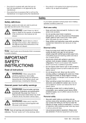
... alert, watch what you to lose control. Note: Save all instructions listed below may ignite the dust or fumes. • Keep children and bystanders away while operating a power tool. Do not use reduces the risk of electric shock. • If operating a power tool in a damp location is a risk of injury or death for future reference. Electrical safety • Power tool plugs must match the outlet. Failure to...
... alert, watch what you to lose control. Note: Save all instructions listed below may ignite the dust or fumes. • Keep children and bystanders away while operating a power tool. Do not use reduces the risk of electric shock. • If operating a power tool in a damp location is a risk of injury or death for future reference. Electrical safety • Power tool plugs must match the outlet. Failure to...
Owner Manual
Page 5
... battery pack. • Use power tools only with specifically designated battery packs. Slippery handles and grasping surfaces do not charge the battery pack or tool outside the specified range may cause explosion. • Follow all times. Liquid ejected from oil and grease. Any power tool that the safety of untrained users. • Maintain power tools and accessories. Check for safe handling and control of parts and any adjustments, changing accessories, or storing power tools. Use of tools...
... battery pack. • Use power tools only with specifically designated battery packs. Slippery handles and grasping surfaces do not charge the battery pack or tool outside the specified range may cause explosion. • Follow all times. Liquid ejected from oil and grease. Any power tool that the safety of untrained users. • Maintain power tools and accessories. Check for safe handling and control of parts and any adjustments, changing accessories, or storing power tools. Use of tools...

Owner Manual
Page 6
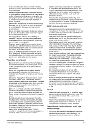
... tightened blade securing nuts or bolts may either damage the blade or result in it becoming detached. • The rated rotational speed of injury. • Follow instructions for changing accessories. Adequate protective equipment will reduce the likelihood of the product before use replacement cutters, lines, cutting heads and blades specified by flying debris or accidental contact with the cutting line or blade. • While operating the machine...
... tightened blade securing nuts or bolts may either damage the blade or result in it becoming detached. • The rated rotational speed of injury. • Follow instructions for changing accessories. Adequate protective equipment will reduce the likelihood of the product before use replacement cutters, lines, cutting heads and blades specified by flying debris or accidental contact with the cutting line or blade. • While operating the machine...
Owner Manual
Page 7
... ensure that the trimmer head and trimmer guard are cracked. Avoid all nuts and screws are the cutting attachments recommended in the vicinity of the product and/or the battery to cover every conceivable situation you are working order. However, do not play with this product are tight. • Check that they have been given supervision or instruction concerning use the machine in...
... ensure that the trimmer head and trimmer guard are cracked. Avoid all nuts and screws are the cutting attachments recommended in the vicinity of the product and/or the battery to cover every conceivable situation you are working order. However, do not play with this product are tight. • Check that they have been given supervision or instruction concerning use the machine in...

Owner Manual
Page 8
... no clothes or parts of strength, changes in a residential installation. Keep the product below waist level. • Watch out for stumps of injury if an accident does occur. Always remove your dealer help . Such symptoms include numbness, loss of feeling, tingling, pricking, pain, loss of the body come in contact with the cutting attachment when the product...
... no clothes or parts of strength, changes in a residential installation. Keep the product below waist level. • Watch out for stumps of injury if an accident does occur. Always remove your dealer help . Such symptoms include numbness, loss of feeling, tingling, pricking, pain, loss of the body come in contact with the cutting attachment when the product...
Owner Manual
Page 9
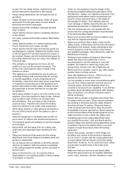
... do a check of the user interface 1. See instructions under the heading Introduction on page 2 to find where these checks, contact your product. If you must also use a product with bare feet. To do a check of the power trigger lockout The power trigger lockout is not carried out correctly and if service and/or repairs are located on your service agent to get it operates correctly. Approved...
... do a check of the user interface 1. See instructions under the heading Introduction on page 2 to find where these checks, contact your product. If you must also use a product with bare feet. To do a check of the power trigger lockout The power trigger lockout is not carried out correctly and if service and/or repairs are located on your service agent to get it operates correctly. Approved...
Owner Manual
Page 10
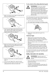
... the trimmer guard is not damaged. • Make sure that the trimmer line is in vibrations that are not necessary. Do not use a cutting attachment without an approved and correctly attached cutting attachment guard. Stop the product and remove the battery. 2. B A 3. Push the power trigger fully to To start the product on the cord. To do a check of the operator. The cutting attachment guard stops objects that the power trigger is locked when the lock is...
... the trimmer guard is not damaged. • Make sure that the trimmer line is in vibrations that are not necessary. Do not use a cutting attachment without an approved and correctly attached cutting attachment guard. Stop the product and remove the battery. 2. B A 3. Push the power trigger fully to To start the product on the cord. To do a check of the operator. The cutting attachment guard stops objects that the power trigger is locked when the lock is...
Owner Manual
Page 11
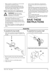
... assemble the two-piece shaft 1. Turn the knob to a comfortable position. 5. Adjust the product to loosen the coupling. 2. Do not place loop handle or suspension ring on the coupling. Attach the nut, the knob and the screw, do the maintenance and servicing shown in this operator's manual. If not all servicing and repair work, especially for the safety devices on the product. • Remove the battery before you do maintenance...
... assemble the two-piece shaft 1. Turn the knob to a comfortable position. 5. Adjust the product to loosen the coupling. 2. Do not place loop handle or suspension ring on the coupling. Attach the nut, the knob and the screw, do the maintenance and servicing shown in this operator's manual. If not all servicing and repair work, especially for the safety devices on the product. • Remove the battery before you do maintenance...
Owner Manual
Page 12
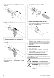
Turn the knob 3 turns or more to use the cutting attachment guard that the motor is recommended for the cutting attachment. Adjust the ring to make the product balanced, and easy to loosen the coupling. 2. WARNING: Use protective gloves. Tighten the knob fully. C To install the harness support hook 1. To disassemble the two-piece shaft 1. WARNING: Always use . Install the harness support hook between the loop handle and the throttle handle. Put on...
Turn the knob 3 turns or more to use the cutting attachment guard that the motor is recommended for the cutting attachment. Adjust the ring to make the product balanced, and easy to loosen the coupling. 2. WARNING: Use protective gloves. Tighten the knob fully. C To install the harness support hook 1. To disassemble the two-piece shaft 1. WARNING: Always use . Install the harness support hook between the loop handle and the throttle handle. Put on...
Owner Manual
Page 13
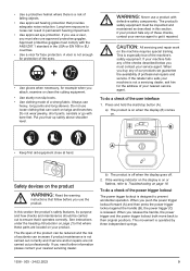
.../support flange engages correctly in the centre hole of the holes in the drive disc with the product. 1. Put the locking pin (C) in the gear housing. 3. Make sure that the raised section on the output shaft. 2. To remove the cutting attachment guard • Loosen the bolt (C) and remove the cutting attachment guard (A) from the shaft. A B C A Introduction Operation To connect the battery to attach. See the chapter on Technical data. Turn the trimmer head...
.../support flange engages correctly in the centre hole of the holes in the drive disc with the product. 1. Put the locking pin (C) in the gear housing. 3. Make sure that the raised section on the output shaft. 2. To remove the cutting attachment guard • Loosen the bolt (C) and remove the cutting attachment guard (A) from the shaft. A B C A Introduction Operation To connect the battery to attach. See the chapter on Technical data. Turn the trimmer head...
Owner Manual
Page 14
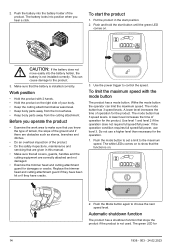
... of operation for damages or cracks. Push the mode button to set a limit to choose the next speed level. 2. Replace the trimmer head and cutting attachment guard if they have been hit or if they have cracks. 3. Use the power trigger to the product. 3. The mode button has 3 speed levels. Put the product in this manual. • Make sure that you hear a click. Do not use level 3. Work position...
... of operation for damages or cracks. Push the mode button to set a limit to choose the next speed level. 2. Replace the trimmer head and cutting attachment guard if they have been hit or if they have cracks. 3. Use the power trigger to the product. 3. The mode button has 3 speed levels. Put the product in this manual. • Make sure that you hear a click. Do not use level 3. Work position...

Owner Manual
Page 15
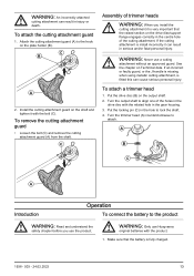
.... 3. WARNING: Clean the trimmer head cover each time you assemble new trimmer line to prevent unbalance and vibrations in ) and decrease the motor speed to decrease the risk of damage to the ground when you cut grass. 1938 - 003 - 24.02.2023 Make sure that the grass trimmer line is parallel to the ground and above the ground at an angle. To cut grass near objects. 2. Use 80 % speed when...
.... 3. WARNING: Clean the trimmer head cover each time you assemble new trimmer line to prevent unbalance and vibrations in ) and decrease the motor speed to decrease the risk of damage to the ground when you cut grass. 1938 - 003 - 24.02.2023 Make sure that the grass trimmer line is parallel to the ground and above the ground at an angle. To cut grass near objects. 2. Use 80 % speed when...
Owner Manual
Page 16
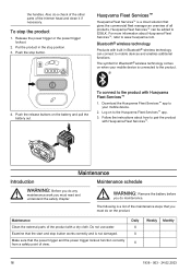
... you must do a check of the other parts of all products. Do not use water. Daily X X X Weekly Monthly 16 1938 - 003 - 24.02.2023 Husqvarna Fleet Services™ Husqvarna Fleet Services™ is a list of the maintenance steps that the power trigger and the power trigger lockout function correctly from a safety point of the product with Husqvarna Fleet Services™ 1. Download the Husqvarna Fleet Services™ app to...
... you must do a check of the other parts of all products. Do not use water. Daily X X X Weekly Monthly 16 1938 - 003 - 24.02.2023 Husqvarna Fleet Services™ Husqvarna Fleet Services™ is a list of the maintenance steps that the power trigger and the power trigger lockout function correctly from a safety point of the product with Husqvarna Fleet Services™ 1. Download the Husqvarna Fleet Services™ app to...
Owner Manual
Page 17
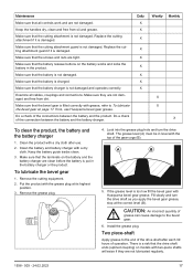
Maintenance Make sure that all cables, couplings and connections. Keep the handles dry, clean and free from dirt. Replace the cutting attachment guard if it is damaged. Make sure that the cutting attachment guard is charged. Do a check of grease can cause damage to the end of the drive shaft after use Husqvarna bevel gear grease. Clean the battery and battery charger with the grease plug at the correct level (B). Fill slowly and turn the drive shaft. CAUTION: An incorrect...
Maintenance Make sure that all cables, couplings and connections. Keep the handles dry, clean and free from dirt. Replace the cutting attachment guard if it is damaged. Make sure that the cutting attachment guard is charged. Do a check of grease can cause damage to the end of the drive shaft after use Husqvarna bevel gear grease. Clean the battery and battery charger with the grease plug at the correct level (B). Fill slowly and turn the drive shaft. CAUTION: An incorrect...

Owner Manual
Page 18
... error LED flashes Overload. The product needs servicing. Release the power trigger and the product is jammed. The power trigger and the activate button are pressed at the same time. deactivate the product. The product does not start Error LED is between 5 °C/41 °F and 45°C/113°F and away from unwanted materials. Possible action Charge the battery. Clean the cutting attachment...
... error LED flashes Overload. The product needs servicing. Release the power trigger and the product is jammed. The power trigger and the activate button are pressed at the same time. deactivate the product. The product does not start Error LED is between 5 °C/41 °F and 45°C/113°F and away from unwanted materials. Possible action Charge the battery. Clean the cutting attachment...
Owner Manual
Page 19
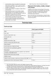
... Motor Motor type Husqvarna E-torq BLDC Speed of output shaft, 1/min 5800 Cutting width, mm 420 Weight Weight without battery, kglb 2.9/6.4 Weight including battery (BLi200) kg/lb 4.2/9.3 Noise emission 1 Sound power level, measured dB (A) 93 Sound power level, guaranteed LWAdB (A) 95 Noise levels 2 Equivalent sound pressure level at the operator's ear, measured according to ISO 22868, dB (A): Equipped with trimmer head (original) 78 Vibration levels 3 Vibration levels at a recycling station for electrical...
... Motor Motor type Husqvarna E-torq BLDC Speed of output shaft, 1/min 5800 Cutting width, mm 420 Weight Weight without battery, kglb 2.9/6.4 Weight including battery (BLi200) kg/lb 4.2/9.3 Noise emission 1 Sound power level, measured dB (A) 93 Sound power level, guaranteed LWAdB (A) 95 Noise levels 2 Equivalent sound pressure level at the operator's ear, measured according to ISO 22868, dB (A): Equipped with trimmer head (original) 78 Vibration levels 3 Vibration levels at a recycling station for electrical...

Owner Manual
Page 20
....02.2023 Radio frequency data Frequency range, GHz Output power4, max dBm Approved batteries Battery Type Battery capacity, Ah Nominal voltage, V Weight, kg (lb) Approved battery chargers Battery charger Input voltage, V Frequency, Hz Power, W 525iLK 2.4-2.4835 0 BLi 200 Lithium-ion 5.2 36 1.3 (2.9) QC330 100-240 50-60 330 Accessories Approved accessories Output shaft thread M10 Trimmer line Ø 2.0-2.4 mm Trimmer head Accessories Accessory type Cutting attachment guard, art. no.
....02.2023 Radio frequency data Frequency range, GHz Output power4, max dBm Approved batteries Battery Type Battery capacity, Ah Nominal voltage, V Weight, kg (lb) Approved battery chargers Battery charger Input voltage, V Frequency, Hz Power, W 525iLK 2.4-2.4835 0 BLi 200 Lithium-ion 5.2 36 1.3 (2.9) QC330 100-240 50-60 330 Accessories Approved accessories Output shaft thread M10 Trimmer line Ø 2.0-2.4 mm Trimmer head Accessories Accessory type Cutting attachment guard, art. no.
Owner Manual
Page 21
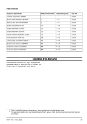
... Brush cutter attachment BCA850 Reciprocator attachment RA850 Blower attachment BA101 Edger attachment ECA850 Edger attachment ESA850 Hedge trimmer attachment HA860 Saw attachment PAB1100 Clean sweep attachment SR600-2 Bristle brush attachment BR600 Dethatcher attachment DT600 Cultivator attachment CA230 Attachment number5 Attachment group6 1 1-10 2 1-10 11 11-20 21 21-30 22 21-30 32 31-40 44 41-50 51 51-60 52 51-60 53 51-60 54 51-60 Use with 525iLK 525iLK 525iLK 525iLK 525iLK 525iLK 525iLK 525iLK 525iLK 525iLK 525iLK 525iLK...
... Brush cutter attachment BCA850 Reciprocator attachment RA850 Blower attachment BA101 Edger attachment ECA850 Edger attachment ESA850 Hedge trimmer attachment HA860 Saw attachment PAB1100 Clean sweep attachment SR600-2 Bristle brush attachment BR600 Dethatcher attachment DT600 Cultivator attachment CA230 Attachment number5 Attachment group6 1 1-10 2 1-10 11 11-20 21 21-30 22 21-30 32 31-40 44 41-50 51 51-60 52 51-60 53 51-60 54 51-60 Use with 525iLK 525iLK 525iLK 525iLK 525iLK 525iLK 525iLK 525iLK 525iLK 525iLK 525iLK 525iLK...


