

Workshop Manual
Page 13
... 13b 14 16 13c 15 17 Service tools Pos Description Used for Order No. 1 Piston stop 2 Hook for fuel filter 3 Allen key, 4 mm 4 Allen key, 4 mm Locking the crankshaft Suspending the fuel filter For M5 bolts For M5 bolts 575 29 36-01 502 50 83-01 502 50 87-01 502... 50 18-01 4 Allen key, 5 mm 5 Air gap tool 6 Clutch tool For M6 bolts Setting, ignition module Centrifugal clutch 502 50...
... 13b 14 16 13c 15 17 Service tools Pos Description Used for Order No. 1 Piston stop 2 Hook for fuel filter 3 Allen key, 4 mm 4 Allen key, 4 mm Locking the crankshaft Suspending the fuel filter For M5 bolts For M5 bolts 575 29 36-01 502 50 83-01 502 50 87-01 502... 50 18-01 4 Allen key, 5 mm 5 Air gap tool 6 Clutch tool For M6 bolts Setting, ignition module Centrifugal clutch 502 50...

Workshop Manual
Page 20
... 13 6.6 Dismantling the start/stop control A. See the "Dismantling the carburettor" chapter. 2 Loosen screw B and dismantle the stop control 1 Remove the cylinder cover and air filter. Dismantle the air filter holder. See figure 13. Parts must always be replaced if cracked or show signs of other defects. Make sure that the vibration element is...
... 13 6.6 Dismantling the start/stop control A. See the "Dismantling the carburettor" chapter. 2 Loosen screw B and dismantle the stop control 1 Remove the cylinder cover and air filter. Dismantle the air filter holder. See figure 13. Parts must always be replaced if cracked or show signs of other defects. Make sure that the vibration element is...

Workshop Manual
Page 21
...stop control in neutral. Resistance can be in "7.7 Dismantling the ignition module and flywheel". See the "Assembling the carburettor" chapter. 4 Fit air filter and cylinder cover. 6.8 Resistance test - Slide the thinner shrink tubes over each cable. When assembling (see figure 17) and in figure 16. 3... Attach the air filter holder. Slide in the stop function Dismantle the ignition module as outlined in the "off" position when the button is held down (see...
...stop control in neutral. Resistance can be in "7.7 Dismantling the ignition module and flywheel". See the "Assembling the carburettor" chapter. 4 Fit air filter and cylinder cover. 6.8 Resistance test - Slide the thinner shrink tubes over each cable. When assembling (see figure 17) and in figure 16. 3... Attach the air filter holder. Slide in the stop function Dismantle the ignition module as outlined in the "off" position when the button is held down (see...

Workshop Manual
Page 28
... 8. See figure 10. Pull the cables through the openings in place while the flywheel nut is loosened using a suitable socket wrench. Unscrew the air nozzle to the flywheel. Fig 9 Dismantle the tank unit as outlined in until the flywheel comes off the ignition cable from the guide rail and... metal hammer while at the same time pulling the flywheel outward until 1-2 threads are left to replace the ignition module. See figure 7. Dismantle the air filter, air filter holder and carburet- Dismantle the intake system, see the "Dismantling the intake system" chapter.
... 8. See figure 10. Pull the cables through the openings in place while the flywheel nut is loosened using a suitable socket wrench. Unscrew the air nozzle to the flywheel. Fig 9 Dismantle the tank unit as outlined in until the flywheel comes off the ignition cable from the guide rail and... metal hammer while at the same time pulling the flywheel outward until 1-2 threads are left to replace the ignition module. See figure 7. Dismantle the air filter, air filter holder and carburet- Dismantle the intake system, see the "Dismantling the intake system" chapter.

Workshop Manual
Page 29
...29 Fit the intake system as outlined in "7.14 Assembling the intake system", the tank unit as outlined in "7.16 tank unit", and the air filter as outlined in position. Do not tighten the screws. NOTE! Take care that the cable channel is positioned correctly under the ignition module so ...at a tightening torque of 4.5- 6 Nm. Turn the flywheel until the key fits into the holder on the partition wall. 7 Then fit: • The air nozzle • The guide rail and press the cable in "Assembling the carburettor". 6 Press the ignition lead into the key slot on the ignition module...
...29 Fit the intake system as outlined in "7.14 Assembling the intake system", the tank unit as outlined in "7.16 tank unit", and the air filter as outlined in position. Do not tighten the screws. NOTE! Take care that the cable channel is positioned correctly under the ignition module so ...at a tightening torque of 4.5- 6 Nm. Turn the flywheel until the key fits into the holder on the partition wall. 7 Then fit: • The air nozzle • The guide rail and press the cable in "Assembling the carburettor". 6 Press the ignition lead into the key slot on the ignition module...

Workshop Manual
Page 33
...screws. Push the tank back in "Dismantling the carburettor". See figure 24. Fig 25b Fig 26 Repair Instructions English - 33 3 Dismantle the air filter, the filter holder, the cable from the holder on the partition wall. Knock out the POP-out window using the POP-out hole and the fuel hose... hole. Fit the carburettor, the filter holder and the air filter as outlined in position. Pull up and then outward. Always use original spare parts. 7.13 Assembling the intake system 1 Assemble the ...
...screws. Push the tank back in "Dismantling the carburettor". See figure 24. Fig 25b Fig 26 Repair Instructions English - 33 3 Dismantle the air filter, the filter holder, the cable from the holder on the partition wall. Knock out the POP-out window using the POP-out hole and the fuel hose... hole. Fit the carburettor, the filter holder and the air filter as outlined in position. Pull up and then outward. Always use original spare parts. 7.13 Assembling the intake system 1 Assemble the ...

Workshop Manual
Page 36
.... 3 Loosen the suction hose A, the return hose B, and the tank bleeding hose C. The lug on both sides. English Fig 37 Fig 34 4 Remove the air filter holder. Separate the connector by pressing down the lug to release the carburettor. Loosen the fuel hose, D. Lift out the carburettor. Let the... air filter holder remain in place in the cabling for the stop button. See figure 34. 5 NOTE! See figure 36. See figure 37. 36 - See figure 34...
.... 3 Loosen the suction hose A, the return hose B, and the tank bleeding hose C. The lug on both sides. English Fig 37 Fig 34 4 Remove the air filter holder. Separate the connector by pressing down the lug to release the carburettor. Loosen the fuel hose, D. Lift out the carburettor. Let the... air filter holder remain in place in the cabling for the stop button. See figure 34. 5 NOTE! See figure 36. See figure 37. 36 - See figure 34...

Workshop Manual
Page 41
...the carburettor in the rubber grommets, G. Hook on the throttle cable (E) in its mountings on the air filter holder. See figure 46. Fig 46 3 Position the guide taps on the air filter holder in the rubber mounting. Attach the tank bleeding hose, C. See figure 46. Attach the pressure... hooks in its mounting on the intake bellows. Make sure that the fuel and return hoses are correctly fitted: • Position the air filter holder against the carburettor. • Make sure the carburettor cover's intake channel is fitted to its mounting on the intake system. 2...
...the carburettor in the rubber grommets, G. Hook on the throttle cable (E) in its mountings on the air filter holder. See figure 46. Fig 46 3 Position the guide taps on the air filter holder in the rubber mounting. Attach the tank bleeding hose, C. See figure 46. Attach the pressure... hooks in its mounting on the intake bellows. Make sure that the fuel and return hoses are correctly fitted: • Position the air filter holder against the carburettor. • Make sure the carburettor cover's intake channel is fitted to its mounting on the intake system. 2...

Workshop Manual
Page 43
... parts. Fig 56 Fig 57 Repair Instructions English - 43 See figure 51. 6. The two short screws are on the throttle cable E in hole L. Assemble the air filter and cylinder cover. See "Assembling the tank unit". •Cylinder cover. See figure 55. See figure 53. 5. See the Operator's Manual. •Tank unit and...
... parts. Fig 56 Fig 57 Repair Instructions English - 43 See figure 51. 6. The two short screws are on the throttle cable E in hole L. Assemble the air filter and cylinder cover. See "Assembling the tank unit". •Cylinder cover. See figure 55. See figure 53. 5. See the Operator's Manual. •Tank unit and...

Workshop Manual
Page 44
Tighten the fuel hose on the fuel pump. 3. Loosen suction hose C and return hose from the filter holder. Assemble the air filter and cylinder cover. English Use suitable pliers with your fingers. Fig 58 7.20 Replacing the fuel pump (Purge) Dismantle 1. Snap ...See figure 58. Dismantle the cylinder cover and the air filter. 2. Repair Instructions 7.18 Replacing the fuel filter NOTE! Fluted pliers may not be removed from the tank unit and pull away the filter A. Fit the return and suction hose on the filter side with a smooth cutting face and loosen the hose...
Tighten the fuel hose on the fuel pump. 3. Loosen suction hose C and return hose from the filter holder. Assemble the air filter and cylinder cover. English Use suitable pliers with your fingers. Fig 58 7.20 Replacing the fuel pump (Purge) Dismantle 1. Snap ...See figure 58. Dismantle the cylinder cover and the air filter. 2. Repair Instructions 7.18 Replacing the fuel filter NOTE! Fluted pliers may not be removed from the tank unit and pull away the filter A. Fit the return and suction hose on the filter side with a smooth cutting face and loosen the hose...

Workshop Manual
Page 57
... operating faults are listed to the left while the probable fault alternatives are listed to start Air filter blocked Choke does not work Worn choke axle Worn choke valve Blocked fuel filter Blocked fuel line Piston ring is stuck Blocked impulse channel The carburettor leaks fuel Loose or... crankcase Idling (low speed) Does not idle Leaking inlet hose (rubber) Loose carburettor mounting Loose or faulty fuel pipe Blocked fuel filter Blocked fuel line Tank ventilator blocked The throttle valve shaft is inert Throttle stay is binding Defective throttle return spring Bent valve axle stop...
... operating faults are listed to the left while the probable fault alternatives are listed to start Air filter blocked Choke does not work Worn choke axle Worn choke valve Blocked fuel filter Blocked fuel line Piston ring is stuck Blocked impulse channel The carburettor leaks fuel Loose or... crankcase Idling (low speed) Does not idle Leaking inlet hose (rubber) Loose carburettor mounting Loose or faulty fuel pipe Blocked fuel filter Blocked fuel line Tank ventilator blocked The throttle valve shaft is inert Throttle stay is binding Defective throttle return spring Bent valve axle stop...

Workshop Manual
Page 58
...incorrectly assembled Loose diaphragm Hole in diaphragm Leaking diaphragm/cover plate Acceleration and retardation Does not accelerate Blocked air filter Tank venting clogged Blocked fuel filter Blocked fuel line Loose or faulty fuel pipe Blocked impulse channel The cover on a specific component or...engine stops when releasing the throttle Faulty pump diaphragm Control system set too high Control system sticking Faulty diffuser jet Blocked air filter Faulty pump diaphragm Faulty diffuser jet 8.2 Troubleshooting methods In addition to faults given in respective sections and are as follows...
...incorrectly assembled Loose diaphragm Hole in diaphragm Leaking diaphragm/cover plate Acceleration and retardation Does not accelerate Blocked air filter Tank venting clogged Blocked fuel filter Blocked fuel line Loose or faulty fuel pipe Blocked impulse channel The cover on a specific component or...engine stops when releasing the throttle Faulty pump diaphragm Control system set too high Control system sticking Faulty diffuser jet Blocked air filter Faulty pump diaphragm Faulty diffuser jet 8.2 Troubleshooting methods In addition to faults given in respective sections and are as follows...
Parts List
Page 5
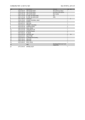
... Part no. Description 1 522 67 50-01 AIR FILTER ASSY 1 522 67 50-02 AIR FILTER ASSY 1 522 67 50-03 AIR FILTER ASSY 2 505 12 70-03 FILTER HOLDER ASSY 2 505 12 70-04 FILTER HOLDER ASSY 3 505 17 69-01 SHACKLE 4 510 01 72-01 CHOKE CONTROL ASSY 5 505 15 62-01 SCREW 6 525 58 81... 92-01 SEALING 17 525 61 90-01 SEALING 18 523 05 68-01 FUEL HOSE 19 . TBD 20 577 53 64-01 WIRING ASSY 562 XP/XPG, 2013-01 Remark NYLON 80 µm black NYLON 44 µm yellow FELT white...
... Part no. Description 1 522 67 50-01 AIR FILTER ASSY 1 522 67 50-02 AIR FILTER ASSY 1 522 67 50-03 AIR FILTER ASSY 2 505 12 70-03 FILTER HOLDER ASSY 2 505 12 70-04 FILTER HOLDER ASSY 3 505 17 69-01 SHACKLE 4 510 01 72-01 CHOKE CONTROL ASSY 5 505 15 62-01 SCREW 6 525 58 81... 92-01 SEALING 17 525 61 90-01 SEALING 18 523 05 68-01 FUEL HOSE 19 . TBD 20 577 53 64-01 WIRING ASSY 562 XP/XPG, 2013-01 Remark NYLON 80 µm black NYLON 44 µm yellow FELT white...
Parts List
Page 13
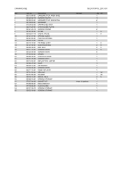
...03 CRANKCASE ASSY 6 522 74 29-01 CHAIN GUIDE PLATE 7 503 21 26-16 SCREW IHPANM 8 537 40 35-01 FILTER 9 530 02 61-19 CHECK VALVE 10 537 21 07-01 SPRING GUIDE 11 503 43 65-01 POSITION SPRING 12 ... SCREW IHSCT 22 505 12 58-01 DEFLECTION LIMITER 23 503 89 47-03 SNAP 24 520 29 12-01 AIR NOZZLE 25 510 02 06-01 SCREW IHSCM 26 544 11 12-01 TANK CAP ASSY 27 537 21 50...-01 ENCLOSED KIT 33 577 38 68-01 CHAIN GUIDE 34 503 21 28-13 SCREW CCRPANT 35 526 22 18-01 SCREW CITXPANT 562 XP/XPG, 2013-01 Remark A=set of gaskets Qty Kit 1 4 2 1 1 1 2 15 15 1 1 1 15 25 25 25 5 1 1 1 1 ...
...03 CRANKCASE ASSY 6 522 74 29-01 CHAIN GUIDE PLATE 7 503 21 26-16 SCREW IHPANM 8 537 40 35-01 FILTER 9 530 02 61-19 CHECK VALVE 10 537 21 07-01 SPRING GUIDE 11 503 43 65-01 POSITION SPRING 12 ... SCREW IHSCT 22 505 12 58-01 DEFLECTION LIMITER 23 503 89 47-03 SNAP 24 520 29 12-01 AIR NOZZLE 25 510 02 06-01 SCREW IHSCM 26 544 11 12-01 TANK CAP ASSY 27 537 21 50...-01 ENCLOSED KIT 33 577 38 68-01 CHAIN GUIDE 34 503 21 28-13 SCREW CCRPANT 35 526 22 18-01 SCREW CITXPANT 562 XP/XPG, 2013-01 Remark A=set of gaskets Qty Kit 1 4 2 1 1 1 2 15 15 1 1 1 15 25 25 25 5 1 1 1 1 ...


