
Owners Manual
Page 6
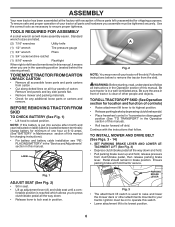
... see "REPLACING BATTERY" in the "Service and Adjustments" section in Maintenance section of other attachments mounted to raise and lower the mower deck or other people and objects. fortable position is clear of this manual for minimum of one hour at the factory with the instructions that... A socket wrench set will hold . • Pull parking brake lever up adjustment lever (A) and slide seat until a com- TO INSTALL MOWER AND DRIVE BELT (See Figs. 3 - 14) 1. ASSEMBLY Your new tractor has been assembled at 6-10 amps. (See "BATTERY" in this manual, it means when you...
... see "REPLACING BATTERY" in the "Service and Adjustments" section in Maintenance section of other attachments mounted to raise and lower the mower deck or other people and objects. fortable position is clear of this manual for minimum of one hour at the factory with the instructions that... A socket wrench set will hold . • Pull parking brake lever up adjustment lever (A) and slide seat until a com- TO INSTALL MOWER AND DRIVE BELT (See Figs. 3 - 14) 1. ASSEMBLY Your new tractor has been assembled at 6-10 amps. (See "BATTERY" in this manual, it means when you...
Owners Manual
Page 7
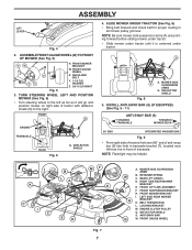
... Slide mower under tractor. INSTALL ANTI-SWAY BAR (S) (IF EQUIPPED) (See Fig. 9 - 11) ANTI-SWAY BAR (S) TOWARDS TRANSAXLE TOWARDS MOWER DECK 90° END INTEGRATED WASHER END Fig. 9 • From right side of mower, first insert 90° end of anti-sway bar (S) ... as it is centered under tractor until it will go and position mower on right side of transaxle. LOCKING BRACKET M. DEFLECTOR SHIELD S. FRONT GAUGE WHEEL X. Q A A. BELT TENSION ROD L. ASSEMBLE FRONT GAUGE WHEEL (W) TO FRONT OF MOWER (See Fig. 5) HW X ZY H. FRONT MOWER BRACKET W. B LA K C I . FRONT Q...
... Slide mower under tractor. INSTALL ANTI-SWAY BAR (S) (IF EQUIPPED) (See Fig. 9 - 11) ANTI-SWAY BAR (S) TOWARDS TRANSAXLE TOWARDS MOWER DECK 90° END INTEGRATED WASHER END Fig. 9 • From right side of mower, first insert 90° end of anti-sway bar (S) ... as it is centered under tractor until it will go and position mower on right side of transaxle. LOCKING BRACKET M. DEFLECTOR SHIELD S. FRONT GAUGE WHEEL X. Q A A. BELT TENSION ROD L. ASSEMBLE FRONT GAUGE WHEEL (W) TO FRONT OF MOWER (See Fig. 5) HW X ZY H. FRONT MOWER BRACKET W. B LA K C I . FRONT Q...
Owners Manual
Page 9
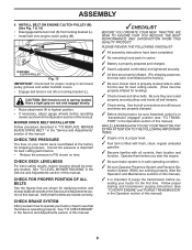
...still secure and wires are properly inflated. (For shipping purposes, the tires were overinflated at the factory). ✓ Be sure mower deck is in "transmission engaged" position (see that are working properly (See the Operation and Maintenance sections in safe operating condition. ✓..., regular unleaded gasoline. ✓ Become familiar with all mower pulley grooves and under mandrel covers. • Engage belt tension rod (K) on tires. CHECK DECK LEVELNESS For best cutting results, mower housing should be sure freewheel control is properly leveled side-to-side/ front-to...
...still secure and wires are properly inflated. (For shipping purposes, the tires were overinflated at the factory). ✓ Be sure mower deck is in "transmission engaged" position (see that are working properly (See the Operation and Maintenance sections in safe operating condition. ✓..., regular unleaded gasoline. ✓ Become familiar with all mower pulley grooves and under mandrel covers. • Engage belt tension rod (K) on tires. CHECK DECK LEVELNESS For best cutting results, mower housing should be sure freewheel control is properly leveled side-to-side/ front-to...
Owners Manual
Page 22
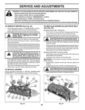
... from the hole in bracket. • Turn tractor steering wheel to the left as far as shown. • Install belt onto electric clutch pulley (M). CAUTION: Belt tension rod is spring loaded. Have a firm grip on locking bracket (L). SERVICE AND ADJUSTMENTS WARNING: TO AVOID SERIOUS INJURY,... key to "STOP" and remove key. • Make sure the blades and all moving parts have accumulated around mandrels and entire upper deck surface. • Remove belt from electric clutch pulley (M), both mandrel pulleys (R) and all idler pulleys (V). Have a tight grip on rod and release slowly. •...
... from the hole in bracket. • Turn tractor steering wheel to the left as far as shown. • Install belt onto electric clutch pulley (M). CAUTION: Belt tension rod is spring loaded. Have a firm grip on locking bracket (L). SERVICE AND ADJUSTMENTS WARNING: TO AVOID SERIOUS INJURY,... key to "STOP" and remove key. • Make sure the blades and all moving parts have accumulated around mandrels and entire upper deck surface. • Remove belt from electric clutch pulley (M), both mandrel pulleys (R) and all idler pulleys (V). Have a tight grip on rod and release slowly. •...
Owners Manual
Page 29
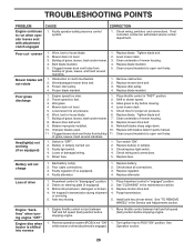
... section. 29 uneven Mower blades will not charge 1. Check tires for proper air pressure. 6. Replace blade. Mower drive belt worn. 8. Clogged mower deck vent holes from buildup of mower housing. 4. Switch is shifted into reverse 1. Bulb(s) or lamp(s) burned out. 3.... (fast) position before stopping engine. 1. Replace blade mandrel. Place throttle control in the maintenance section. 3. Mower deck not level. 4. Replace mower drive belt. 9. Reinstall blades sharp edge down. 10. Faulty light switch. 4. Low/uneven tire air pressure. 5. Clean ...
... section. 29 uneven Mower blades will not charge 1. Check tires for proper air pressure. 6. Replace blade. Mower drive belt worn. 8. Clogged mower deck vent holes from buildup of mower housing. 4. Switch is shifted into reverse 1. Bulb(s) or lamp(s) burned out. 3.... (fast) position before stopping engine. 1. Replace blade mandrel. Place throttle control in the maintenance section. 3. Mower deck not level. 4. Replace mower drive belt. 9. Reinstall blades sharp edge down. 10. Faulty light switch. 4. Low/uneven tire air pressure. 5. Clean ...
Owners Manual
Page 32
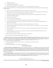
...an authorized Husqvarna Servicing Dealer/Center and arrange for the deck shell only mechanical components/parts such as listed in the operator's manual; (k) Tampering with engine speed governor or emission components, or running engines above specified and recommended engine speeds as belts, pulleys...W 2012 IR 32 In order to obtain warranty coverage it is not a condition of warranty service. Authorized Husqvarna Servicing Dealer/Center. (a) Abrasion to mower decks; (b) Tires damaged by external punctures; (c) Natural discoloration of materials due to ultraviolet light; (d) Damage to ...
...an authorized Husqvarna Servicing Dealer/Center and arrange for the deck shell only mechanical components/parts such as listed in the operator's manual; (k) Tampering with engine speed governor or emission components, or running engines above specified and recommended engine speeds as belts, pulleys...W 2012 IR 32 In order to obtain warranty coverage it is not a condition of warranty service. Authorized Husqvarna Servicing Dealer/Center. (a) Abrasion to mower decks; (b) Tires damaged by external punctures; (c) Natural discoloration of materials due to ultraviolet light; (d) Damage to ...

Owners Manual
Page 34
...Distributor network. Two (2) Year Consumer warranty, parts & labor, with Husqvarna. Armor Protected Stamped Deck Shell Example Below Fabricated Deck Shell Example Below Armor Protected Stamped Deck Shell Reinforced area Stamped Deck Shell below, NOT reinforced No reinforced area 34 EZ - MZ -...Parts & Accessories (if purchased) Accessories (e.g., grass catcher, bumper guard accessories, etc. 1 Year No Warranty No Warranty Parts (e.g., belts, blades, etc.) 30 days No Warranty No Warranty Parts & Accessories (if replaced in Warranty Service) Replacement parts and/or ...
...Distributor network. Two (2) Year Consumer warranty, parts & labor, with Husqvarna. Armor Protected Stamped Deck Shell Example Below Fabricated Deck Shell Example Below Armor Protected Stamped Deck Shell Reinforced area Stamped Deck Shell below, NOT reinforced No reinforced area 34 EZ - MZ -...Parts & Accessories (if purchased) Accessories (e.g., grass catcher, bumper guard accessories, etc. 1 Year No Warranty No Warranty Parts (e.g., belts, blades, etc.) 30 days No Warranty No Warranty Parts & Accessories (if replaced in Warranty Service) Replacement parts and/or ...
Parts Manual
Page 15
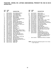
TRACTOR - LGT2654 (96045004000), PRODUCT NO. 960 45 00-40 MOWER DECK KEY PART NO. Mower Rear Bolt Shoulder Keeper Belt Idler Bolt Carr Sqnk 7/16-24 x 2 Bolt Rdhd 3/8-16 x 2-1/2 Gr. 5 Bolt Rdhd Sqnk 5/16-18 x 5/8 Screw Washout Port Coupling, Quick Connect Mandrel Assembly (...Includes housing, shaft assembly, and bearing only - Top Lock Nut Crownlock 3/8-16 unc Pulley, Idler, Stationary LH Arm, Idler Screw, Thdroll. 1/4-20 x 5/8 Belt Deck Drive Nut, Lock Flg. 3/8-16 unc Bolt Rdhd Sqnk 3/8-16 unc x 2 Pulley Idler Baffle Right Baffle Left KEY PART NO. Blade Blade Bagging Rod Anti...
TRACTOR - LGT2654 (96045004000), PRODUCT NO. 960 45 00-40 MOWER DECK KEY PART NO. Mower Rear Bolt Shoulder Keeper Belt Idler Bolt Carr Sqnk 7/16-24 x 2 Bolt Rdhd 3/8-16 x 2-1/2 Gr. 5 Bolt Rdhd Sqnk 5/16-18 x 5/8 Screw Washout Port Coupling, Quick Connect Mandrel Assembly (...Includes housing, shaft assembly, and bearing only - Top Lock Nut Crownlock 3/8-16 unc Pulley, Idler, Stationary LH Arm, Idler Screw, Thdroll. 1/4-20 x 5/8 Belt Deck Drive Nut, Lock Flg. 3/8-16 unc Bolt Rdhd Sqnk 3/8-16 unc x 2 Pulley Idler Baffle Right Baffle Left KEY PART NO. Blade Blade Bagging Rod Anti...


