

Owners Manual
Page 6
...sections in "transmission engaged" position (see that all connections are still secure and wires are shown for replacing motion and mower blade drive belts in safe operating condition. ✓ Be sure Operator Presence System and Reverse Op- eration System (ROS) are properly inflated. (For ...cutting results, mower housing should be sure freewheel control is filled with fresh, clean, regular unleaded gasoline. ✓ Become familiar with all belt keepers. ✓ Check wiring. CHECK BRAKE SYSTEM After you start the engine. ✓ Be sure brake system is important for the ...
...sections in "transmission engaged" position (see that all connections are still secure and wires are shown for replacing motion and mower blade drive belts in safe operating condition. ✓ Be sure Operator Presence System and Reverse Op- eration System (ROS) are properly inflated. (For ...cutting results, mower housing should be sure freewheel control is filled with fresh, clean, regular unleaded gasoline. ✓ Become familiar with all belt keepers. ✓ Check wiring. CHECK BRAKE SYSTEM After you start the engine. ✓ Be sure brake system is important for the ...

Owners Manual
Page 14
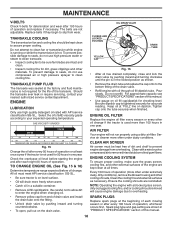
... C Check/Replace Mower Blades T Lubrication Chart 0 Check Battery Level R Clean Battery and Terminals Clean Debris Off Steering Plate Check Transaxle Cooling Check Mower Levelness Check V-Belts Check Engine Oil Level Change Engine Oil (with maintenance-free battery. 5 - IMPORTANT: DO NOT OIL OR GREASE THE PIVOT POINTS WHICH HAVE SPECIAL NYLON BEARINGS... The warranty on this manual. • At least once a year you should replace the spark plug, clean or replace air filter, and check blades and belts for proper operation.
... C Check/Replace Mower Blades T Lubrication Chart 0 Check Battery Level R Clean Battery and Terminals Clean Debris Off Steering Plate Check Transaxle Cooling Check Mower Levelness Check V-Belts Check Engine Oil Level Change Engine Oil (with maintenance-free battery. 5 - IMPORTANT: DO NOT OIL OR GREASE THE PIVOT POINTS WHICH HAVE SPECIAL NYLON BEARINGS... The warranty on this manual. • At least once a year you should replace the spark plug, clean or replace air filter, and check blades and belts for proper operation.
Owners Manual
Page 16
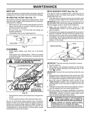
... deterioration and wear after 100 hours of operation, whichever occurs first. The belts are reinstalled. To prevent damage to seals, do not use high pressure water or steam to clean transaxle. • Inspect cooling fan to be kept ... cooling. Be sure dipstick cap is hot. Check the crankcase oil level before oil change if the tractor is not required for accurate reading. Replace belts if they begin to prevent engine damage from wear. Tighten cap onto the tube securely when finished. Ensure the cooling shrouds are not adjustable. Spark...
... deterioration and wear after 100 hours of operation, whichever occurs first. The belts are reinstalled. To prevent damage to seals, do not use high pressure water or steam to clean transaxle. • Inspect cooling fan to be kept ... cooling. Be sure dipstick cap is hot. Check the crankcase oil level before oil change if the tractor is not required for accurate reading. Replace belts if they begin to prevent engine damage from wear. Tighten cap onto the tube securely when finished. Ensure the cooling shrouds are not adjustable. Spark...
Owners Manual
Page 17
... and plug fuel line sections. • Place new fuel filter in position in the Fast " " position. Debris can restrict clutch/brake pedal shaft movement, causing belt slip and loss of your garden hose. 4. Turn the ignition key to the CAUTION: PINCH STOP position to the "DISENGAGED" position. transmission will shorten the...
... and plug fuel line sections. • Place new fuel filter in position in the Fast " " position. Debris can restrict clutch/brake pedal shaft movement, causing belt slip and loss of your garden hose. 4. Turn the ignition key to the CAUTION: PINCH STOP position to the "DISENGAGED" position. transmission will shorten the...
Owners Manual
Page 18
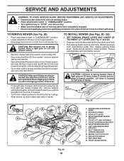
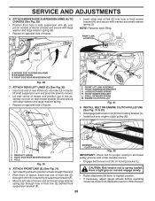
... MOWER (See Figs. 20 - 28) 1. Pedal should remain in "DISENGAGED" position. • Lower attachment lift lever to its lowest position. • Disengage belt tension rod (K) from lock bracket (L). Ensure parking brake will be spring loaded. LIFT LEVER Fig. 22 LB A K C I . RIGHT SIDE REAR MOWER BRACKET...where it will go. • Slide mower out from mower - Have a tight grip on rod and release slowly. • Remove mower belt from electric clutch pulley (M). • Disconnect front link (E) from under right side of mower and disconnect mower suspen- FRONT LIFT LINK ASSEMBLY F....
... MOWER (See Figs. 20 - 28) 1. Pedal should remain in "DISENGAGED" position. • Lower attachment lift lever to its lowest position. • Disengage belt tension rod (K) from lock bracket (L). Ensure parking brake will be spring loaded. LIFT LEVER Fig. 22 LB A K C I . RIGHT SIDE REAR MOWER BRACKET...where it will go. • Slide mower out from mower - Have a tight grip on rod and release slowly. • Remove mower belt from electric clutch pulley (M). • Disconnect front link (E) from under right side of mower and disconnect mower suspen- FRONT LIFT LINK ASSEMBLY F....
Owners Manual
Page 19
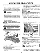
.... 24) • Turn steering wheel to the left rear tire in rear mower bracket (D). SLIDE MOWER UNDER TRACTOR (See Fig. 25) • Bring belt forward and check belt for anti-sway bar will go and position mower on right side of tractor with small washer and small retainer spring as needed to...
.... 24) • Turn steering wheel to the left rear tire in rear mower bracket (D). SLIDE MOWER UNDER TRACTOR (See Fig. 25) • Bring belt forward and check belt for anti-sway bar will go and position mower on right side of tractor with small washer and small retainer spring as needed to...
Owners Manual
Page 20
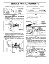
... REAR LIFT LINKS (C) (See Fig. 30) • Insert rod end of this manual. 20 M D C. M. ENGINE CLUTCH PULLEY Fig. 32 IMPORTANT: Check belt for proper routing in the Operation section of rear lift link (C) into hole in front mower bracket (H) and secure with washer and small retainer spring...8226; Lift rear corner of mower and position slot in link as shown in all mower pulley grooves and under mandrel covers. • Engage belt tension rod (K) on opposite side of tractor chassis and secure with large washer and large retainer spring. • Repeat on locking bracket (L). ...
... REAR LIFT LINKS (C) (See Fig. 30) • Insert rod end of this manual. 20 M D C. M. ENGINE CLUTCH PULLEY Fig. 32 IMPORTANT: Check belt for proper routing in the Operation section of rear lift link (C) into hole in front mower bracket (H) and secure with washer and small retainer spring...8226; Lift rear corner of mower and position slot in link as shown in all mower pulley grooves and under mandrel covers. • Engage belt tension rod (K) on opposite side of tractor chassis and secure with large washer and large retainer spring. • Repeat on locking bracket (L). ...
Owners Manual
Page 21
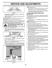
...highest position. Protect your lawn appears unevenly cut, determine which may have accumulated around idler pulleys (V) as shown. • Install belt onto electric clutch pulley (M). TO LEVEL MOWER Make sure tires are satisfied with heavy cloth. • Raise mower to its lowest position.... SIDE-TO-SIDE ADJUSTMENT (See Fig. 35) • With all tires properly inflated, park tractor on both sides. 21 CAUTION: Belt tension rod is not adjusted properly. CAUTION: Blades are over or under inflated, it is held in "transmission disengaged" position. Securely tighten...
...highest position. Protect your lawn appears unevenly cut, determine which may have accumulated around idler pulleys (V) as shown. • Install belt onto electric clutch pulley (M). TO LEVEL MOWER Make sure tires are satisfied with heavy cloth. • Raise mower to its lowest position.... SIDE-TO-SIDE ADJUSTMENT (See Fig. 35) • With all tires properly inflated, park tractor on both sides. 21 CAUTION: Belt tension rod is not adjusted properly. CAUTION: Blades are over or under inflated, it is held in "transmission disengaged" position. Securely tighten...
Owners Manual
Page 22
...lower than the rear tip. • Hold adjustment nut in all pulley grooves and inside the belt keeper. 4. For assistance, there is inside all belt guides and keepers. 2. BELT REMOVAL - 1. Remove belt downward from tractor. Installbeltthroughstationaryidler(C)andclutchingidler(D). 6. Reconnect clutch harness (A). 8. B A NOTE: Each ...MOWER Fig. 37 22 CAUTION: Blades are equal. Remove mower (See "TO REMOVE MOWER" section in this manual). Pull belt toward front of tractor, off the steering plate (H) and remove from engine pulley and around electric clutch (G). 8. Reinstall ...
...lower than the rear tip. • Hold adjustment nut in all pulley grooves and inside the belt keeper. 4. For assistance, there is inside all belt guides and keepers. 2. BELT REMOVAL - 1. Remove belt downward from tractor. Installbeltthroughstationaryidler(C)andclutchingidler(D). 6. Reconnect clutch harness (A). 8. B A NOTE: Each ...MOWER Fig. 37 22 CAUTION: Blades are equal. Remove mower (See "TO REMOVE MOWER" section in this manual). Pull belt toward front of tractor, off the steering plate (H) and remove from engine pulley and around electric clutch (G). 8. Reinstall ...

Owners Manual
Page 25
... surfaces. Store in a clean, dry area. • Clean entire tractor (See "CLEANING" in the Maintenance section of this manual). • Inspect and replace belts, if necessary (See belt replacement instructions in the Service and Adjustments section of this manual). • Lubricate as shown in the Maintenance section of this manual). • After...
... surfaces. Store in a clean, dry area. • Clean entire tractor (See "CLEANING" in the Maintenance section of this manual). • Inspect and replace belts, if necessary (See belt replacement instructions in the Service and Adjustments section of this manual). • Lubricate as shown in the Maintenance section of this manual). • After...
Owners Manual
Page 27
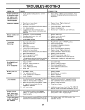
... in "FAST" position. 2. Purge transmission. 5. Mower deck not level. 3. Obstruction in "disengaged" position. 2. Replace mower drive belt. 3. Replace mower drive belt. 9. Check/clean all connections. 3. Freewheel control in clutch mechanism. 2. Air trapped in the Service and Adjustments section. See "TO...WHEEL" in transmission during shipment or servicing. 5. Clogged mower deck vent holes from buildup 11. Replace blade. Mower drive belt worn. 8. Install axle key at rear wheel. Move throttle control between half and full speed (fast) position before stopping...
... in "FAST" position. 2. Purge transmission. 5. Mower deck not level. 3. Obstruction in "disengaged" position. 2. Replace mower drive belt. 3. Replace mower drive belt. 9. Check/clean all connections. 3. Freewheel control in clutch mechanism. 2. Air trapped in the Service and Adjustments section. See "TO...WHEEL" in transmission during shipment or servicing. 5. Clogged mower deck vent holes from buildup 11. Replace blade. Mower drive belt worn. 8. Install axle key at rear wheel. Move throttle control between half and full speed (fast) position before stopping...

Owners Manual
Page 35
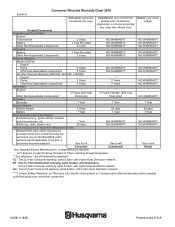
... Rod, Brake Ring E Rod, Brake, Park Cover, Foot Pedal Bolt Pulley Idler Flat Lock Nut 3/8-16 Idler V-Groove 910" Offset V-Belt, Drive Shaft Asm. Pedal Control Bearing Nylon Knob Control Cruise Pedal Forward Pad Pedal Reverse Bracket Pulley Idler Retainer Spring Clip Handle Washer 21/32... Spring Pin Cotter 1/8 x 3/4 Retainer Clip Spring, Return, Clutch Rod Pedal Control Nut Push Latch Brake Parking Keeper Belt Centerspan KEY PART NO. inches 1 inch = 25.4 mm 35 YTH23V48 (96043011000), PRODUCT NO. 960 43 01-10 DRIVE KEY PART NO. TRACTOR - Bracket Mount Torque Washer Hardened NOTE:...
... Rod, Brake Ring E Rod, Brake, Park Cover, Foot Pedal Bolt Pulley Idler Flat Lock Nut 3/8-16 Idler V-Groove 910" Offset V-Belt, Drive Shaft Asm. Pedal Control Bearing Nylon Knob Control Cruise Pedal Forward Pad Pedal Reverse Bracket Pulley Idler Retainer Spring Clip Handle Washer 21/32... Spring Pin Cotter 1/8 x 3/4 Retainer Clip Spring, Return, Clutch Rod Pedal Control Nut Push Latch Brake Parking Keeper Belt Centerspan KEY PART NO. inches 1 inch = 25.4 mm 35 YTH23V48 (96043011000), PRODUCT NO. 960 43 01-10 DRIVE KEY PART NO. TRACTOR - Bracket Mount Torque Washer Hardened NOTE:...
Owners Manual
Page 37
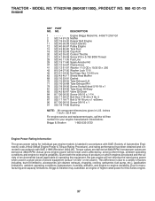
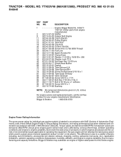
..., ambient operating conditions and engine-to -engine variability. Engine Briggs Model No. 445577-2187-G1 2 532 14 97-23 Muffler 9 532 19 43-20 Keeper Belt Engine 11 532 40 00-08 Clutch Electric 12 532 40 50-97 Pulley Engine 15 532 43 80-80 Tank Fuel 18 532 43... for your engine manufacturer listed below: Briggs & Stratton 1-800-233-3723 Engine Power Rating Information The gross power rating for this Series engine. 37 NO. YTH23V48 (96043011000), PRODUCT NO. 960 43 01-10 ENGINE KEY PART NO. Torque values are placed and the variety of environmental issues applicable to operating the...
..., ambient operating conditions and engine-to -engine variability. Engine Briggs Model No. 445577-2187-G1 2 532 14 97-23 Muffler 9 532 19 43-20 Keeper Belt Engine 11 532 40 00-08 Clutch Electric 12 532 40 50-97 Pulley Engine 15 532 43 80-80 Tank Fuel 18 532 43... for your engine manufacturer listed below: Briggs & Stratton 1-800-233-3723 Engine Power Rating Information The gross power rating for this Series engine. 37 NO. YTH23V48 (96043011000), PRODUCT NO. 960 43 01-10 ENGINE KEY PART NO. Torque values are placed and the variety of environmental issues applicable to operating the...

Owners Manual
Page 41
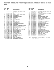
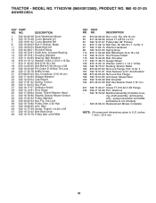
...-80 Pulley, Idler, 4.50 Hub 43 532 19 60-65 Arm, Idler 46 532 13 77-29 Screw, Thdroll. 1/4-20 x 5/8 47 532 19 72-42 Belt Deck Drive 48 532 19 73-79 Pulley Idler 4.50 RAW KEY PART NO. TRACTOR - NO. w/Lower Bearing 14 532 18 72-81 Housing, Mandrel... only - Blade 11 532 18 00-54 Blade High Lift 12 532 40 48-51 Rod Anti-Sway 13 532 18 72-91 Shaft Asm. YTH23V48 (96043011000), PRODUCT NO. 960 43 01-10 MOWER DECK KEY PART NO.
...-80 Pulley, Idler, 4.50 Hub 43 532 19 60-65 Arm, Idler 46 532 13 77-29 Screw, Thdroll. 1/4-20 x 5/8 47 532 19 72-42 Belt Deck Drive 48 532 19 73-79 Pulley Idler 4.50 RAW KEY PART NO. TRACTOR - NO. w/Lower Bearing 14 532 18 72-81 Housing, Mandrel... only - Blade 11 532 18 00-54 Blade High Lift 12 532 40 48-51 Rod Anti-Sway 13 532 18 72-91 Shaft Asm. YTH23V48 (96043011000), PRODUCT NO. 960 43 01-10 MOWER DECK KEY PART NO.
Owners Manual
Page 45
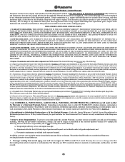
... RENTAL use will assign the transmission / transaxle manufacturer's warranty or any questions concerning transmission / transaxle warranty coverage, contact Husqvarna directly at the time of the above listed manufacturers (for the transmission / transaxle to the ultimate purchaser or to the... without limitation spark plugs, bulbs, filters, lubricants, starter cords, belts, blades, and blade adapters. (d) Emissions Control Components. THIS LIMITED WARRANTY IS THE SOLE EXPRESS WARRANTY PROVIDED BY HUSQVARNA. All such claims must demonstrate reasonable care and use and maintenance ...
... RENTAL use will assign the transmission / transaxle manufacturer's warranty or any questions concerning transmission / transaxle warranty coverage, contact Husqvarna directly at the time of the above listed manufacturers (for the transmission / transaxle to the ultimate purchaser or to the... without limitation spark plugs, bulbs, filters, lubricants, starter cords, belts, blades, and blade adapters. (d) Emissions Control Components. THIS LIMITED WARRANTY IS THE SOLE EXPRESS WARRANTY PROVIDED BY HUSQVARNA. All such claims must demonstrate reasonable care and use and maintenance ...
Owners Manual
Page 48
...1 Year Parts & Accessories (if purchased) Accessories (e.g., grass catcher, bumper guard accessories, etc. 1 Year NO WARRANTY Parts (e.g., belts, blades, etc.) 30 days NO WARRANTY Parts & Accessories (if replaced in Warranty Service) Replacement parts and/or accessories provided under... See to left Consumer See to the part or accessory that was replaced. Two (2) Year Consumer warranty, parts & labor, with Husqvarna. One (1) Year Commercial warranty, parts & labor, with Hydro-Gear Distributor network. Consumer Wheeled Warranty Chart 2010 Exhibit A Consumer (...
...1 Year Parts & Accessories (if purchased) Accessories (e.g., grass catcher, bumper guard accessories, etc. 1 Year NO WARRANTY Parts (e.g., belts, blades, etc.) 30 days NO WARRANTY Parts & Accessories (if replaced in Warranty Service) Replacement parts and/or accessories provided under... See to left Consumer See to the part or accessory that was replaced. Two (2) Year Consumer warranty, parts & labor, with Husqvarna. One (1) Year Commercial warranty, parts & labor, with Hydro-Gear Distributor network. Consumer Wheeled Warranty Chart 2010 Exhibit A Consumer (...
Parts Manual
Page 9
...Pin Cotter 1/8 x 3/4 Retainer Clip Spring, Return, Clutch Rod Pedal Control Nut Push Latch Brake Parking Keeper Belt Centerspan KEY PART NO. MODEL NO. Screw Thd. 5/16-18 x 3/4 Keeper Belt Trans. Pedal Control Bearing Nylon Knob Control Cruise Pedal Forward Pad Pedal Reverse Bracket Pulley Idler Retainer Spring Clip ... Rod, Brake Ring E Rod, Brake, Park Cover, Foot Pedal Bolt Pulley Idler Flat Lock Nut 3/8-16 Idler V-Groove 910" Offset V-Belt, Drive Shaft Asm. YTH23V48 (96043012500), PRODUCT NO. 960 43 01-25 DRIVE KEY PART NO. Pedal Brake Control Bolt Hex Flghd 5/16-18 Gr. 5 Strap...
...Pin Cotter 1/8 x 3/4 Retainer Clip Spring, Return, Clutch Rod Pedal Control Nut Push Latch Brake Parking Keeper Belt Centerspan KEY PART NO. MODEL NO. Screw Thd. 5/16-18 x 3/4 Keeper Belt Trans. Pedal Control Bearing Nylon Knob Control Cruise Pedal Forward Pad Pedal Reverse Bracket Pulley Idler Retainer Spring Clip ... Rod, Brake Ring E Rod, Brake, Park Cover, Foot Pedal Bolt Pulley Idler Flat Lock Nut 3/8-16 Idler V-Groove 910" Offset V-Belt, Drive Shaft Asm. YTH23V48 (96043012500), PRODUCT NO. 960 43 01-25 DRIVE KEY PART NO. Pedal Brake Control Bolt Hex Flghd 5/16-18 Gr. 5 Strap...
Parts Manual
Page 11
MODEL NO. Given both the wide array of products on -site" or net power). YTH23V48 (96043012500), PRODUCT NO. 960 43 01-25 ENGINE KEY PART NO. This difference is due to a variety of factors including, but not limited to, accessories (... to -engine variability. DESCRIPTION 1 Engine Briggs Model No. 4455771187-G1 (Order parts from engine manufacturer) 2 532 14 97-23 Muffler 9 532 19 43-20 Keeper Belt Engine 11 532 40 00-08 Clutch Electric 12 532 40 50-97 Pulley Engine 15 532 41 41-51 Tank Fuel 18 532 43...
MODEL NO. Given both the wide array of products on -site" or net power). YTH23V48 (96043012500), PRODUCT NO. 960 43 01-25 ENGINE KEY PART NO. This difference is due to a variety of factors including, but not limited to, accessories (... to -engine variability. DESCRIPTION 1 Engine Briggs Model No. 4455771187-G1 (Order parts from engine manufacturer) 2 532 14 97-23 Muffler 9 532 19 43-20 Keeper Belt Engine 11 532 40 00-08 Clutch Electric 12 532 40 50-97 Pulley Engine 15 532 41 41-51 Tank Fuel 18 532 43...
Parts Manual
Page 15
...-80 Pulley, Idler, 4.50 Hub 43 532 19 60-65 Arm, Idler 46 532 13 77-29 Screw, Thdroll. 1/4-20 x 5/8 47 532 19 72-42 Belt Deck Drive 48 532 19 73-79 Pulley Idler 4.50 RAW KEY PART NO. Mower Rear 190 532 19 65-39 Bolt Shoulder 194 874... Screw TT 3/8-16 x 2-1/4 52 532 19 31-97 Pulley Idler 48" Primary 54 872 11 06-12 Bolt Carr. inches 1 inch = 25.4 mm 41 TRACTOR - YTH23V48 (96043012500), PRODUCT NO. 960 43 01-25 MOWER DECK KEY PART NO. NO.
...-80 Pulley, Idler, 4.50 Hub 43 532 19 60-65 Arm, Idler 46 532 13 77-29 Screw, Thdroll. 1/4-20 x 5/8 47 532 19 72-42 Belt Deck Drive 48 532 19 73-79 Pulley Idler 4.50 RAW KEY PART NO. Mower Rear 190 532 19 65-39 Bolt Shoulder 194 874... Screw TT 3/8-16 x 2-1/4 52 532 19 31-97 Pulley Idler 48" Primary 54 872 11 06-12 Bolt Carr. inches 1 inch = 25.4 mm 41 TRACTOR - YTH23V48 (96043012500), PRODUCT NO. 960 43 01-25 MOWER DECK KEY PART NO. NO.
Parts Manual
Page 19
... not cover general maintenance parts and items ("Expendable Parts"), including without limitation spark plugs, bulbs, filters, lubricants, starter cords, belts, blades, and blade adapters. (d) Emissions Control Components. This Limited Warranty does not cover Emissions control equipment and components to Exhibit...Certified Factory Reconditioned or Refurbished products have a 30 Day Limited Warranty for parts and labor for an authorized Husqvarna service provider. Husqvarna does not assume any subsequent purchaser of purchase and beyond, such as outlined in those separate warranties. All...
... not cover general maintenance parts and items ("Expendable Parts"), including without limitation spark plugs, bulbs, filters, lubricants, starter cords, belts, blades, and blade adapters. (d) Emissions Control Components. This Limited Warranty does not cover Emissions control equipment and components to Exhibit...Certified Factory Reconditioned or Refurbished products have a 30 Day Limited Warranty for parts and labor for an authorized Husqvarna service provider. Husqvarna does not assume any subsequent purchaser of purchase and beyond, such as outlined in those separate warranties. All...


