

Maintenance Manual
Page 4
..., 002, and 003 197 How To Print the Printer Demonstration 197 How To Print Firmware Part Number and Version Levels 197 Contents 4 Diagnostics 160 Test and Diagnostic Information - Model A00 160 How To Print the Print Test 160 How To Print Firmware Part Number and Version ...0210: Intermittent Failures 130 MAPs Reference Tables 133 Reference Table 1, Model A00 Error Messages 133 Reference Table 2, Models 001, 002, and 003 Error Messages 136 Reference Table 3, No Printed Characters 146 Reference Table 4, Print Quality Failures 146 Reference Table 5, Operator Panel and Miscellaneous ...
..., 002, and 003 197 How To Print the Printer Demonstration 197 How To Print Firmware Part Number and Version Levels 197 Contents 4 Diagnostics 160 Test and Diagnostic Information - Model A00 160 How To Print the Print Test 160 How To Print Firmware Part Number and Version ...0210: Intermittent Failures 130 MAPs Reference Tables 133 Reference Table 1, Model A00 Error Messages 133 Reference Table 2, Models 001, 002, and 003 Error Messages 136 Reference Table 3, No Printed Characters 146 Reference Table 4, Print Quality Failures 146 Reference Table 5, Operator Panel and Miscellaneous ...

Maintenance Manual
Page 7
... 441 Printer Mechanical Assembly 444 Paper Feed Motor 447 Paper Feed Motor Drive Belt 448 Lower Plastic Shield/Support Assembly 451 Chapter 6. Parts Catalog 457 How To Use This Parts Catalog 457 Assemblies 459 Assembly 1: Covers and Operator Panel 460 Assembly 2: Tractor Assembly, Automatic Sheet Feeder, and Stacker 463 Assembly ... II 470 Assembly 6: Mechanical Assembly III 473 Assembly 7: Electronics I 475 Assembly 8: Electronics II 477 Assembly 9: Printhead and Cables 479 Assembly 10: Power Cords, Parts Kits, and Tools 481 Chapter 7. Preventative Maintenance 483 Contents 7
... 441 Printer Mechanical Assembly 444 Paper Feed Motor 447 Paper Feed Motor Drive Belt 448 Lower Plastic Shield/Support Assembly 451 Chapter 6. Parts Catalog 457 How To Use This Parts Catalog 457 Assemblies 459 Assembly 1: Covers and Operator Panel 460 Assembly 2: Tractor Assembly, Automatic Sheet Feeder, and Stacker 463 Assembly ... II 470 Assembly 6: Mechanical Assembly III 473 Assembly 7: Electronics I 475 Assembly 8: Electronics II 477 Assembly 9: Printhead and Cables 479 Assembly 10: Power Cords, Parts Kits, and Tools 481 Chapter 7. Preventative Maintenance 483 Contents 7

Maintenance Manual
Page 8
... A. Printer Configuration 484 Configuration Information - All Models 484 Overview 484 Model A00 Configuration Information 485 Models 001, 002, and 003 Configuration Information 499 Appendix B. Supplies, Forms, Paths, & Environmental Considerations 531 Overview 531 Supplies 531 Choosing a Forms Path for...Flashing the Memory of the Model 003 549 Flashing the Memory of the Model 003 549 Downloading Model 003 Microcode from the IBM First Service System II data base 549 Downloading Model 003 Microcode from your computer into the flash memory 551 Part Number Index 557 Index 561 Contents ...
... A. Printer Configuration 484 Configuration Information - All Models 484 Overview 484 Model A00 Configuration Information 485 Models 001, 002, and 003 Configuration Information 499 Appendix B. Supplies, Forms, Paths, & Environmental Considerations 531 Overview 531 Supplies 531 Choosing a Forms Path for...Flashing the Memory of the Model 003 549 Flashing the Memory of the Model 003 549 Downloading Model 003 Microcode from the IBM First Service System II data base 549 Downloading Model 003 Microcode from your computer into the flash memory 551 Part Number Index 557 Index 561 Contents ...

Maintenance Manual
Page 12
...metal fasteners. Soldering - Using liquid cleaners or solvents, or sprays - Safety Information 12 v Wear safety glasses when you are not in the moving parts of your eyes v After service, reinstall all safety shields, guards, labels, and ground wires. Hammering - Cutting wire - v Do not perform... all covers correctly before returning the machine to your necktie or scarf inside clothing or fasten it . Drilling - Replace any other parts in an isolated location, away from the muscles in any safety device that makes the equipment unsafe. v Reinstall all personnel, while...
...metal fasteners. Soldering - Using liquid cleaners or solvents, or sprays - Safety Information 12 v Wear safety glasses when you are not in the moving parts of your eyes v After service, reinstall all safety shields, guards, labels, and ground wires. Hammering - Cutting wire - v Do not perform... all covers correctly before returning the machine to your necktie or scarf inside clothing or fasten it . Drilling - Replace any other parts in an isolated location, away from the muscles in any safety device that makes the equipment unsafe. v Reinstall all personnel, while...
Maintenance Manual
Page 14
... extreme care when measuring high voltages. v Do not touch live electrical circuits with very high voltages; v To ensure correct grounding, do not service the following parts with the power on suitable rubber mats (obtained locally, if necessary) to protect yourself from their equipment, rubber floor mats that tester. Do not use...
... extreme care when measuring high voltages. v Do not touch live electrical circuits with very high voltages; v To ensure correct grounding, do not service the following parts with the power on suitable rubber mats (obtained locally, if necessary) to protect yourself from their equipment, rubber floor mats that tester. Do not use...

Maintenance Manual
Page 19
..., or when upgrading for the IBM 4247 Printer, Models A00, 001, 002, and the new 003. Other new features or changes ...003 printers have been replaced with flash memory. Preface - The Model 003 is very similar in the relevant sections. © Copyright IBM... Corp. 1995, 2001 19 v The transfer of Microcode Modules is different in several other minor differences in the Model 003...memory modules. There are also several important ways: v The Model 003 has a new Attachment Card Port which include: new power on ...
..., or when upgrading for the IBM 4247 Printer, Models A00, 001, 002, and the new 003. Other new features or changes ...003 printers have been replaced with flash memory. Preface - The Model 003 is very similar in the relevant sections. © Copyright IBM... Corp. 1995, 2001 19 v The transfer of Microcode Modules is different in several other minor differences in the Model 003...memory modules. There are also several important ways: v The Model 003 has a new Attachment Card Port which include: new power on ...

Maintenance Manual
Page 20
...aid you in resolving the situation only if you still have two interrelated problems or an intermittent problem. Suggestions for problems - Or the IBM 4247 Printer Model 003 User's Guide, S544-5780 v Verify that the current configuration is at ″MAP 0100: START OF CALL″ on page 23.... in diagnosing printer problems. The MAPs use a sequential plan for aid. See Appendix A, Printer Configuration, on page 531. loose or broken parts, disconnected connectors, or forms jams. This check may send you may have no solution to the wrong resolution. The questions in that is indicated...
...aid you in resolving the situation only if you still have two interrelated problems or an intermittent problem. Suggestions for problems - Or the IBM 4247 Printer Model 003 User's Guide, S544-5780 v Verify that the current configuration is at ″MAP 0100: START OF CALL″ on page 23.... in diagnosing printer problems. The MAPs use a sequential plan for aid. See Appendix A, Printer Configuration, on page 531. loose or broken parts, disconnected connectors, or forms jams. This check may send you may have no solution to the wrong resolution. The questions in that is indicated...

Maintenance Manual
Page 23
...No Attempt recovery using the Problem Solving Procedures in the IBM 4247 Printer Model A00 User's Guide, SA24-4404 or the IBM 4247 Printer Models 001, 002 User's Guide, SA24-4408, or the IBM 4247 Printer Model 003 User's Guide, S544-5780? 2. Chapter 1. For Model... A00 T&D display messages, go to step 4 on page 231. Diagnosing Problems 23 MAPs will not diagnose mechanical noise problems. This type of problem should be solved by identifying the cause of the noise and then repairing or installing new parts...
...No Attempt recovery using the Problem Solving Procedures in the IBM 4247 Printer Model A00 User's Guide, SA24-4404 or the IBM 4247 Printer Models 001, 002 User's Guide, SA24-4408, or the IBM 4247 Printer Model 003 User's Guide, S544-5780? 2. Chapter 1. For Model... A00 T&D display messages, go to step 4 on page 231. Diagnosing Problems 23 MAPs will not diagnose mechanical noise problems. This type of problem should be solved by identifying the cause of the noise and then repairing or installing new parts...

Maintenance Manual
Page 27
... of this attachment card is approximately 248 mm (9.7 in both selectors toward the printer to feed envelopes or card stock. See Figure 1. Note: Some multiple-part forms may feed better with the forms selector levers set correctly: v Slide both positions. ASF Paper Load Levers, Paper Guides, and Forms Selectors. Ensure that...
... of this attachment card is approximately 248 mm (9.7 in both selectors toward the printer to feed envelopes or card stock. See Figure 1. Note: Some multiple-part forms may feed better with the forms selector levers set correctly: v Slide both positions. ASF Paper Load Levers, Paper Guides, and Forms Selectors. Ensure that...

Maintenance Manual
Page 59
... Problems 59 Powering the NPS with the external power supply and by the printer and require an external +12 V ac power supply. NPS device part numbers 30H4082, 30H4083, 30H4055 cannot be powered by +5 V dc on the printer parallel interface pin 18. MAP 0122: Network Print Server Attachment...Causes Host and print server configuration Network print server Logic board (includes parallel attachment) LAN cable Note: For NPS 540+ (part number 30H4054) units attached to 4247 printers without an external power supply the printer powers the unit through +5 V dc on pin of damaging any NPS or ...
... Problems 59 Powering the NPS with the external power supply and by the printer and require an external +12 V ac power supply. NPS device part numbers 30H4082, 30H4083, 30H4055 cannot be powered by +5 V dc on the printer parallel interface pin 18. MAP 0122: Network Print Server Attachment...Causes Host and print server configuration Network print server Logic board (includes parallel attachment) LAN cable Note: For NPS 540+ (part number 30H4054) units attached to 4247 printers without an external power supply the printer powers the unit through +5 V dc on pin of damaging any NPS or ...
Maintenance Manual
Page 62
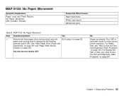
..." on page 301 and "Paper Path Service Checks" on page 161. Run T&D in automatic mode to step 2 on page 201. For Models 001, 002, or 003, see "How To Run the Test and Diagnostic (T&D) Programs" on page 301. Perform the main paper drive service check and the Go to verify correct... Paper Movement Symptom Explanation Paper Load and Feed Failures No Paper Movement 099 Condition Persists Suspected FRUs/Causes Paper feed motor Printer logic board Mechanical parts Table 8.
..." on page 301 and "Paper Path Service Checks" on page 161. Run T&D in automatic mode to step 2 on page 201. For Models 001, 002, or 003, see "How To Run the Test and Diagnostic (T&D) Programs" on page 301. Perform the main paper drive service check and the Go to verify correct... Paper Movement Symptom Explanation Paper Load and Feed Failures No Paper Movement 099 Condition Persists Suspected FRUs/Causes Paper feed motor Printer logic board Mechanical parts Table 8.

Maintenance Manual
Page 71
... 72. Are you here due to step 3 on page 197, and repeat the test at least 10 pages. Repair as needed. Models 001, 002, or 003, see "How To Print the Print Test" on page 160 and print at least 5 times (10 pages). If this is a Model A00, see "How To... the The ribbon is the customer's print test? Remove the ribbon (see "How To Run the Test and Diagnostic (T&D) Programs" on page 72. guide are part of the ribbon assembly. responsibility. Diagnosing Problems 71 Table 10. The ribbon lift bar, lift bracket, and ribbon Go to a '56', '73', '053', or '056...
... 72. Are you here due to step 3 on page 197, and repeat the test at least 10 pages. Repair as needed. Models 001, 002, or 003, see "How To Print the Print Test" on page 160 and print at least 5 times (10 pages). If this is a Model A00, see "How To... the The ribbon is the customer's print test? Remove the ribbon (see "How To Run the Test and Diagnostic (T&D) Programs" on page 72. guide are part of the ribbon assembly. responsibility. Diagnosing Problems 71 Table 10. The ribbon lift bar, lift bracket, and ribbon Go to a '56', '73', '053', or '056...

Maintenance Manual
Page 75
WARNING: Do not install a power supply with a different part number. Symptom Explanation Display blank and keys do not operate Power failure Suspected FRUs/Causes Power supply Power cord Logic board Operator panel Sensors Motors Attachment card Tractor assembly Stacker assembly ASF assembly Cables Chapter 1. MAP 0150: Power Supply Models A00, 001, and 002, use a low voltage or high voltage power supply depending on the country in which the printer is found. Diagnosing Problems 75 The Model 003 has a auto-ranging universal power supply.
WARNING: Do not install a power supply with a different part number. Symptom Explanation Display blank and keys do not operate Power failure Suspected FRUs/Causes Power supply Power cord Logic board Operator panel Sensors Motors Attachment card Tractor assembly Stacker assembly ASF assembly Cables Chapter 1. MAP 0150: Power Supply Models A00, 001, and 002, use a low voltage or high voltage power supply depending on the country in which the printer is found. Diagnosing Problems 75 The Model 003 has a auto-ranging universal power supply.
Maintenance Manual
Page 94
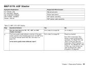
... Go to step 6 on page 161. No Go to a '02', '97', '087', or '099' display message? For Models 001, 002, or 003, see "How To Run the Test and Diagnostic (T&D) Programs" on page 96. 2. MAP 0170: ASF Stacker Symptom Explanation 02 FORMS JAM 97 STACKER ERROR 087... STACKER ERROR 099 FORMS JAMMED Stacker Failures Suspected FRUs/Causes Mechanical parts Printer logic board ASF stacker assembly ASF stacker cable assembly Table 13. Repair as needed. Run T&D in the open ? Diagnosing Problems 94 MAP ...
... Go to step 6 on page 161. No Go to a '02', '97', '087', or '099' display message? For Models 001, 002, or 003, see "How To Run the Test and Diagnostic (T&D) Programs" on page 96. 2. MAP 0170: ASF Stacker Symptom Explanation 02 FORMS JAM 97 STACKER ERROR 087... STACKER ERROR 099 FORMS JAMMED Stacker Failures Suspected FRUs/Causes Mechanical parts Printer logic board ASF stacker assembly ASF stacker cable assembly Table 13. Repair as needed. Run T&D in the open ? Diagnosing Problems 94 MAP ...
Maintenance Manual
Page 99
...To Run the Test and Ensure the ASF stacker assembly is closed) Model A00, see "Logic (T&D) Programs" on For Models 001, 002, or 003, page 378. Run T&D in automatic mode to verify correct printer operation. Table 14. Run T&D in automatic mode to v Top cover magnet (Located... near the operator panel. page 201. Board - Are the parts OK? MAP 0180: Top Cover Interlock (continued) Step Questions/Actions Yes No 2. stacker assembly when the cover is installed correctly. Inspect the following...
...To Run the Test and Ensure the ASF stacker assembly is closed) Model A00, see "Logic (T&D) Programs" on For Models 001, 002, or 003, page 378. Run T&D in automatic mode to verify correct printer operation. Table 14. Run T&D in automatic mode to v Top cover magnet (Located... near the operator panel. page 201. Board - Are the parts OK? MAP 0180: Top Cover Interlock (continued) Step Questions/Actions Yes No 2. stacker assembly when the cover is installed correctly. Inspect the following...
Maintenance Manual
Page 100
... near the left side of the See "Operator Panel" on Board - For Model A00, see "Logic Board - Model A00, see "How To Are the parts OK? For see "How To Run the Test and Models 001 and 002, see "Logic Diagnostic (T&D) Programs" on operator panel, when the cover is closed...(T&D) Programs" on page 161. Models 001 and 002" on page 201. For Models 001, 002, or 003, see "How To Run the Test and Diagnostic (T&D) Programs" on page 161. Diagnosing Problems 100 Inspect the following parts for wear, damage, or binds: Install a new operator panel. page 378. v Operator panel cable and ...
... near the left side of the See "Operator Panel" on Board - For Model A00, see "Logic Board - Model A00, see "How To Are the parts OK? For see "How To Run the Test and Models 001 and 002, see "Logic Diagnostic (T&D) Programs" on operator panel, when the cover is closed...(T&D) Programs" on page 161. Models 001 and 002" on page 201. For Models 001, 002, or 003, see "How To Run the Test and Diagnostic (T&D) Programs" on page 161. Diagnosing Problems 100 Inspect the following parts for wear, damage, or binds: Install a new operator panel. page 378. v Operator panel cable and ...
Maintenance Manual
Page 101
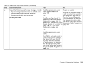
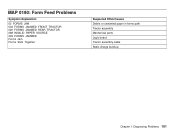
Diagnosing Problems 101 MAP 0190: Form Feed Problems Symptom Explanation 02 FORMS JAM 002 FORMS JAMMED FRONT TRACTOR 020 FORMS JAMMED REAR TRACTOR 088 INVALID PAPER SOURCE 099 FORMS JAMMED Forms Jam Forms Stick Together Suspected FRUs/Causes Debris or unwanted paper in forms path Tractor assembly Mechanical parts Logic board Tractor assembly cable Static charge build-up Chapter 1.
Diagnosing Problems 101 MAP 0190: Form Feed Problems Symptom Explanation 02 FORMS JAM 002 FORMS JAMMED FRONT TRACTOR 020 FORMS JAMMED REAR TRACTOR 088 INVALID PAPER SOURCE 099 FORMS JAMMED Forms Jam Forms Stick Together Suspected FRUs/Causes Debris or unwanted paper in forms path Tractor assembly Mechanical parts Logic board Tractor assembly cable Static charge build-up Chapter 1.
Maintenance Manual
Page 111
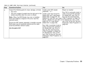
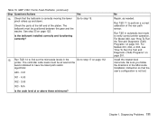
... Installation Instruction so that the bellcrank is not lost. Run T&D 11 to have the latest path switch algorithms: A00 - 3.01 001 - 4.00 002 - 3.00 003 - Table 15. For Model A00, see "How To Run the Test and Diagnostic (T&D) Programs" on page 161. For Models 001, 002, or... 003, see "How To Run the Test and Diagnostic (T&D) Programs" on page 201. Check the parts at the left end of the rear path sensor. Is the bellcrank installed correctly and functioning correctly? 15...
... Installation Instruction so that the bellcrank is not lost. Run T&D 11 to have the latest path switch algorithms: A00 - 3.01 001 - 4.00 002 - 3.00 003 - Table 15. For Model A00, see "How To Run the Test and Diagnostic (T&D) Programs" on page 161. For Models 001, 002, or... 003, see "How To Run the Test and Diagnostic (T&D) Programs" on page 201. Check the parts at the left end of the rear path sensor. Is the bellcrank installed correctly and functioning correctly? 15...
Maintenance Manual
Page 114
... attached with 2 screws, remove the platen to remove the plastic shield, and inspect it . No Repair, as needed. For Models 001, 002, or 003, see "How To Run the Test and Diagnostic (T&D) Programs" on page 201. Ensure that the shields are firmly attached. Note: If you suspect lower... plastic shield damage, determine which version part is not attached with 2 screws, remove the screws to inspect it for damage. For Model A00, see "How To Run the Test and Diagnostic ...
... attached with 2 screws, remove the platen to remove the plastic shield, and inspect it . No Repair, as needed. For Models 001, 002, or 003, see "How To Run the Test and Diagnostic (T&D) Programs" on page 201. Ensure that the shields are firmly attached. Note: If you suspect lower... plastic shield damage, determine which version part is not attached with 2 screws, remove the screws to inspect it for damage. For Model A00, see "How To Run the Test and Diagnostic ...
Maintenance Manual
Page 122
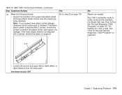
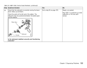
Check the parts at the left end of the rear path sensor. Run T&D 11 to step 34 on page 123. Chapter 1. Table 15. Yes Go to perform a correct calibration of the platen. e90aas4 Washer Bellcrank Is the bellcrank installed correctly and functioning correctly? Diagnosing Problems 122 Platen Gear No Repair, as needed. Check that the bellcrank is correctly moving the lower pinch rollers up and down. The bellcrank must be positioned between the platen gear and the washer. MAP 0190: Forms Feed Problems (continued) Step Questions/Actions 33.
Check the parts at the left end of the rear path sensor. Run T&D 11 to step 34 on page 123. Chapter 1. Table 15. Yes Go to perform a correct calibration of the platen. e90aas4 Washer Bellcrank Is the bellcrank installed correctly and functioning correctly? Diagnosing Problems 122 Platen Gear No Repair, as needed. Check that the bellcrank is correctly moving the lower pinch rollers up and down. The bellcrank must be positioned between the platen gear and the washer. MAP 0190: Forms Feed Problems (continued) Step Questions/Actions 33.