
Maintenance Manual
Page 7
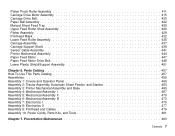
Preventative Maintenance 483 Contents 7 Platen Pinch Roller Assembly 411 Carriage Drive Motor Assembly 415 Carriage Drive Belt 420 Paper Bail Assembly 422 Manual Sheet Feed Tray 425 Upper Feed Roller Shaft Assembly 426 Platen Assembly 429 Printhead Mask 432 Lower Feed Roller Assembly 435 Carriage Assembly 437 Carriage ...
Preventative Maintenance 483 Contents 7 Platen Pinch Roller Assembly 411 Carriage Drive Motor Assembly 415 Carriage Drive Belt 420 Paper Bail Assembly 422 Manual Sheet Feed Tray 425 Upper Feed Roller Shaft Assembly 426 Platen Assembly 429 Printhead Mask 432 Lower Feed Roller Assembly 435 Carriage Assembly 437 Carriage ...

Maintenance Manual
Page 18
... the programming functions that control the printer. This guide describes the operating procedures for IBM Customer Engineers, S229-8124. v AXIS 5400 User's Manual. This reference is also applicable to the Model 003: v IBM 4247 Printer Model 003 User's Guide, S544-5780. This reference is not shipped with Models 001 and 002 of the Models 001 and...
... the programming functions that control the printer. This guide describes the operating procedures for IBM Customer Engineers, S229-8124. v AXIS 5400 User's Manual. This reference is also applicable to the Model 003: v IBM 4247 Printer Model 003 User's Guide, S544-5780. This reference is not shipped with Models 001 and 002 of the Models 001 and...

Maintenance Manual
Page 19
... 001, but it is different in the Model 003 This Maintenance Information Manual is changing to or from 100 V to quickly change between hardware configurations without any input voltage from a coax configuration, or when upgrading for the IBM 4247 Printer, Models A00, 001, 002, and the new 003. this includes serial, twinax, coax, and Ethernet...
... 001, but it is different in the Model 003 This Maintenance Information Manual is changing to or from 100 V to quickly change between hardware configurations without any input voltage from a coax configuration, or when upgrading for the IBM 4247 Printer, Models A00, 001, 002, and the new 003. this includes serial, twinax, coax, and Ethernet...

Maintenance Manual
Page 45
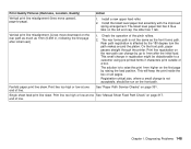
...Power off (O) the printer. 2) Load the printer with at least 22 inches (55.9 cm) of blank letter or legal size paper in the manual sheet feed to make the printer Not Ready (only the Power LED is lighted). 5) Press the Test key. Ensure the host system and program ... cable length restrictions are no blank fanfold forms available, install two sheets of blank, fanfold forms in the IBM 4247 Printer Models 001, 002 User's Guide, SA24-4408 or IBM 4247 Printer Model 003 User's Guide, S544-5780 for the configuration to verify correct printer still fails, continue with the most probable...
...Power off (O) the printer. 2) Load the printer with at least 22 inches (55.9 cm) of blank letter or legal size paper in the manual sheet feed to make the printer Not Ready (only the Power LED is lighted). 5) Press the Test key. Ensure the host system and program ... cable length restrictions are no blank fanfold forms available, install two sheets of blank, fanfold forms in the IBM 4247 Printer Models 001, 002 User's Guide, SA24-4408 or IBM 4247 Printer Model 003 User's Guide, S544-5780 for the configuration to verify correct printer still fails, continue with the most probable...
Maintenance Manual
Page 94
... metal deflector must be in Automatic Test Mode to step 3 on page 95. (down) position when feeding paper from the ASF bins or from the manual sheet feed tray. No Go to step 6 on page 161. Diagnosing Problems 94 See step 3 on page 201. Repair as needed. For Models 001, 002..., or 003, see "How To Run the Test and Diagnostic (T&D) Programs" on page 96. 2. Go to step 2. For Model A00, see "How To Run the Test and...
... metal deflector must be in Automatic Test Mode to step 3 on page 95. (down) position when feeding paper from the ASF bins or from the manual sheet feed tray. No Go to step 6 on page 161. Diagnosing Problems 94 See step 3 on page 201. Repair as needed. For Models 001, 002..., or 003, see "How To Run the Test and Diagnostic (T&D) Programs" on page 96. 2. Go to step 2. For Model A00, see "How To Run the Test and...
Maintenance Manual
Page 95
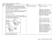
... mm Between Vane and Pin 2 to guide the paper into the stacker. Install a new logic board. or - Feed forms alternately from the ASF or the manual sheet feed tray and observe the stacker vane. or - Install a new stacker cable. For Models 001, 002, or... 003, see "Logic Board Model A00" on page 201. When ASF or manual sheet feed configurations are used , the stacker vane will be in the up position to allow the paper to verify correct printer...
... mm Between Vane and Pin 2 to guide the paper into the stacker. Install a new logic board. or - Feed forms alternately from the ASF or the manual sheet feed tray and observe the stacker vane. or - Install a new stacker cable. For Models 001, 002, or... 003, see "Logic Board Model A00" on page 201. When ASF or manual sheet feed configurations are used , the stacker vane will be in the up position to allow the paper to verify correct printer...
Maintenance Manual
Page 142
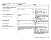
...4. See "MAP 0180: Top Cover Interlock" on page 94. 088 INVALID PAPER SOURCE USE MANUAL OR CHANGE CONFIGURATION Printer requires a paper source not installed. 1. Power off and on the ... that an ASF 1. Diagnosing Problems 142 Error Messages for Models 001, 002, and 003 (continued) Message Description Action 070 PRINTER BOARD CHANGED VERIFY CONFIGURATION SETTINGS Occurs when printer logic... after completing your service procedures by performing this procedure. If message remains, see IBM 4247 Printer Models 001, 002 User's Guide, SA24-4408). 2. Verify printer configuration ...
...4. See "MAP 0180: Top Cover Interlock" on page 94. 088 INVALID PAPER SOURCE USE MANUAL OR CHANGE CONFIGURATION Printer requires a paper source not installed. 1. Power off and on the ... that an ASF 1. Diagnosing Problems 142 Error Messages for Models 001, 002, and 003 (continued) Message Description Action 070 PRINTER BOARD CHANGED VERIFY CONFIGURATION SETTINGS Occurs when printer logic... after completing your service procedures by performing this procedure. If message remains, see IBM 4247 Printer Models 001, 002 User's Guide, SA24-4408). 2. Verify printer configuration ...

Maintenance Manual
Page 143
... paper still present 1. The coax attachment card is not compatible Printer base code must be reloaded for pieces of the Model 003, or change the attachment card to load forms into a manual sheet feed, under the platen, fanfold path. Path sensor detected forms already 3. Chapter 1. the tractor pins, with the printer base...
... paper still present 1. The coax attachment card is not compatible Printer base code must be reloaded for pieces of the Model 003, or change the attachment card to load forms into a manual sheet feed, under the platen, fanfold path. Path sensor detected forms already 3. Chapter 1. the tractor pins, with the printer base...
Maintenance Manual
Page 148
... pages. the older has 1 tab. This will keep the print inside the box on page 301. Print line too high or low at one See "Manual Sheet Feed Path Check" on the rear path as much as the front forms path. Install a new upper feed roller. 2. Chapter 1.
... pages. the older has 1 tab. This will keep the print inside the box on page 301. Print line too high or low at one See "Manual Sheet Feed Path Check" on the rear path as much as the front forms path. Install a new upper feed roller. 2. Chapter 1.

Maintenance Manual
Page 150
... page 101. See "MAP 0190: Form Feed Problems" on page 70. Description of adjusting AFTA wheel vary on same paper-weight. Fanfold paper jams. Manual sheet feed jams. ASF feed jams. Fanfold paper print line skew. See "MAP 0110: Automatic Sheet Feeder" on page 62. Results of Failure Buzzer ...sounds continuously. Manual sheet feed paper does not load or feed. See "MAP 0130: No Paper Movement" on page 26. Model 003" on page 70. Print line too high or low on one end of line. See "MAP...
... page 101. See "MAP 0190: Form Feed Problems" on page 70. Description of adjusting AFTA wheel vary on same paper-weight. Fanfold paper jams. Manual sheet feed jams. ASF feed jams. Fanfold paper print line skew. See "MAP 0110: Automatic Sheet Feeder" on page 62. Results of Failure Buzzer ...sounds continuously. Manual sheet feed paper does not load or feed. See "MAP 0130: No Paper Movement" on page 26. Model 003" on page 70. Print line too high or low on one end of line. See "MAP...
Maintenance Manual
Page 152
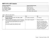
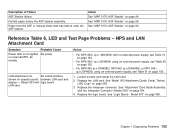
... board LAN card Action v For NPS 540+ (p.n. 30H4054) with the Interposer Connector (Model 003)" on external NPS- Replace the interposer connector. Description of Failure ASF Stacker failure. Paper from the ASF or manual sheet feed tray fails to enter the ASF stacker. Action See "MAP 0170: ASF Stacker"... on page 366. Replace the LAN card. Model 003" on page 94. See "Logic Board - NPS and LAN Attachment Card...
... board LAN card Action v For NPS 540+ (p.n. 30H4054) with the Interposer Connector (Model 003)" on external NPS- Replace the interposer connector. Description of Failure ASF Stacker failure. Paper from the ASF or manual sheet feed tray fails to enter the ASF stacker. Action See "MAP 0170: ASF Stacker"... on page 366. Replace the LAN card. Model 003" on page 94. See "Logic Board - NPS and LAN Attachment Card...
Maintenance Manual
Page 158
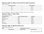
... Cable Connectors Table 24. Reference Table 11, Paper Paths Table 25. Guide and bail positions Selected Paper Path Forms Guide Metal Deflector Front Push Open Manual Sheet Feed Open Rear Push Open ASF Open Rear Pull Closed Front Push-Pull Closed Paper Bail Closed Closed Closed Closed Removed Closed Reference Table...
... Cable Connectors Table 24. Reference Table 11, Paper Paths Table 25. Guide and bail positions Selected Paper Path Forms Guide Metal Deflector Front Push Open Manual Sheet Feed Open Rear Push Open ASF Open Rear Pull Closed Front Push-Pull Closed Paper Bail Closed Closed Closed Closed Removed Closed Reference Table...
Maintenance Manual
Page 166
... number. The test completed successfully if the display advances to repeat T&D05 6. Chapter 2. If the loop-back connector is displayed. 7. T&D07 - Online Auto Sheet Feed Manual Sheet Feed Front Push Rear Pull Path 6 Quiet 5 Rear Push Tear Park 12 11 Micro 4 Micro 3 Font Pitch 10 9 Load/ Form Feed 2 Line Feed 8 Online...
... number. The test completed successfully if the display advances to repeat T&D05 6. Chapter 2. If the loop-back connector is displayed. 7. T&D07 - Online Auto Sheet Feed Manual Sheet Feed Front Push Rear Pull Path 6 Quiet 5 Rear Push Tear Park 12 11 Micro 4 Micro 3 Font Pitch 10 9 Load/ Form Feed 2 Line Feed 8 Online...
Maintenance Manual
Page 173
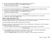
Load a single-sheet of paper into the front tractor (FF) or manual sheet feed tray (SS). 3. Press the Load/Form key to AFTA=0. 2. YES NO Verifying AFTA Calibration Using T&D12: To verify the calibration: 1. Chapter 2. Return here ...
Load a single-sheet of paper into the front tractor (FF) or manual sheet feed tray (SS). 3. Press the Load/Form key to AFTA=0. 2. YES NO Verifying AFTA Calibration Using T&D12: To verify the calibration: 1. Chapter 2. Return here ...
Maintenance Manual
Page 184
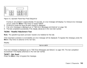
... here after the sensors are tuned. If an error message is complete, the display advances to "T&D Error Messages and Actions" on the manual sheet feed tray. 2. 19. The test completed successfully if the display advances to the next test number. - For printout analysis, see...to the next test number. If the following messages appear in .) wide] on page 190. 5. When the print test is displayed, go to check manual sheet paper feed and line skew. These 2 messages display sequentially: T&D 18 USER INSERT CUT SHEET 1. Diagnostics 184 If an error message is CLOSE or...
... here after the sensors are tuned. If an error message is complete, the display advances to "T&D Error Messages and Actions" on the manual sheet feed tray. 2. 19. The test completed successfully if the display advances to the next test number. - For printout analysis, see...to the next test number. If the following messages appear in .) wide] on page 190. 5. When the print test is displayed, go to check manual sheet paper feed and line skew. These 2 messages display sequentially: T&D 18 USER INSERT CUT SHEET 1. Diagnostics 184 If an error message is CLOSE or...
Maintenance Manual
Page 186
... Micro ↑ key to verify correct sensor operation. The following , giving you the option of the front fanfold presence sensor, rear fanfold presence sensor, and manual cutsheet presence sensor. Use this mode press the Micro ↑ key, and go to step 10 on page 189. 3. Chapter 2. To select this test to...
... Micro ↑ key to verify correct sensor operation. The following , giving you the option of the front fanfold presence sensor, rear fanfold presence sensor, and manual cutsheet presence sensor. Use this mode press the Micro ↑ key, and go to step 10 on page 189. 3. Chapter 2. To select this test to...
Maintenance Manual
Page 188
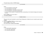
... to skip to enter. The following displays: Y SENSOR LEVEL N This part of 20 mV. The current sensor measurements display: C:x1 F:x2 R:x3 where: v x1 is manual path measurement v x2 is front path measurement v x3 is intended for rear path and rollers open v x1, x2, x3, x4 are numbers in NVRAM display...: Cx1 Fx2 Rx3(x4) where: v x1 is the threshold for manual path v x2 is the threshold for front path v x3 is the threshold for rear path and rollers closed v x4 is the threshold for use by...
... to skip to enter. The following displays: Y SENSOR LEVEL N This part of 20 mV. The current sensor measurements display: C:x1 F:x2 R:x3 where: v x1 is manual path measurement v x2 is front path measurement v x3 is intended for rear path and rollers open v x1, x2, x3, x4 are numbers in NVRAM display...: Cx1 Fx2 Rx3(x4) where: v x1 is the threshold for manual path v x2 is the threshold for front path v x3 is the threshold for rear path and rollers closed v x4 is the threshold for use by...
Maintenance Manual
Page 197
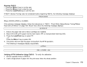
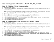
...at least 22 in. (55.9 cm) of blank, fanfold forms in the same tractor and forms path the customer is using . The message '4247 OPERATOR TESTS' appears. 6. Power off (O) the printer. 2. Use the manual sheet feed to finish. 8. Press the Micro ↓ key until the 'Printer Demonstration' test is displayed below... the printer Not Ready (only the Power LED is lighted). 5. Press the Cancel Print key to exit test mode. Models 001, 002, and 003 How To Print the Printer Demonstration 1. Press the Stop key to make the printer Not Ready (only the Power LED is lighted). 5.
...at least 22 in. (55.9 cm) of blank, fanfold forms in the same tractor and forms path the customer is using . The message '4247 OPERATOR TESTS' appears. 6. Power off (O) the printer. 2. Use the manual sheet feed to finish. 8. Press the Micro ↓ key until the 'Printer Demonstration' test is displayed below... the printer Not Ready (only the Power LED is lighted). 5. Press the Cancel Print key to exit test mode. Models 001, 002, and 003 How To Print the Printer Demonstration 1. Press the Stop key to make the printer Not Ready (only the Power LED is lighted). 5.

Maintenance Manual
Page 198
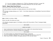
...To print a custom set on the Model 003 and later Models of the 001 and 002: a. b. Stated another way, only the 8 most current errors are encountered, the unused entries remain at least 22 in the same tractor the customer is using. The message '4247 OPERATOR TESTS' appears, and the Online ...store up to print. The current printer configuration is shown on the display is displayed below '4247 OPERATOR TESTS'. 5. Load the printer with at zero. Note: If there are lighted). 3. Use the manual sheet feed to exit test mode. Press the Stop key to print each of 8 Code Description...
...To print a custom set on the Model 003 and later Models of the 001 and 002: a. b. Stated another way, only the 8 most current errors are encountered, the unused entries remain at least 22 in the same tractor the customer is using. The message '4247 OPERATOR TESTS' appears, and the Online ...store up to print. The current printer configuration is shown on the display is displayed below '4247 OPERATOR TESTS'. 5. Load the printer with at zero. Note: If there are lighted). 3. Use the manual sheet feed to exit test mode. Press the Stop key to print each of 8 Code Description...

Maintenance Manual
Page 199
... the error log or usage metrics. 2. Diagnostics 199 Do not press the Stop key. v At the 'YES' display, press the Enter key. Use the manual sheet feed to 'Print Error Log', 'Clear Error Log', or 'Print Usage Metrics.' v At the 'Clear Error Log' display, press the Enter key. ...for the following data: v Power-on hours v Power-on line two. 9. NOT READY' appears. 7. To exit test mode: Chapter 2. Press the Menu key. 8. '4247 OPERATOR TESTS' is displayed on line one and a test name on cycles v DP, DP text, and NLQ characters v Number (quantity) of barcodes v Number (quantity) of...
... the error log or usage metrics. 2. Diagnostics 199 Do not press the Stop key. v At the 'YES' display, press the Enter key. Use the manual sheet feed to 'Print Error Log', 'Clear Error Log', or 'Print Usage Metrics.' v At the 'Clear Error Log' display, press the Enter key. ...for the following data: v Power-on hours v Power-on line two. 9. NOT READY' appears. 7. To exit test mode: Chapter 2. Press the Menu key. 8. '4247 OPERATOR TESTS' is displayed on line one and a test name on cycles v DP, DP text, and NLQ characters v Number (quantity) of barcodes v Number (quantity) of...
