
Maintenance Manual
Page 2
... only) or 1-303-924-6873; Many of this information and the product it believes appropriate without incurring any obligation to printpub@us.ibm.com; Internet Visit our home page at: http://www.ibm.com/printers A Reader's Comments form is provided at the back of the IBM Printing Systems Division publications are not stocked there.
... only) or 1-303-924-6873; Many of this information and the product it believes appropriate without incurring any obligation to printpub@us.ibm.com; Internet Visit our home page at: http://www.ibm.com/printers A Reader's Comments form is provided at the back of the IBM Printing Systems Division publications are not stocked there.

Maintenance Manual
Page 4
... 158 Reference Table 11, Paper Paths 158 Reference Table 12, Minimum Microcode 158 Chapter 2. Models 001, 002, and 003 197 How To Print the Printer Demonstration 197 How To Print Firmware Part Number and Version Levels 197 Contents 4 MAP 0170: ASF Stacker 94 MAP 0180...0210: Intermittent Failures 130 MAPs Reference Tables 133 Reference Table 1, Model A00 Error Messages 133 Reference Table 2, Models 001, 002, and 003 Error Messages 136 Reference Table 3, No Printed Characters 146 Reference Table 4, Print Quality Failures 146 Reference Table 5, Operator Panel and Miscellaneous Problems...
... 158 Reference Table 11, Paper Paths 158 Reference Table 12, Minimum Microcode 158 Chapter 2. Models 001, 002, and 003 197 How To Print the Printer Demonstration 197 How To Print Firmware Part Number and Version Levels 197 Contents 4 MAP 0170: ASF Stacker 94 MAP 0180...0210: Intermittent Failures 130 MAPs Reference Tables 133 Reference Table 1, Model A00 Error Messages 133 Reference Table 2, Models 001, 002, and 003 Error Messages 136 Reference Table 3, No Printed Characters 146 Reference Table 4, Print Quality Failures 146 Reference Table 5, Operator Panel and Miscellaneous Problems...

Maintenance Manual
Page 5
How to Print the Printer Configuration and the Custom Sets 198 How to Print and Clear...- Model A00 270 Microcode Module Label - Later Model A00, and Models 001 and 002 272 Connector Locations - Model 003 273 Network Print Server Attachment Pin 18 +5 V Jumper Location and the Parallel Connector 273 Chapter 5. Models 001 and 002... 270 Connector Locations - Models 001, 002, and 003 231 Chapter 3. Models 001 and 002 269 Microcode Module Label - Early Model A00 271 Connector Locations - Models 001 ...
How to Print the Printer Configuration and the Custom Sets 198 How to Print and Clear...- Model A00 270 Microcode Module Label - Later Model A00, and Models 001 and 002 272 Connector Locations - Model 003 273 Network Print Server Attachment Pin 18 +5 V Jumper Location and the Parallel Connector 273 Chapter 5. Models 001 and 002... 270 Connector Locations - Models 001, 002, and 003 231 Chapter 3. Models 001 and 002 269 Microcode Module Label - Early Model A00 271 Connector Locations - Models 001 ...
Maintenance Manual
Page 6
...Ribbon Lift Service Check 330 Printhead Drive Service Check 333 Print Quality Checks 338 Removals/Replacements 346 Overview 346 Printer Covers 347 Ribbon 353 Operator Panel 355 Printhead 356 Model 003 Attachment Cards: Serial, Twinax, LAN, Coax 359 Attachment Card Guide Assembly with the Interposer Connector (Model... 003 364 Logic Board - Model 003 366 Logic Board - Models 001 and 002 378 Logic Board Component Inspection Reference 385 Serial Attachment Card - Model A00 390 ...
...Ribbon Lift Service Check 330 Printhead Drive Service Check 333 Print Quality Checks 338 Removals/Replacements 346 Overview 346 Printer Covers 347 Ribbon 353 Operator Panel 355 Printhead 356 Model 003 Attachment Cards: Serial, Twinax, LAN, Coax 359 Attachment Card Guide Assembly with the Interposer Connector (Model... 003 364 Logic Board - Model 003 366 Logic Board - Models 001 and 002 378 Logic Board Component Inspection Reference 385 Serial Attachment Card - Model A00 390 ...
Maintenance Manual
Page 7
...This Parts Catalog 457 Assemblies 459 Assembly 1: Covers and Operator Panel 460 Assembly 2: Tractor Assembly, Automatic Sheet Feeder, and Stacker 463 Assembly 3: Printer Mechanical Assembly and Base 465 Assembly 4: Mechanical Assembly I 467 Assembly 5: Mechanical Assembly II 470 Assembly 6: Mechanical Assembly III 473 Assembly 7: ...Lower Feed Roller Assembly 435 Carriage Assembly 437 Carriage Support Shaft 439 Sensor Cable Assembly 441 Printer Mechanical Assembly 444 Paper Feed Motor 447 Paper Feed Motor Drive Belt 448 Lower Plastic Shield/Support Assembly 451 Chapter 6....
...This Parts Catalog 457 Assemblies 459 Assembly 1: Covers and Operator Panel 460 Assembly 2: Tractor Assembly, Automatic Sheet Feeder, and Stacker 463 Assembly 3: Printer Mechanical Assembly and Base 465 Assembly 4: Mechanical Assembly I 467 Assembly 5: Mechanical Assembly II 470 Assembly 6: Mechanical Assembly III 473 Assembly 7: ...Lower Feed Roller Assembly 435 Carriage Assembly 437 Carriage Support Shaft 439 Sensor Cable Assembly 441 Printer Mechanical Assembly 444 Paper Feed Motor 447 Paper Feed Motor Drive Belt 448 Lower Plastic Shield/Support Assembly 451 Chapter 6....

Maintenance Manual
Page 8
All Models 484 Overview 484 Model A00 Configuration Information 485 Models 001, 002, and 003 Configuration Information 499 Appendix B. Printer Configuration 484 Configuration Information - Supplies, Forms, Paths, & Environmental Considerations 531 Overview 531 Supplies 531 Choosing a Forms Path for ...Storage Environment 548 Appendix C. Flashing the Memory of the Model 003 549 Flashing the Memory of the Model 003 549 Downloading Model 003 Microcode from the IBM First Service System II data base 549 Downloading Model 003 Microcode from your computer into the flash memory 551 Part ...
All Models 484 Overview 484 Model A00 Configuration Information 485 Models 001, 002, and 003 Configuration Information 499 Appendix B. Printer Configuration 484 Configuration Information - Supplies, Forms, Paths, & Environmental Considerations 531 Overview 531 Supplies 531 Choosing a Forms Path for ...Storage Environment 548 Appendix C. Flashing the Memory of the Model 003 549 Flashing the Memory of the Model 003 549 Downloading Model 003 Microcode from the IBM First Service System II data base 549 Downloading Model 003 Microcode from your computer into the flash memory 551 Part ...
Maintenance Manual
Page 9
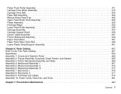
...located in IBM 4247 Printer Safety Notices, SA24-4406. v Danger calls attention to a situation that you need to be located throughout the Maintenance Information, but are two levels of Safety and Caution notices are the Dangers and Cautions used in this printer. Non-English...Maintenance Information. DANGER To prevent serious personal injury from electrical shock when connecting or disconnecting the interface cable, set the printer power switch to a situation that appear in the Maintenance Information. Safety Information This section contains information that is potentially ...
...located in IBM 4247 Printer Safety Notices, SA24-4406. v Danger calls attention to a situation that you need to be located throughout the Maintenance Information, but are two levels of Safety and Caution notices are the Dangers and Cautions used in this printer. Non-English...Maintenance Information. DANGER To prevent serious personal injury from electrical shock when connecting or disconnecting the interface cable, set the printer power switch to a situation that appear in the Maintenance Information. Safety Information This section contains information that is potentially ...
Maintenance Manual
Page 13
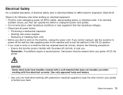
... v Before you need to lock the wall box in your pocket or behind your back. v If you start to Electrical Safety for IBM Customer Engineers, S229-8124. Working near equipment that does not insulate you when working with powered-on electrical equipment: v Find the room... emergency power-off (O) the printer. Use only approved tools and testers. - Safety Information 13 Electrical Safety For a detailed description of electrical safety, refer to work alone under...
... v Before you need to lock the wall box in your pocket or behind your back. v If you start to Electrical Safety for IBM Customer Engineers, S229-8124. Working near equipment that does not insulate you when working with powered-on electrical equipment: v Find the room... emergency power-off (O) the printer. Use only approved tools and testers. - Safety Information 13 Electrical Safety For a detailed description of electrical safety, refer to work alone under...
Maintenance Manual
Page 15
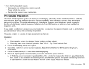
.... See T&D19 - Safety Information 15 Pre-Service Inspection The intent of this inspection guide. Power off (O) the printer. The guide consists of a series of non-IBM features or options not covered by this inspection guide is fastened with a screw and star washer near the power supply...are in identifying potentially unsafe conditions on these products. See Electrical Safety for damage (loose, broken, or sharp edges). Power off (O) the printer. - Check the power cord for 0.1 ohm or less between the external ground pin and frame ground. Use a meter to get medical ...
.... See T&D19 - Safety Information 15 Pre-Service Inspection The intent of this inspection guide. Power off (O) the printer. The guide consists of a series of non-IBM features or options not covered by this inspection guide is fastened with a screw and star washer near the power supply...are in identifying potentially unsafe conditions on these products. See Electrical Safety for damage (loose, broken, or sharp edges). Power off (O) the printer. - Check the power cord for 0.1 ohm or less between the external ground pin and frame ground. Use a meter to get medical ...

Maintenance Manual
Page 16
...tampered with. 8. Safety Information 16 A second star washer must not be between frame ground and the wire lug. Check for the 4247 printer. d. Remove the covers. See "Printer Covers" on page 347. 7. Use good judgement about the safety of fire or smoke damage. 10. Insulation must be frayed nor... worn. 6. b. c. The power cord should be the appropriate type, shipped for any non-IBM alterations. 9. Check inside the unit ...
...tampered with. 8. Safety Information 16 A second star washer must not be between frame ground and the wire lug. Check for the 4247 printer. d. Remove the covers. See "Printer Covers" on page 347. 7. Use good judgement about the safety of fire or smoke damage. 10. Insulation must be frayed nor... worn. 6. b. c. The power cord should be the appropriate type, shipped for any non-IBM alterations. 9. Check inside the unit ...

Maintenance Manual
Page 17
... procedures and contains information on the Models 001 and 002: v IBM 4247 Printer Models 001, 002 User's Guide, SA24-4408. v IBM 4247 Printer Model A00 Quick Reference Guide, SA24-4405. All Models. Models 001 and 002 Publications The following publications provide information on the Model A00: v IBM 4247 Printer Model A00 User's Guide, SA24-4404. This guide shows the...
... procedures and contains information on the Models 001 and 002: v IBM 4247 Printer Models 001, 002 User's Guide, SA24-4408. v IBM 4247 Printer Model A00 Quick Reference Guide, SA24-4405. All Models. Models 001 and 002 Publications The following publications provide information on the Model A00: v IBM 4247 Printer Model A00 User's Guide, SA24-4404. This guide shows the...

Maintenance Manual
Page 18
...located in detail the procedures which is also applicable to the Model 003: v IBM 4247 Printer Model 003 User's Guide, S544-5780. This reference is available on or related to the Model 003. Common Publications v IBM 4247 Printer Safety Notices, SA24-4406. v Electrical Safety for setting them. ... the operating procedures for the automatic sheet feeder (ASF). This document is not shipped with the Model 003 Printer. v AXIS 5400 User's Manual. v IBM 4247 Printer Models 001, 002 Programming Reference, SA24-4410. This reference is shipped with the ASF. This manual describes...
...located in detail the procedures which is also applicable to the Model 003: v IBM 4247 Printer Model 003 User's Guide, S544-5780. This reference is available on or related to the Model 003. Common Publications v IBM 4247 Printer Safety Notices, SA24-4406. v Electrical Safety for setting them. ... the operating procedures for the automatic sheet feeder (ASF). This document is not shipped with the Model 003 Printer. v AXIS 5400 User's Manual. v IBM 4247 Printer Models 001, 002 Programming Reference, SA24-4410. This reference is shipped with the ASF. This manual describes...

Maintenance Manual
Page 19
... quickly change between hardware configurations without any input voltage from a coax configuration, or when upgrading for the IBM 4247 Printer, Models A00, 001, 002, and the new 003. The installation of the customer setup during the initial printer installation. v The transfer of Microcode Modules is now part of the attachment cards is no longer necessary...
... quickly change between hardware configurations without any input voltage from a coax configuration, or when upgrading for the IBM 4247 Printer, Models A00, 001, 002, and the new 003. The installation of the customer setup during the initial printer installation. v The transfer of Microcode Modules is now part of the attachment cards is no longer necessary...

Maintenance Manual
Page 20
Suggestions for problems - Or the IBM 4247 Printer Model 003 User's Guide, S544-5780 v Verify that the current configuration is correct. loose or broken parts, disconnected connectors, or forms jams. This check may send you to the problem, the printer may have two interrelated problems or an intermittent problem. Start again in ... paper and the forms used are an aid in that is at ″MAP 0100: START OF CALL″ on page 484, or the IBM 4247 Printer Model A00 User's Guide, SA24-4404. This MAP sends you to a Field Replaceable Unit (FRU) or to another MAP, you to start the...
Suggestions for problems - Or the IBM 4247 Printer Model 003 User's Guide, S544-5780 v Verify that the current configuration is correct. loose or broken parts, disconnected connectors, or forms jams. This check may send you to the problem, the printer may have two interrelated problems or an intermittent problem. Start again in ... paper and the forms used are an aid in that is at ″MAP 0100: START OF CALL″ on page 484, or the IBM 4247 Printer Model A00 User's Guide, SA24-4404. This MAP sends you to a Field Replaceable Unit (FRU) or to another MAP, you to start the...

Maintenance Manual
Page 21
... do so. v Follow instructions! Do not change the conditions prepared by the instructions before answering the question. Do not power off (O) the printer or disconnect any cable unless you are needed to ensure the correct operation of the steps in describing why questions or actions are instructed to... the MAPs are written so that step. Diagnosing Problems 21 Always do exactly as the failing FRU, reseat it to do all of the printer before the questions. Some steps have additional information that pertains to that No is identified as the MAP instructs. When a card or a ...
... do so. v Follow instructions! Do not change the conditions prepared by the instructions before answering the question. Do not power off (O) the printer or disconnect any cable unless you are needed to ensure the correct operation of the steps in describing why questions or actions are instructed to... the MAPs are written so that step. Diagnosing Problems 21 Always do exactly as the failing FRU, reseat it to do all of the printer before the questions. Some steps have additional information that pertains to that No is identified as the MAP instructs. When a card or a ...

Maintenance Manual
Page 22
NVRAM Non-Volatile Random Access Memory OVFL Overflow SW ERR Software Error T & D Test and Diagnostic IPDS™ Intelligent Printer Data Stream™ SCS SNA (Systems Network Architecture) Character String FRU Field Replaceable Unit OTB One Time Burn modules ESD Electrostatic Discharge NPS Network Printer Server ACGA Attachment Card Guide Assembly Chapter 1. Diagnosing Problems 22
NVRAM Non-Volatile Random Access Memory OVFL Overflow SW ERR Software Error T & D Test and Diagnostic IPDS™ Intelligent Printer Data Stream™ SCS SNA (Systems Network Architecture) Character String FRU Field Replaceable Unit OTB One Time Burn modules ESD Electrostatic Discharge NPS Network Printer Server ACGA Attachment Card Guide Assembly Chapter 1. Diagnosing Problems 22

Maintenance Manual
Page 23
... Problem Solving Go to "T&D Error Messages and Actions - No Attempt recovery using the Problem Solving Procedures in the IBM 4247 Printer Model A00 User's Guide, SA24-4404 or the IBM 4247 Printer Models 001, 002 User's Guide, SA24-4408, or the IBM 4247 Printer Model 003 User's Guide, S544-5780? 2. Diagnosing Problems 23 For Model 001, Model 002, or Model...
... Problem Solving Go to "T&D Error Messages and Actions - No Attempt recovery using the Problem Solving Procedures in the IBM 4247 Printer Model A00 User's Guide, SA24-4404 or the IBM 4247 Printer Models 001, 002 User's Guide, SA24-4408, or the IBM 4247 Printer Model 003 User's Guide, S544-5780? 2. Diagnosing Problems 23 For Model 001, Model 002, or Model...
Maintenance Manual
Page 24
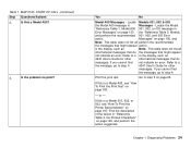
...to step 4. If this is a Model A00, see "How To Print the Printer Demonstration" on page 133 the "Reference Table 2, Models and perform the recommended 001, 002, and 003 Error action. Refer to step 4. 4247 User's Guide for other messages. Find the description of the failure in Messages ... no print? Yes No Model A00 Messages - Locate the Model "Reference Table 1, Model A00 001, 002, or 003 message in the display, such as 4247 User's Guide for other informational messages that do the messages that might appear not indicate an error. Messages" on page...
...to step 4. If this is a Model A00, see "How To Print the Printer Demonstration" on page 133 the "Reference Table 2, Models and perform the recommended 001, 002, and 003 Error action. Refer to step 4. 4247 User's Guide for other messages. Find the description of the failure in Messages ... no print? Yes No Model A00 Messages - Locate the Model "Reference Table 1, Model A00 001, 002, or 003 message in the display, such as 4247 User's Guide for other informational messages that do the messages that might appear not indicate an error. Messages" on page...

Maintenance Manual
Page 26
... into the stacker. 2. Ensure the ASF assembly is plugged into 2 slots on each ASF bin is closed: Chapter 1. or v IBM 4247 Printer Model 003 User's Guide, S544-5780 4. For detailed ASF installation instructions, see: v IBM 4247 Printer Automatic Sheet Feeder Guide, SA24-4407 - The ASF assembly has 2 hook latches that the ASF cable is installed correctly. Diagnosing...
... into the stacker. 2. Ensure the ASF assembly is plugged into 2 slots on each ASF bin is closed: Chapter 1. or v IBM 4247 Printer Model 003 User's Guide, S544-5780 4. For detailed ASF installation instructions, see: v IBM 4247 Printer Automatic Sheet Feeder Guide, SA24-4407 - The ASF assembly has 2 hook latches that the ASF cable is installed correctly. Diagnosing...

Maintenance Manual
Page 27
... Figure 1. On bin 1 only, ensure that the paper guide on the right side of each bin is correctly adjusted: v Standing behind the printer, set the inside edge of the right paper guide to the scribe mark and use the paper guide locking lever to lock the position. ASF ... 248 mm (9.7 in the bin. v Slide both positions. Chapter 1. v The paper load lever is located on each side of each bin when viewed from the printer to feed single sheets of paper. See Figure 1. v The paper load lever is closed when it is pushed as possible. Forms Selector Levers Left Paper...
... Figure 1. On bin 1 only, ensure that the paper guide on the right side of each bin is correctly adjusted: v Standing behind the printer, set the inside edge of the right paper guide to the scribe mark and use the paper guide locking lever to lock the position. ASF ... 248 mm (9.7 in the bin. v Slide both positions. Chapter 1. v The paper load lever is located on each side of each bin when viewed from the printer to feed single sheets of paper. See Figure 1. v The paper load lever is closed when it is pushed as possible. Forms Selector Levers Left Paper...


