Maintenance Manual
Page 88
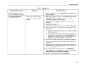
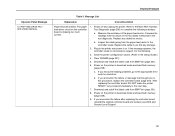
...(page 238). 8. Display Messages Operator Panel Message 088 CONTROL 23.5V CHECK SEE USERS MANUAL (continued) 101 UPPER DRIVER SHORT* SEE USERS MANUAL Table 3. If the message appears, replace the shuttle frame assembly. 1. Download and install the latest code from.... Check the shuttle for resolution. Download and install the latest code from IBM First (page 231). 7. If you encounter loading problems, go to the User's Manual.) 3. Message List Explanation Corrective Action Hammer driver circuits on the printer. If this procedure, replace the controller board (page...
...(page 238). 8. Display Messages Operator Panel Message 088 CONTROL 23.5V CHECK SEE USERS MANUAL (continued) 101 UPPER DRIVER SHORT* SEE USERS MANUAL Table 3. If the message appears, replace the shuttle frame assembly. 1. Download and install the latest code from.... Check the shuttle for resolution. Download and install the latest code from IBM First (page 231). 7. If you encounter loading problems, go to the User's Manual.) 3. Message List Explanation Corrective Action Hammer driver circuits on the printer. If this procedure, replace the controller board (page...
Maintenance Manual
Page 89
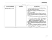
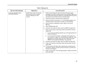
... that brought you encounter loading problems, go to this procedure, replace the controller board (page 319). Operator Panel Message 101 UPPER DRIVER SHORT* SEE USERS MANUAL (continued) Display Messages Table 3. Message List Explanation Corrective Action 11. Download and install the latest code from... IBM First (page 231). 15. Do the following: 12. Power on the printer. Power on the printer in download mode and load flash ...
... that brought you encounter loading problems, go to this procedure, replace the controller board (page 319). Operator Panel Message 101 UPPER DRIVER SHORT* SEE USERS MANUAL (continued) Display Messages Table 3. Message List Explanation Corrective Action 11. Download and install the latest code from... IBM First (page 231). 15. Do the following: 12. Power on the printer. Power on the printer in download mode and load flash ...
Maintenance Manual
Page 90
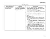
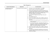
... make the printer READY, but proceed immediately to the appropriate error code for electrical shorts (page 252). 3. Operator Panel Message 102 LOWER DRIVER SHORT * SEE USERS MANUAL Display Messages Table 3. If you encounter the failure after replacing the controller board, reinstall the original controller board ...and contact your DDS and Second Level Support. 90 Download and install the latest code from IBM First (page 231). 8. b. Download and install the latest code from IBM First (page 231). 10. Power on the hammer bank or in the hammer bank power cable ...
... make the printer READY, but proceed immediately to the appropriate error code for electrical shorts (page 252). 3. Operator Panel Message 102 LOWER DRIVER SHORT * SEE USERS MANUAL Display Messages Table 3. If you encounter the failure after replacing the controller board, reinstall the original controller board ...and contact your DDS and Second Level Support. 90 Download and install the latest code from IBM First (page 231). 8. b. Download and install the latest code from IBM First (page 231). 10. Power on the hammer bank or in the hammer bank power cable ...
Maintenance Manual
Page 121
... Operator Panel Message 142 PAP FEED DRIVE FAIL * SEE USERS MANUAL Display Messages Table 3. Clear NVRAM (page 237). 5. a. Download and install the latest code from IBM First (page 231). 6. Refer to the Main Wire Harness Test Diagnostic (page 256) to the Setup Guide.) 4. Replace any damage. 2. Power on the controller ... the controller board, reinstall the original controller board and contact your DDS and Second Level Support. 121 Download and install the latest code from IBM First (page 231). 8. The paper feed driver circuit on the printer in the test diagnostic.
... Operator Panel Message 142 PAP FEED DRIVE FAIL * SEE USERS MANUAL Display Messages Table 3. Clear NVRAM (page 237). 5. a. Download and install the latest code from IBM First (page 231). 6. Refer to the Main Wire Harness Test Diagnostic (page 256) to the Setup Guide.) 4. Replace any damage. 2. Power on the controller ... the controller board, reinstall the original controller board and contact your DDS and Second Level Support. 121 Download and install the latest code from IBM First (page 231). 8. The paper feed driver circuit on the printer in the test diagnostic.
Maintenance Manual
Page 122
...IBM First (page 231). 7. Power off and unplug the printer. Remove the paper guide assembly or top cover to gain access to this procedure, replace the controller board (page 319). Do the following: 4. a. Clear NVRAM (page 237). 6. Operator Panel Message 143 SHUTL DRIVER... FAILED * SEE USERS MANUAL Display Messages Table 3. Message List Explanation Corrective Action Shuttle driver failed. The shuttle driver circuit on . Make sure the shuttle data and power cables are undamaged and...
...IBM First (page 231). 7. Power off and unplug the printer. Remove the paper guide assembly or top cover to gain access to this procedure, replace the controller board (page 319). Do the following: 4. a. Clear NVRAM (page 237). 6. Operator Panel Message 143 SHUTL DRIVER... FAILED * SEE USERS MANUAL Display Messages Table 3. Message List Explanation Corrective Action Shuttle driver failed. The shuttle driver circuit on . Make sure the shuttle data and power cables are undamaged and...
Maintenance Manual
Page 127
...HB NOT INSTALLD" appears on the printer in download mode and load flash memory (page 238). Download and install the latest code from IBM First (page 231). 9. a. After replacing the controller board, DO NOT make the printer READY, but proceed immediately to this procedure,...configuration values. (Refer to the appropriate error code for electrical shorts (page 252). 3. Do the following: 4. Operator Panel Message 148 DRIVER CIRCUIT BAD SEE USERS MANUAL Display Messages Table 3. At the shuttle frame assembly, disconnect the hammer bank logic and power cables. Power ...
...HB NOT INSTALLD" appears on the printer in download mode and load flash memory (page 238). Download and install the latest code from IBM First (page 231). 9. a. After replacing the controller board, DO NOT make the printer READY, but proceed immediately to this procedure,...configuration values. (Refer to the appropriate error code for electrical shorts (page 252). 3. Do the following: 4. Operator Panel Message 148 DRIVER CIRCUIT BAD SEE USERS MANUAL Display Messages Table 3. At the shuttle frame assembly, disconnect the hammer bank logic and power cables. Power ...
Maintenance Manual
Page 199
... to dot row or line to line 3. Dots or characters move up or down from IBM First (page 231). 17. If the power supply fails the check, replace it passes the check, go to the shuttle driver card may also be getting "Table Mismatch" errors. 1. Replace shuttle frame assembly. 199 General Symptom...
... to dot row or line to line 3. Dots or characters move up or down from IBM First (page 231). 17. If the power supply fails the check, replace it passes the check, go to the shuttle driver card may also be getting "Table Mismatch" errors. 1. Replace shuttle frame assembly. 199 General Symptom...
Maintenance Manual
Page 252
...cover during servicing and before you face the printer.) Hold the positive lead for hammer coils shorting to the shuttle frame. Check the shuttle driver circuit board area for maintenance (page 313). 2. Such stray metal pieces can attract metal objects because of concerns about component temperatures.) Do... this check - Install the shuttle cover assembly (page 326). 12. The hammer driver circuit board attached to the shuttle frame assembly can cause electrical shorting and damage to the shuttle assembly. (The hammer...
...cover during servicing and before you face the printer.) Hold the positive lead for hammer coils shorting to the shuttle frame. Check the shuttle driver circuit board area for maintenance (page 313). 2. Such stray metal pieces can attract metal objects because of concerns about component temperatures.) Do... this check - Install the shuttle cover assembly (page 326). 12. The hammer driver circuit board attached to the shuttle frame assembly can cause electrical shorting and damage to the shuttle assembly. (The hammer...
Maintenance Manual
Page 273
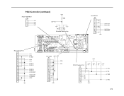
... 3 3 PF 2 4 PF 1 SOFT ID VDD 2.7K 0.1W J9 1 2 3 Software Security Key Host RS422 J15 1 2 NC 3 NC 4 5 6 NC 7 NC 8 9 10 NC DIFF TXD+ DIFF TXD- Phase Driver Port J115 1 2 3 4 5 6 7 8 9 10 11 12 13 14 15 16 17 18 19 20 UD 1 UD 2 PH REF UD 3 UD 4 DIODE 1 DIODE 2 DIODE 3 DIODE 4 N COILTEST CABLE...
... 3 3 PF 2 4 PF 1 SOFT ID VDD 2.7K 0.1W J9 1 2 3 Software Security Key Host RS422 J15 1 2 NC 3 NC 4 5 6 NC 7 NC 8 9 10 NC DIFF TXD+ DIFF TXD- Phase Driver Port J115 1 2 3 4 5 6 7 8 9 10 11 12 13 14 15 16 17 18 19 20 UD 1 UD 2 PH REF UD 3 UD 4 DIODE 1 DIODE 2 DIODE 3 DIODE 4 N COILTEST CABLE...
Maintenance Manual
Page 279
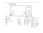
Power Supply: 6500-v20 (Line Filter Area) Cable Assembly AC In Power Supply AC Input J1 AC AC Common Chassis Ground LOAD LOAD 1 2 P1 3 = FAST-ON TERMINAL = RING TERMINAL GND J3 J2 (Phase Driver Control) 1 P101 2 3 (Phase Driver Power) 1 NACFAIL (Not AC Fail) 4 1 PH1 2 3 PH2 4 5 PH3 6 7 PH4 8 9 LDFB 10 2 NSTBY (Not Standby) 5 3 +5 Volts 6 4 +5 Volts...
Power Supply: 6500-v20 (Line Filter Area) Cable Assembly AC In Power Supply AC Input J1 AC AC Common Chassis Ground LOAD LOAD 1 2 P1 3 = FAST-ON TERMINAL = RING TERMINAL GND J3 J2 (Phase Driver Control) 1 P101 2 3 (Phase Driver Power) 1 NACFAIL (Not AC Fail) 4 1 PH1 2 3 PH2 4 5 PH3 6 7 PH4 8 9 LDFB 10 2 NSTBY (Not Standby) 5 3 +5 Volts 6 4 +5 Volts...
Maintenance Manual
Page 312
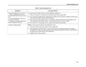
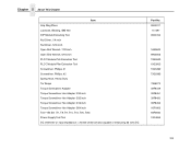
Chapter 5 About This Chapter Item Grip Ring Pliers Lubricant, Bearing, IBM #20 DIP Module Extracting Tool Nut Driver, 1/4 inch Nut Driver, 5/16 inch Open End Wrench, 7/32 inch Open End Wrench, 5/16 inch PLCC Module Pick Extraction Tool PLCC Module Plier Extraction Tool Screwdriver, Phillips, #1 Screwdriver, ...
Chapter 5 About This Chapter Item Grip Ring Pliers Lubricant, Bearing, IBM #20 DIP Module Extracting Tool Nut Driver, 1/4 inch Nut Driver, 5/16 inch Open End Wrench, 7/32 inch Open End Wrench, 5/16 inch PLCC Module Pick Extraction Tool PLCC Module Plier Extraction Tool Screwdriver, Phillips, #1 Screwdriver, ...
Maintenance Manual
Page 355
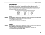
... terminating resistor combinations are suitable for maintenance (page 313). 2. Resistors, Terminating Resistors, Terminating For parallel interface configurations, the printer is not compatible with the interface driver requirements of pull-up and pull-down resistors may be required. 220 ohm pull-up and 330 ohm pull-down alternate terminating resistors are provided...
... terminating resistor combinations are suitable for maintenance (page 313). 2. Resistors, Terminating Resistors, Terminating For parallel interface configurations, the printer is not compatible with the interface driver requirements of pull-up and pull-down resistors may be required. 220 ohm pull-up and 330 ohm pull-down alternate terminating resistors are provided...
Maintenance Manual
Page 387
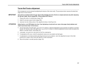
... printer to increase tension. If compression is compressed and only after adjusting the tension by adjusting the tension of the left tractor, use a Torx T-10 driver to increase tension. (See Figure 34.) 5. Adjust the dynamic paper tension (page 384). 3. If compression still occurs, rotate the adjustment screws one detent to rotate... the user reports that might occur in step 3 and call support for further assistance. 8. On the inner side of the right tractor, use a Torx T-10 driver to rotate the adjustment screw clockwise one detent to normal operation (page 314). 387
... printer to increase tension. If compression is compressed and only after adjusting the tension by adjusting the tension of the left tractor, use a Torx T-10 driver to increase tension. (See Figure 34.) 5. Adjust the dynamic paper tension (page 384). 3. If compression still occurs, rotate the adjustment screws one detent to rotate... the user reports that might occur in step 3 and call support for further assistance. 8. On the inner side of the right tractor, use a Torx T-10 driver to rotate the adjustment screw clockwise one detent to normal operation (page 314). 387

Maintenance Manual
Page 417
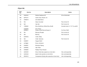
... Assy Screw, Thread Forming, 6-32x.375 (2) Paper Feed Motor Assy, All Except Model v20 Paper Feed Motor Assy, Model v20 6 Ref Motor Pulley, Platen Open, Driver 7 Ref Screw, Hex w/Lock Washer (2) 8 39U2540 Ribbon Guide Cable Assembly, RH 39U2539 Ribbon Guide Cable Assembly, LH 9 54P1453 Platen Open Motor Assembly 10 Ref Washer...
... Assy Screw, Thread Forming, 6-32x.375 (2) Paper Feed Motor Assy, All Except Model v20 Paper Feed Motor Assy, Model v20 6 Ref Motor Pulley, Platen Open, Driver 7 Ref Screw, Hex w/Lock Washer (2) 8 39U2540 Ribbon Guide Cable Assembly, RH 39U2539 Ribbon Guide Cable Assembly, LH 9 54P1453 Platen Open Motor Assembly 10 Ref Washer...
Maintenance Manual
Page 459
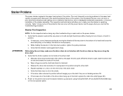
... Stacker First Inspection NOTE: Do this inspection before doing the next step, make sure the stacker is open , slide the drive roller on the driver shaft. a. c. Verify that can find the troubleshooting procedure. Manually retract and hold it to spring back into position along the drive shaft. 2.... Release the drive roller and allow you can occur are OK. Stacker Problems The power stacker augments the paper feed system of the driver shaft. The most frequently occurring problems in the fully down using the ELEVATOR UP and ELEVATOR DOWN keys on the side(s) that there...
... Stacker First Inspection NOTE: Do this inspection before doing the next step, make sure the stacker is open , slide the drive roller on the driver shaft. a. c. Verify that can find the troubleshooting procedure. Manually retract and hold it to spring back into position along the drive shaft. 2.... Release the drive roller and allow you can occur are OK. Stacker Problems The power stacker augments the paper feed system of the driver shaft. The most frequently occurring problems in the fully down using the ELEVATOR UP and ELEVATOR DOWN keys on the side(s) that there...
Maintenance Manual
Page 493
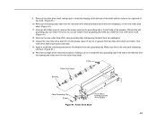
.... (Figure 91.) 11. Discard the old grounding clip, but retain the screw so you can install a new grounding clip when you install the new roller driver shaft. (Figure 91.) 12. Collar Roller Drive Shaft Bearing New Grounding Clip Screw Put a dab of the elevator and the bearing and collar onto the...
.... (Figure 91.) 11. Discard the old grounding clip, but retain the screw so you can install a new grounding clip when you install the new roller driver shaft. (Figure 91.) 12. Collar Roller Drive Shaft Bearing New Grounding Clip Screw Put a dab of the elevator and the bearing and collar onto the...
Maintenance Manual
Page 499
... Shaft) Drive Roller Grease (Shell Darina Grease 1) Bearing, Flanged Bearing Collar Clamp Collar, Setscrew Support Shaft Fence, Wireform Extension Spring Idler Roller Paddle, Power Stacker Driver Shaft (also spared as a lone item) Spacer (also spared as a lone item) Compression Spring (also spared as a lone item) Kit not illustrated Part of item...
... Shaft) Drive Roller Grease (Shell Darina Grease 1) Bearing, Flanged Bearing Collar Clamp Collar, Setscrew Support Shaft Fence, Wireform Extension Spring Idler Roller Paddle, Power Stacker Driver Shaft (also spared as a lone item) Spacer (also spared as a lone item) Compression Spring (also spared as a lone item) Kit not illustrated Part of item...
Maintenance Manual
Page 521
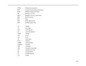
BCOM BCP BHSC BN BNLD BPS BSY BTU BUD CA CC CCF CE CHNG CIR CLK CO COLL COMM CONTLR CMD CNC CPI CR CT CTL Buffered Communication Bi-phase Communications Processor Buffered Hammer Shift Clock Buffered, Low True Buffered, Low True, Lower Driver Bits Per Second Busy British Thermal Unit Buffered Upper Driver Cathode Card Cage Card Cage Fan Customer Engineer Change Circuit Clock Cover Open Collector Communication Controller Command Connector, Connection Characters Per Inch Carriage Return Coaxial/Twinaxial Control 521
BCOM BCP BHSC BN BNLD BPS BSY BTU BUD CA CC CCF CE CHNG CIR CLK CO COLL COMM CONTLR CMD CNC CPI CR CT CTL Buffered Communication Bi-phase Communications Processor Buffered Hammer Shift Clock Buffered, Low True Buffered, Low True, Lower Driver Bits Per Second Busy British Thermal Unit Buffered Upper Driver Cathode Card Cage Card Cage Fan Customer Engineer Change Circuit Clock Cover Open Collector Communication Controller Command Connector, Connection Characters Per Inch Carriage Return Coaxial/Twinaxial Control 521
Maintenance Manual
Page 522
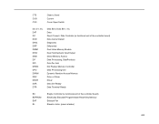
... Hammerbank Input/Output Direct Memory Access Data Processing, DataProducts Dots Per Inch Dot Plucker Memory Controller Data Processing Unit Dynamic Random Access Memory Drive or Driver Driver Data Set Ready Data Terminal Ready EC EEPROM EHF EL Engine Controller (a functional unit of the controller board) Electrically Erasable/Programmable Read-Only Memory Exhaust...
... Hammerbank Input/Output Direct Memory Access Data Processing, DataProducts Dots Per Inch Dot Plucker Memory Controller Data Processing Unit Dynamic Random Access Memory Drive or Driver Driver Data Set Ready Data Terminal Ready EC EEPROM EHF EL Engine Controller (a functional unit of the controller board) Electrically Erasable/Programmable Read-Only Memory Exhaust...
Maintenance Manual
Page 524
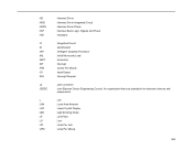
... 524 HD HDIC HDPH HLP HW IC ID IGP IML INST INT IPM I/O IRQ (J) JEDEC L LAN LCD LED LF LO LPI LPM Hammer Driver Hammer Driver Integrated Circuit Hammer Driver Phase Hammer Bank Logic, Signals and Power Hardware Integrated Circuit Identification Intelligent Graphics Processor Initial Microcode Load Instruction Interrupt Inches Per Minute Input...
... 524 HD HDIC HDPH HLP HW IC ID IGP IML INST INT IPM I/O IRQ (J) JEDEC L LAN LCD LED LF LO LPI LPM Hammer Driver Hammer Driver Integrated Circuit Hammer Driver Phase Hammer Bank Logic, Signals and Power Hardware Integrated Circuit Identification Intelligent Graphics Processor Initial Microcode Load Instruction Interrupt Inches Per Minute Input...