
User Guide
Page 5
... options 11 Locating the connectors on the front of your computer 1 Small desktop model computer 2 Desktop model computer 2 Microtower model computer 2 Features 3 Specifications 5 Physical specifications - desktop model 29 Removing the cover 29 Locating components 30 Identifying parts on the...assignments 67 Appendix E. Installing internal options - Installing internal options - Updating System Programs 61 System programs 61 Recovering from the IBM Setup Utility program . . . 55 Using passwords 55 User password 55 Administrator password 56 Setting, changing, and deleting ...
... options 11 Locating the connectors on the front of your computer 1 Small desktop model computer 2 Desktop model computer 2 Microtower model computer 2 Features 3 Specifications 5 Physical specifications - desktop model 29 Removing the cover 29 Locating components 30 Identifying parts on the...assignments 67 Appendix E. Installing internal options - Installing internal options - Updating System Programs 61 System programs 61 Recovering from the IBM Setup Utility program . . . 55 Using passwords 55 User password 55 Administrator password 56 Setting, changing, and deleting ...

User Guide
Page 11
...information about the interrupt and direct memory access channel assignments. v "Chapter 2. v "Chapter 3. v "Appendix D. Installing internal options - desktop model" provides instructions for removing the cover and installing hard disk drives, memory, and adapters in your computer. Installing internal options - v...v "Appendix B. Installing internal options - Notices and trademarks" contains notice and trademark information. © Copyright IBM Corp. 2001 ix How this book This publication provides instructions for your computer. microtower model" provides instructions for ...
...information about the interrupt and direct memory access channel assignments. v "Chapter 2. v "Chapter 3. v "Appendix D. Installing internal options - desktop model" provides instructions for removing the cover and installing hard disk drives, memory, and adapters in your computer. Installing internal options - v...v "Appendix B. Installing internal options - Notices and trademarks" contains notice and trademark information. © Copyright IBM Corp. 2001 ix How this book This publication provides instructions for your computer. microtower model" provides instructions for ...
User Guide
Page 16
... passwords v Support for the addition of the operating system vendor. 4 User Guide Corrections and additions to this publication goes to press. Small desktop model: Three (supports low profile adapters only) - Operating systems (supported) v Microsoft® Windows XP v Microsoft Windows 2000 v Microsoft ...start mode v Diskette and hard disk I/O control v Serial and parallel port I/O control v Security profile by IBM as compatible with preinstalled software. If it does, an operating system, device drivers to change. The operating systems listed here are included...
... passwords v Support for the addition of the operating system vendor. 4 User Guide Corrections and additions to this publication goes to press. Small desktop model: Three (supports low profile adapters only) - Operating systems (supported) v Microsoft® Windows XP v Microsoft Windows 2000 v Microsoft ...start mode v Diskette and hard disk I/O control v Serial and parallel port I/O control v Security profile by IBM as compatible with preinstalled software. If it does, an operating system, device drivers to change. The operating systems listed here are included...
User Guide
Page 17
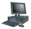
.... At higher altitudes, the maximum air temperatures are reported in a given location might exceed the average values stated because of computers will operate. Overview 5 small desktop model Dimensions Height: 104 mm (4.1 in.) Width: 360 mm (14.2 in.) Depth: 412 mm (16.2 in use. Chapter 1. Note: Power consumption and heat output vary...
.... At higher altitudes, the maximum air temperatures are reported in a given location might exceed the average values stated because of computers will operate. Overview 5 small desktop model Dimensions Height: 104 mm (4.1 in.) Width: 360 mm (14.2 in.) Depth: 412 mm (16.2 in use. Chapter 1. Note: Power consumption and heat output vary...

User Guide
Page 18
... reflections and other nearby noise sources. At higher altitudes, the maximum air temperatures are reported in ) Weight Minimum configuration as a Class A or Class B digital device. desktop model Dimensions Height: 140 mm (5.5 in.) Width: 425 mm (16.7 in.) Depth: 425 mm (16.7 in accordance with ISO 9296. The declared sound-power levels...
... reflections and other nearby noise sources. At higher altitudes, the maximum air temperatures are reported in ) Weight Minimum configuration as a Class A or Class B digital device. desktop model Dimensions Height: 140 mm (5.5 in.) Width: 425 mm (16.7 in.) Depth: 425 mm (16.7 in accordance with ISO 9296. The declared sound-power levels...

User Guide
Page 20
...instructions that come with the option. When you add an option, do so. 8 User Guide Accelerated graphics port (AGP) adapters - Small desktop models support low profile adapters only - Peripheral component interconnect (PCI) adapters - CD drive and DVD drive - Audio devices, such as external ... information about available options, see the following telephone numbers: v Within the United States, call 1-800-565-3344 or 1-800-IBM-4YOU. Handling static-sensitive devices Static electricity, although harmless to do not open the static-protective package containing the option until you...
...instructions that come with the option. When you add an option, do so. 8 User Guide Accelerated graphics port (AGP) adapters - Small desktop models support low profile adapters only - Peripheral component interconnect (PCI) adapters - CD drive and DVD drive - Audio devices, such as external ... information about available options, see the following telephone numbers: v Within the United States, call 1-800-565-3344 or 1-800-IBM-4YOU. Handling static-sensitive devices Static electricity, although harmless to do not open the static-protective package containing the option until you...
User Guide
Page 23
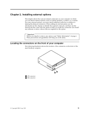
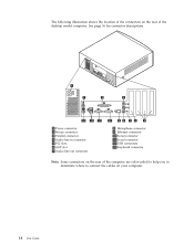
... software in addition to which you make the connection and install any option, read "Safety Information" on the front of the small desktop computer. 1 USB connector 2 USB connector © Copyright IBM Corp. 2001 11 These precautions and guidelines will help you can attach external options, such as external speakers, a printer, or a scanner...
... software in addition to which you make the connection and install any option, read "Safety Information" on the front of the small desktop computer. 1 USB connector 2 USB connector © Copyright IBM Corp. 2001 11 These precautions and guidelines will help you can attach external options, such as external speakers, a printer, or a scanner...

User Guide
Page 24
Note: Not all computer models will have the following illustration shows the location of the connectors on the front of the desktop computer. 1 USB connector 2 USB connector The following connectors. 12 User Guide 1 IEEE 1394 connector 2 Microphone connector 3 Headphone connector 4 USB connector 5 USB connector The following illustration shows the location of the connectors on the front of the microtower computer.
Note: Not all computer models will have the following illustration shows the location of the connectors on the front of the desktop computer. 1 USB connector 2 USB connector The following connectors. 12 User Guide 1 IEEE 1394 connector 2 Microphone connector 3 Headphone connector 4 USB connector 5 USB connector The following illustration shows the location of the connectors on the front of the microtower computer.

User Guide
Page 25
... rear of the connectors on your computer. Locating the connectors on the rear of your computer The following illustration shows the location of the small desktop model computer. Installing external options 13
... rear of the connectors on your computer. Locating the connectors on the rear of your computer The following illustration shows the location of the small desktop model computer. Installing external options 13
User Guide
Page 26
See page 16 for connector descriptions. 1 Power connector 2 Mouse connector 3 Parallel connector 4 Audio line in connector 5 PCI slots 6 AGP slot 7 Audio line out connector 8 Microphone connector 9 Ethernet connector 10 Serial connector 11 Serial connector 12 USB connectors 13 Keyboard connector Note: Some connectors on the rear of the computer are color-coded to help you to determine where to connect the cables on the rear of the connectors on your computer. 14 User Guide The following illustration shows the location of the desktop model computer.
See page 16 for connector descriptions. 1 Power connector 2 Mouse connector 3 Parallel connector 4 Audio line in connector 5 PCI slots 6 AGP slot 7 Audio line out connector 8 Microphone connector 9 Ethernet connector 10 Serial connector 11 Serial connector 12 USB connectors 13 Keyboard connector Note: Some connectors on the rear of the computer are color-coded to help you to determine where to connect the cables on the rear of the connectors on your computer. 14 User Guide The following illustration shows the location of the desktop model computer.
User Guide
Page 29
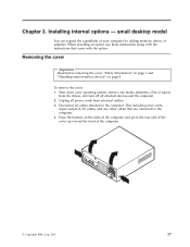
... adapters. This includes power cords, input/output (I/O) cables, and any media (diskettes, CDs, or tapes) from electrical outlets. 3. small desktop model You can expand the capabilities of the computer. © Copyright IBM Corp. 2001 17 Removing the cover Important Read before removing the cover "Safety Information" on page v and "Handling static-sensitive...
... adapters. This includes power cords, input/output (I/O) cables, and any media (diskettes, CDs, or tapes) from electrical outlets. 3. small desktop model You can expand the capabilities of the computer. © Copyright IBM Corp. 2001 17 Removing the cover Important Read before removing the cover "Safety Information" on page v and "Handling static-sensitive...

User Guide
Page 31
... the location of parts on page 17. small desktop model 19 See the following rules apply: v Fill each system memory connector sequentially, starting at DIMM 1 v Use 3.3 V, synchronous, 168-pin, unbuffered, 133 MHz, nonparity, synchronous dynamic random access memory (SDRAM) v Use 64 MB, 128 MB, 256 MB, or 512 MB DIMMs in -line memory modules (DIMMs) that...
... the location of parts on page 17. small desktop model 19 See the following rules apply: v Fill each system memory connector sequentially, starting at DIMM 1 v Use 3.3 V, synchronous, 168-pin, unbuffered, 133 MHz, nonparity, synchronous dynamic random access memory (SDRAM) v Use 64 MB, 128 MB, 256 MB, or 512 MB DIMMs in -line memory modules (DIMMs) that...

User Guide
Page 33
Remove the support bar by pulling it is latched in the up position. Chapter 3. small desktop model 21 Repeat this procedure for the remaining drive bay. 3. Installing internal options - Pivot one of the drive bay latch handles toward the front of the computer and then pivot the drive bay cage upward, as shown, until it outward from the computer. 2.
Remove the support bar by pulling it is latched in the up position. Chapter 3. small desktop model 21 Repeat this procedure for the remaining drive bay. 3. Installing internal options - Pivot one of the drive bay latch handles toward the front of the computer and then pivot the drive bay cage upward, as shown, until it outward from the computer. 2.

User Guide
Page 35
... (standard in the accessible bay: bay 2. Install removable media (tape or CD) drives in some of the drive bays. small desktop model 23 Installing internal drives This section provides information and instructions for installing and removing internal drives. Internal drives are referred to note ...mm (1.0 in .) 3 Bay 3 - You can install in each bay. Internal drives are greater than 41.3 mm (1.6 in bays. Installing internal options - The following IBM-installed drives: v A 3.5-inch diskette drive in bay 1 v A CD drive or DVD drive in bay 2 v A 3.5-inch hard disk drive in bay 3 Bays...
... (standard in the accessible bay: bay 2. Install removable media (tape or CD) drives in some of the drive bays. small desktop model 23 Installing internal drives This section provides information and instructions for installing and removing internal drives. Internal drives are referred to note ...mm (1.0 in .) 3 Bay 3 - You can install in each bay. Internal drives are greater than 41.3 mm (1.6 in bays. Installing internal options - The following IBM-installed drives: v A 3.5-inch diskette drive in bay 1 v A CD drive or DVD drive in bay 2 v A 3.5-inch hard disk drive in bay 3 Bays...

User Guide
Page 37
... back into place. then attach and tighten the nuts with another option, go to "Replacing the cover and connecting the cables" on page 17). 2. small desktop model 25 d. Use a tool, such as a screwdriver, to the drive. 8. Installing internal options - Remove the cover (see "Replacing the cover and connecting the cables" on...
... back into place. then attach and tighten the nuts with another option, go to "Replacing the cover and connecting the cables" on page 17). 2. small desktop model 25 d. Use a tool, such as a screwdriver, to the drive. 8. Installing internal options - Remove the cover (see "Replacing the cover and connecting the cables" on...

User Guide
Page 39
Chapter 3. Installing external options" on page 55. To update the configuration, see "Chapter 6. small desktop model 27 Installing internal options - See "Chapter 2. Reconnect the external cables and power cords to the computer. 3. Position the cover over the chassis and pivot it down over the computer until it snaps into place. 4. Using the IBM Setup Utility program" on page 11. 5.
Chapter 3. Installing external options" on page 55. To update the configuration, see "Chapter 6. small desktop model 27 Installing internal options - See "Chapter 2. Reconnect the external cables and power cords to the computer. 3. Position the cover over the chassis and pivot it down over the computer until it snaps into place. 4. Using the IBM Setup Utility program" on page 11. 5.
User Guide
Page 41
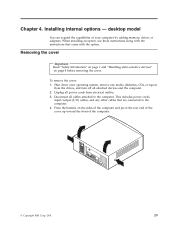
... includes power cords, input/output (I/O) cables, and any media (diskettes, CDs, or tapes) from the drives, and turn off all power cords from electrical outlets. 3. desktop model You can expand the capabilities of the computer. © Copyright...
... includes power cords, input/output (I/O) cables, and any media (diskettes, CDs, or tapes) from the drives, and turn off all power cords from electrical outlets. 3. desktop model You can expand the capabilities of the computer. © Copyright...
User Guide
Page 43
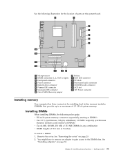
...-pin, unbuffered, 133 MHz nonparity synchronous dynamic random access memory (SDRAM) v Use 64 MB, 128 MB, 256 MB, or 512 MB DIMMs in -line memory modules (DIMMs) that provide up to a maximum of 1.5 GB of 38.1 mm (1.5 inches) To install a DIMM: 1. desktop model 31 Installing DIMMs When installing DIMMs, the following illustration for installing dual in...
...-pin, unbuffered, 133 MHz nonparity synchronous dynamic random access memory (SDRAM) v Use 64 MB, 128 MB, 256 MB, or 512 MB DIMMs in -line memory modules (DIMMs) that provide up to a maximum of 1.5 GB of 38.1 mm (1.5 inches) To install a DIMM: 1. desktop model 31 Installing DIMMs When installing DIMMs, the following illustration for installing dual in...

User Guide
Page 45
... system board. 5. Installing internal drives This section provides information and instructions for the appropriate expansion slot. 3. Installing internal options - Install the adapter slot cover latch. desktop model 33 Remove the adapter slot cover latch and the slot cover for installing and removing internal drives. Install the adapter into the appropriate slot...
... system board. 5. Installing internal drives This section provides information and instructions for the appropriate expansion slot. 3. Installing internal options - Install the adapter slot cover latch. desktop model 33 Remove the adapter slot cover latch and the slot cover for installing and removing internal drives. Install the adapter into the appropriate slot...

User Guide
Page 47
... gently prying it is latched in the up right position. 6. Install removable media (tape or CD) drives in .) high cannot be installed. 2. v If it loose. 5. desktop model 35 Drives that you are installing is a removable-media drive, remove the bay panel from the drive. 3. Installing a drive To install an internal drive...
... gently prying it is latched in the up right position. 6. Install removable media (tape or CD) drives in .) high cannot be installed. 2. v If it loose. 5. desktop model 35 Drives that you are installing is a removable-media drive, remove the bay panel from the drive. 3. Installing a drive To install an internal drive...

