Hardware Maintenance Manual
Page 1
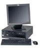
ThinkCentre™ Hardware Maintenance Manual Types 8128, 8185, 8186, 8187, 8188, 8189, Types 8190, 8192, 8193, 8194, 8195, 8196, Types 8197, 8413, 8414, 8415, 8430, 8431 Types 8432, 8433
ThinkCentre™ Hardware Maintenance Manual Types 8128, 8185, 8186, 8187, 8188, 8189, Types 8190, 8192, 8193, 8194, 8195, 8196, Types 8197, 8413, 8414, 8415, 8430, 8431 Types 8432, 8433

Hardware Maintenance Manual
Page 3
ThinkCentre™ Hardware Maintenance Manual Types 8128, 8185, 8186, 8187, 8188, 8189, Types 8190, 8192, 8193, 8194, 8195, 8196, Types 8197, 8413, 8414, 8415, 8430, 8431 Types 8432, 8433
ThinkCentre™ Hardware Maintenance Manual Types 8128, 8185, 8186, 8187, 8188, 8189, Types 8190, 8192, 8193, 8194, 8195, 8196, Types 8197, 8413, 8414, 8415, 8430, 8431 Types 8432, 8433

Hardware Maintenance Manual
Page 5
... 8. hard drive 18 Viewing the test log 18 Chapter 5. About this manual . . . . . 1 Important Safety Information 1 Chapter 2. General information . . . . . 3 Features 3 Physical specifications 5 Types 8185, 8186, 8192, 8413, and 8430 . . . . . 6 Types 8128, 8187, 8188, 8193, 8414, and 8431 . . . 7 Types 8189,...8195, 8415, 8432, and 8433 8 Types 8196 and 8197 9 Chapter 3. IBM Setup Utility program 19 Starting the IBM Setup Utility program . . . . . 19 Viewing and changing settings 19 Exiting from the IBM Setup Utility program . . . 20 Using passwords 20 User password 20 Administrator ...
... 8. hard drive 18 Viewing the test log 18 Chapter 5. About this manual . . . . . 1 Important Safety Information 1 Chapter 2. General information . . . . . 3 Features 3 Physical specifications 5 Types 8185, 8186, 8192, 8413, and 8430 . . . . . 6 Types 8128, 8187, 8188, 8193, 8414, and 8431 . . . 7 Types 8189,...8195, 8415, 8432, and 8433 8 Types 8196 and 8197 9 Chapter 3. IBM Setup Utility program 19 Starting the IBM Setup Utility program . . . . . 19 Viewing and changing settings 19 Exiting from the IBM Setup Utility program . . . 20 Using passwords 20 User password 20 Administrator ...

Hardware Maintenance Manual
Page 6
Parts listing 119 Type 8128 119 Type 8185 121 Type 8186 130 Type 8187 134 Type 8188 149 Type 8189 158 Type 8190 Type 8192 Type 8193 Type 8194 Type 8195 Type 8196 Type 8197 Type 8413 Type 8414 ... (flashing) BIOS from a diskette or CD-ROM Updating (flashing) BIOS from your comments 280 Problem determination tips 281 Notices 281 Trademarks 282 iv Hardware Maintenance Manual
Parts listing 119 Type 8128 119 Type 8185 121 Type 8186 130 Type 8187 134 Type 8188 149 Type 8189 158 Type 8190 Type 8192 Type 8193 Type 8194 Type 8195 Type 8196 Type 8197 Type 8413 Type 8414 ... (flashing) BIOS from a diskette or CD-ROM Updating (flashing) BIOS from your comments 280 Problem determination tips 281 Notices 281 Trademarks 282 iv Hardware Maintenance Manual

Hardware Maintenance Manual
Page 7
... Anweisung ausführen. About this manual This manual contains service and reference information for trained servicers who are familiar with advanced diagnostic tests to read all caution and danger statements in this manual along with IBM Personal Computer products. Important Safety Information Be... di leggere tutti gli avvisi di attenzione e di pericolo prima di effettuare qualsiasi operazione. © Copyright IBM Corp. 2005 1 This manual is intended for IBM® computer Types 8128, 8185, 8186, 8187, 8188, 8189, 8190, 8192 8193, 8194, 8195, 8196, 8197, 8413, 8414, 8415, 8430...
... Anweisung ausführen. About this manual This manual contains service and reference information for trained servicers who are familiar with advanced diagnostic tests to read all caution and danger statements in this manual along with IBM Personal Computer products. Important Safety Information Be... di leggere tutti gli avvisi di attenzione e di pericolo prima di effettuare qualsiasi operazione. © Copyright IBM Corp. 2005 1 This manual is intended for IBM® computer Types 8128, 8185, 8186, 8187, 8188, 8189, 8190, 8192 8193, 8194, 8195, 8196, 8197, 8413, 8414, 8415, 8430...
Hardware Maintenance Manual
Page 10
...have these operating systems. v Microsoft® Windows® XP Home v Microsoft Windows XP Professional v Microsoft Windows 2000 4 Hardware Maintenance Manual v System Management (SM) BIOS and SM software v Ability to support built-in , line out, and microphone) Expansion v Empty ... only) Power v 200 - 230 W power supply with preinstalled software. Operating systems (preinstalled) (varies by device IBM preinstalled software The computer might come with manual voltage selection switch (depending on rear panel) v PS/2® mouse connector v PS/2 keyboard connector v Ethernet connector...
...have these operating systems. v Microsoft® Windows® XP Home v Microsoft Windows XP Professional v Microsoft Windows 2000 4 Hardware Maintenance Manual v System Management (SM) BIOS and SM software v Ability to support built-in , line out, and microphone) Expansion v Empty ... only) Power v 200 - 230 W power supply with preinstalled software. Operating systems (preinstalled) (varies by device IBM preinstalled software The computer might come with manual voltage selection switch (depending on rear panel) v PS/2® mouse connector v PS/2 keyboard connector v Ethernet connector...
Hardware Maintenance Manual
Page 12
... optional features installed and the power-management optional features in a given location might exceed the average values stated because of computers will operate. 6 Hardware Maintenance Manual For microprocessors greater than or equal to 2.8 GHz: Average sound-pressure levels: At operator position: Idle: 29 dBA Operating: 31 dBA At bystander position - 1 meter...
... optional features installed and the power-management optional features in a given location might exceed the average values stated because of computers will operate. 6 Hardware Maintenance Manual For microprocessors greater than or equal to 2.8 GHz: Average sound-pressure levels: At operator position: Idle: 29 dBA Operating: 31 dBA At bystander position - 1 meter...
Hardware Maintenance Manual
Page 14
...: 785 Btu/hr (230 watts) Weight Airflow Minimum configuration as shipped: 0.08 kVA Maximum configuration: 0.3 kVA Note: These levels were measured in use. 8 Hardware Maintenance Manual Types 8189, 8190, 8194, 8195, 8415, 8432, and 8433 This section lists the physical specifications for the computer.
...: 785 Btu/hr (230 watts) Weight Airflow Minimum configuration as shipped: 0.08 kVA Maximum configuration: 0.3 kVA Note: These levels were measured in use. 8 Hardware Maintenance Manual Types 8189, 8190, 8194, 8195, 8415, 8432, and 8433 This section lists the physical specifications for the computer.

Hardware Maintenance Manual
Page 16
10 Hardware Maintenance Manual
10 Hardware Maintenance Manual
Hardware Maintenance Manual
Page 18
...you determine that all external devices. 2. 001 1. Make sure that the monitor is working properly. Power-on page 15. YES, continue to the manual for the fan(s). NO, make sure it is working properly, make sure that device might be defective. 12 Hardware Maintenance... Manual Refer to 004 . YES, continue to 005 . v If an installed device is not recognized by the diagnostics program, that the monitor is properly connected to Chapter 4, "IBM Enhanced Diagnostics," on all cables to 003 . 003 IS ANYTHING...
...you determine that all external devices. 2. 001 1. Make sure that the monitor is working properly. Power-on page 15. YES, continue to the manual for the fan(s). NO, make sure it is working properly, make sure that device might be defective. 12 Hardware Maintenance... Manual Refer to 004 . YES, continue to 005 . v If an installed device is not recognized by the diagnostics program, that the monitor is properly connected to Chapter 4, "IBM Enhanced Diagnostics," on all cables to 003 . 003 IS ANYTHING...

Hardware Maintenance Manual
Page 20
14 Hardware Maintenance Manual
14 Hardware Maintenance Manual
Hardware Maintenance Manual
Page 22
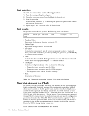
.... Modify the FDAT.INI file in the FDAT.INI. Open the corresponding test category. 2. v Date: Contains the date on the specified IBM computer. - Diagnostics were run on a fixed-disk drive and is recorded correctly. Diagnostics were run on which corresponds to enable or disable ... FDAT uses information supplied by >>. Test selection To select one or more tests, use the following subtests and features. 16 Hardware Maintenance Manual Note: See "Diagnostic error codes" on page 70 for and report most commonly found errors on the specified date. - Test results ...
.... Modify the FDAT.INI file in the FDAT.INI. Open the corresponding test category. 2. v Date: Contains the date on the specified IBM computer. - Diagnostics were run on a fixed-disk drive and is recorded correctly. Diagnostics were run on which corresponds to enable or disable ... FDAT uses information supplied by >>. Test selection To select one or more tests, use the following subtests and features. 16 Hardware Maintenance Manual Note: See "Diagnostic error codes" on page 70 for and report most commonly found errors on the specified date. - Test results ...
Hardware Maintenance Manual
Page 24
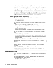
... and follow the instructions. Viewing the test log Errors reported by the program as a failed test. v Press F3 to print the file. 18 Hardware Maintenance Manual v Press F3 again to save the file to diskette or F2 to activate the log file.
... and follow the instructions. Viewing the test log Errors reported by the program as a failed test. v Press F3 to print the file. 18 Hardware Maintenance Manual v Press F3 again to save the file to diskette or F2 to activate the log file.
Hardware Maintenance Manual
Page 26
...deleting a password To set either one, read the following : Note: A password can type either type to seven characters (A- Start the IBM Setup Utility program (see an error message. Using passwords The use of up to use your administrator password. However, if you must use ...the computer. If both the user and administrator passwords are two kinds of the screen. 20 Hardware Maintenance Manual Read the information displayed on page 19). 2. User password The user password feature deters unauthorized persons from changing configuration settings. After you...
...deleting a password To set either one, read the following : Note: A password can type either type to seven characters (A- Start the IBM Setup Utility program (see an error message. Using passwords The use of up to use your administrator password. However, if you must use ...the computer. If both the user and administrator passwords are two kinds of the screen. 20 Hardware Maintenance Manual Read the information displayed on page 19). 2. User password The user password feature deters unauthorized persons from changing configuration settings. After you...
Hardware Maintenance Manual
Page 28
...device from this procedure to the default settings, select Load Default Settings on the Exit menu. 22 Hardware Maintenance Manual Start the IBM Setup Utility program (see "Starting the IBM Setup Utility program" on the right side of the following prompt on the logo screen: (To interrupt normal ... When the Startup Interrupt Menu displays, press F12. 5. If you have changed these settings and want to return to startup from the IBM Setup Utility menu and then Save Settings or Save and exit the Setup Utility. Changing the startup device sequence To view or permanently change ...
...device from this procedure to the default settings, select Load Default Settings on the Exit menu. 22 Hardware Maintenance Manual Start the IBM Setup Utility program (see "Starting the IBM Setup Utility program" on the right side of the following prompt on the logo screen: (To interrupt normal ... When the Startup Interrupt Menu displays, press F12. 5. If you have changed these settings and want to return to startup from the IBM Setup Utility menu and then Save Settings or Save and exit the Setup Utility. Changing the startup device sequence To view or permanently change ...
Hardware Maintenance Manual
Page 30
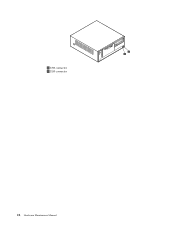
1 USB connector 2 USB connector 24 Hardware Maintenance Manual
1 USB connector 2 USB connector 24 Hardware Maintenance Manual
Hardware Maintenance Manual
Page 32
1 USB connector 2 USB connector 26 Hardware Maintenance Manual
1 USB connector 2 USB connector 26 Hardware Maintenance Manual
Hardware Maintenance Manual
Page 34
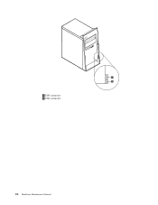
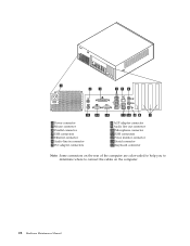
1 Power connector 2 Mouse connector 3 Parallel connector 4 USB connectors 5 Ethernet connector 6 Audio line in connector 7 PCI adapter connectors 8 AGP adapter connector 9 Audio line out connector 10 Microphone connector 11 USB connectors 12 VGA monitor connector 13 Serial connector 14 Keyboard connector Note: Some connectors on the rear of the computer are color-coded to help you to determine where to connect the cables on the computer. 28 Hardware Maintenance Manual
1 Power connector 2 Mouse connector 3 Parallel connector 4 USB connectors 5 Ethernet connector 6 Audio line in connector 7 PCI adapter connectors 8 AGP adapter connector 9 Audio line out connector 10 Microphone connector 11 USB connectors 12 VGA monitor connector 13 Serial connector 14 Keyboard connector Note: Some connectors on the rear of the computer are color-coded to help you to determine where to connect the cables on the computer. 28 Hardware Maintenance Manual
Hardware Maintenance Manual
Page 36
... 12 Audio line in connector 13 AGP adapter connector 14 PCI adapter connectors Note: Some connectors on the rear of the computer. 30 Hardware Maintenance Manual Shut down your operating system, remove any other cables that are color-coded to help you to determine where to the computer. Press the buttons...
... 12 Audio line in connector 13 AGP adapter connector 14 PCI adapter connectors Note: Some connectors on the rear of the computer. 30 Hardware Maintenance Manual Shut down your operating system, remove any other cables that are color-coded to help you to determine where to the computer. Press the buttons...
Hardware Maintenance Manual
Page 38
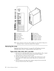
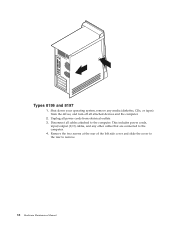
This includes power cords, input/output (I/O) cables, and any media (diskettes, CDs, or tapes) from electrical outlets. 3. Unplug all power cords from the drives, and turn off all cables attached to the computer. Shut down your operating system, remove any other cables that are connected to remove. 32 Hardware Maintenance Manual Remove the two screws at the rear of the left side cover and slide the cover to the rear to the computer. 4. Types 8196 and 8197 1. Disconnect all attached devices and the computer. 2.
This includes power cords, input/output (I/O) cables, and any media (diskettes, CDs, or tapes) from electrical outlets. 3. Unplug all power cords from the drives, and turn off all cables attached to the computer. Shut down your operating system, remove any other cables that are connected to remove. 32 Hardware Maintenance Manual Remove the two screws at the rear of the left side cover and slide the cover to the rear to the computer. 4. Types 8196 and 8197 1. Disconnect all attached devices and the computer. 2.


