

Service Guide
Page 4
Note: Before using this document is available at http://www.ibm.com/support/. Use, duplication or disclosure restricted by GSA ADP Schedule Contract with IBM Corp. The most recent version of this information and the product it supports, read the general information in Appendix B, "Notices," on page 183. Fourth Edition (June 2007) © Copyright International Business Machines Corporation 2006. US Government Users Restricted Rights - All rights reserved.
Note: Before using this document is available at http://www.ibm.com/support/. Use, duplication or disclosure restricted by GSA ADP Schedule Contract with IBM Corp. The most recent version of this information and the product it supports, read the general information in Appendix B, "Notices," on page 183. Fourth Edition (June 2007) © Copyright International Business Machines Corporation 2006. US Government Users Restricted Rights - All rights reserved.
Service Guide
Page 5
...Using the Configuration/Setup Utility program 18 Using the ServeRAID configuration programs 18 Using the baseboard management controller 21 Updating the UUID 33 Updating the DMI/SMBIOS data 33 Chapter 3. Removing and replacing server components 35 Installation guidelines 35 System... the Remote Supervisor Adapter II SlimLine 49 Removing the ServeRAID SAS controller 50 Installing a ServeRAID SAS controller 51 © Copyright IBM Corp. 2006 iii Introduction 1 Related documentation 1 Notices and statements in this document 2 Features and specifications 4 Server controls, LEDs...
...Using the Configuration/Setup Utility program 18 Using the ServeRAID configuration programs 18 Using the baseboard management controller 21 Updating the UUID 33 Updating the DMI/SMBIOS data 33 Chapter 3. Removing and replacing server components 35 Installation guidelines 35 System... the Remote Supervisor Adapter II SlimLine 49 Removing the ServeRAID SAS controller 50 Installing a ServeRAID SAS controller 51 © Copyright IBM Corp. 2006 iii Introduction 1 Related documentation 1 Notices and statements in this document 2 Features and specifications 4 Server controls, LEDs...
Service Guide
Page 7
... log messages 157 IPMI BMC system-error log messages 164 BIOS-logged BMC system-error log messages 173 Solving SCSI problems 175 Solving power problems 175 Solving Ethernet controller problems 176 Solving undetermined problems 177 Problem determination tips 178 Calling IBM for Interference (VCCI) statement ... Japanese Voluntary Control Council for service 178 Appendix A. Getting help and technical assistance 181 Before you call 181 Using the documentation 181 Getting help and information from the World Wide Web 182 Software service and support 182 Hardware service and support ...
... log messages 157 IPMI BMC system-error log messages 164 BIOS-logged BMC system-error log messages 173 Solving SCSI problems 175 Solving power problems 175 Solving Ethernet controller problems 176 Solving undetermined problems 177 Problem determination tips 178 Calling IBM for Interference (VCCI) statement ... Japanese Voluntary Control Council for service 178 Appendix A. Getting help and technical assistance 181 Before you call 181 Using the documentation 181 Getting help and information from the World Wide Web 182 Software service and support 182 Hardware service and support ...
Service Guide
Page 10
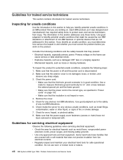
... this section addresses only those items. Use good judgment to help you identify potential unsafe conditions in this section to identify potential unsafe conditions that might be caused by non-IBM alterations or attachment of fire or smoke damage. 7. Check for trained service technicians. viii IBM System x3655 Type 7985: Problem Determination and Service Guide Inspecting...
... this section addresses only those items. Use good judgment to help you identify potential unsafe conditions in this section to identify potential unsafe conditions that might be caused by non-IBM alterations or attachment of fire or smoke damage. 7. Check for trained service technicians. viii IBM System x3655 Type 7985: Problem Determination and Service Guide Inspecting...

Service Guide
Page 11
... as power supplies, pumps, blowers, fans, and motor generators, do not service these components outside of their normal operating locations. Do not use caution, turn off the wall box that it touches a live electrical circuit. v Do not work near power supplies, or remove or install... and equipment frames. v Some rubber floor mats contain small conductive fibers to work on equipment that could cause an electrical shock. - v Use extreme care when measuring high voltages. v Do not touch the reflective surface of a dental mirror to a live electrical circuit. If you ...
... as power supplies, pumps, blowers, fans, and motor generators, do not service these components outside of their normal operating locations. Do not use caution, turn off the wall box that it touches a live electrical circuit. v Do not work near power supplies, or remove or install... and equipment frames. v Some rubber floor mats contain small conductive fibers to work on equipment that could cause an electrical shock. - v Use extreme care when measuring high voltages. v Do not touch the reflective surface of a dental mirror to a live electrical circuit. If you ...
Service Guide
Page 12
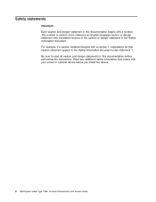
Read any additional safety information that caution statement appear in the Safety Information document under statement 1. x IBM System x3655 Type 7985: Problem Determination and Service Guide Be sure to cross reference an English-language caution or danger statement with translated versions... a number. Safety statements Important: Each caution and danger statement in this documentation before you install the device. This number is used to read all caution and danger statements in this documentation begins with your server or optional device before performing the instructions.
Read any additional safety information that caution statement appear in the Safety Information document under statement 1. x IBM System x3655 Type 7985: Problem Determination and Service Guide Be sure to cross reference an English-language caution or danger statement with translated versions... a number. Safety statements Important: Each caution and danger statement in this documentation before you install the device. This number is used to read all caution and danger statements in this documentation begins with your server or optional device before performing the instructions.

Service Guide
Page 13
v Never turn on this product or attached devices. v Disconnect the attached power cords, telecommunications systems, networks, and modems before you open the device covers, unless instructed otherwise in the following table when installing, moving, or opening ...outlet. To avoid a shock hazard: v Do not connect or disconnect any equipment that will be attached to connectors. 4. To Disconnect: 1. v When possible, use one hand only to outlet. 5. Attach power cords to connect or disconnect signal cables. v Connect all power cords to devices. 3. First, attach all cables ...
v Never turn on this product or attached devices. v Disconnect the attached power cords, telecommunications systems, networks, and modems before you open the device covers, unless instructed otherwise in the following table when installing, moving, or opening ...outlet. To avoid a shock hazard: v Do not connect or disconnect any equipment that will be attached to connectors. 4. To Disconnect: 1. v When possible, use one hand only to outlet. 5. Attach power cords to connect or disconnect signal cables. v Connect all power cords to devices. 3. First, attach all cables ...
Service Guide
Page 14
... or immerse into water v Heat to more than 100°C (212°F) v Repair or disassemble Dispose of . xii IBM System x3655 Type 7985: Problem Determination and Service Guide Statement 2: CAUTION: When replacing the lithium battery, use only IBM Part Number 33F8354 or an equivalent type battery recommended by the manufacturer. The battery contains lithium and can...
... or immerse into water v Heat to more than 100°C (212°F) v Repair or disassemble Dispose of . xii IBM System x3655 Type 7985: Problem Determination and Service Guide Statement 2: CAUTION: When replacing the lithium battery, use only IBM Part Number 33F8354 or an equivalent type battery recommended by the manufacturer. The battery contains lithium and can...
Service Guide
Page 15
... the covers. Statement 3: CAUTION: When laser products (such as CD-ROMs, DVD drives, fiber optic devices, or transmitters) are no serviceable parts inside the device. v Use of controls or adjustments or performance of the laser product could result in hazardous radiation exposure.
... the covers. Statement 3: CAUTION: When laser products (such as CD-ROMs, DVD drives, fiber optic devices, or transmitters) are no serviceable parts inside the device. v Use of controls or adjustments or performance of the laser product could result in hazardous radiation exposure.
Service Guide
Page 16
Statement 4: ≥ 18 kg (39.7 lb) ≥ 32 kg (70.5 lb) CAUTION: Use safe practices when lifting. Statement 5: ≥ 55 kg (121.2 lb) CAUTION: The power control button on the device and the power switch on the power supply do not turn off the electrical current supplied to the device. The device also might have more than one power cord. To remove all electrical current from the device, ensure that all power cords are disconnected from the power source. 2 1 xiv IBM System x3655 Type 7985: Problem Determination and Service Guide
Statement 4: ≥ 18 kg (39.7 lb) ≥ 32 kg (70.5 lb) CAUTION: Use safe practices when lifting. Statement 5: ≥ 55 kg (121.2 lb) CAUTION: The power control button on the device and the power switch on the power supply do not turn off the electrical current supplied to the device. The device also might have more than one power cord. To remove all electrical current from the device, ensure that all power cords are disconnected from the power source. 2 1 xiv IBM System x3655 Type 7985: Problem Determination and Service Guide
Service Guide
Page 17
Statement 26: CAUTION: Do not place any object on an IT power distribution system whose maximum phase-to-phase voltage is 240 V under any distribution fault condition. There are present inside these parts, contact a service technician. Safety xv Hazardous ...voltage, current, and energy levels are no serviceable parts inside any part that has this label attached. Attention: This server is suitable for use on top of these components. If you suspect a problem with one of rack-mounted devices. Statement 8: CAUTION: Never remove the cover on a power supply or...
Statement 26: CAUTION: Do not place any object on an IT power distribution system whose maximum phase-to-phase voltage is 240 V under any distribution fault condition. There are present inside these parts, contact a service technician. Safety xv Hazardous ...voltage, current, and energy levels are no serviceable parts inside any part that has this label attached. Attention: This server is suitable for use on top of these components. If you suspect a problem with one of rack-mounted devices. Statement 8: CAUTION: Never remove the cover on a power supply or...
Service Guide
Page 19
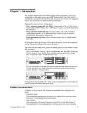
... provides general information about the terms of warranty service that is designated for installing some optional devices. If IBM installs a Tier 1 CRU at no additional charge, under the type of the warranty and getting service and...models and 3.5-inch models are used to help you install an optional tape drive, the tape drive occupies two of Tier 1 CRUs is in your responsibility. Replaceable components are based on the IBM System x™ Documentation CD. Introduction...by trained service technicians. v User's Guide This document is your IBM® System x3655 Type 7985 server.
... provides general information about the terms of warranty service that is designated for installing some optional devices. If IBM installs a Tier 1 CRU at no additional charge, under the type of the warranty and getting service and...models and 3.5-inch models are used to help you install an optional tape drive, the tape drive occupies two of Tier 1 CRUs is in your responsibility. Replaceable components are based on the IBM System x™ Documentation CD. Introduction...by trained service technicians. v User's Guide This document is your IBM® System x3655 Type 7985 server.
Service Guide
Page 20
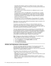
...use tab. 4. v Attention: These notices indicate potential damage to http://www.ibm.com/servers/eserver/support/xseries/index.html. 2. The actual procedure might be included on the IBM System x Documentation CD. Each caution and danger statement that appears in the multilingual Safety Information document, which damage could occur. 2 IBM System x3655 Type 7985...: Problem Determination and Service Guide The System x and xSeries Tools Center is on the IBM System x Documentation CD. These updates are made...
...use tab. 4. v Attention: These notices indicate potential damage to http://www.ibm.com/servers/eserver/support/xseries/index.html. 2. The actual procedure might be included on the IBM System x Documentation CD. Each caution and danger statement that appears in the multilingual Safety Information document, which damage could occur. 2 IBM System x3655 Type 7985...: Problem Determination and Service Guide The System x and xSeries Tools Center is on the IBM System x Documentation CD. These updates are made...
Service Guide
Page 22
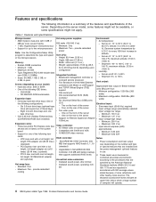
...: 10° to 35°C (50.0° to 914.4 m (3000 v Maximum: Two - Minimum: 100 V ac - These levels were measured in use. Features and specifications Microprocessor: v AMD Opteron dual-core with 2 MB (1 MB per hour: v Minimum configuration: 1230 Btu (360 watts) v Maximum configuration: ... 0.93 kVA RAID controller: Notes: v ServeRAID-8k-l SAS Controller, 256 1. Six 3.5-inch drive bays (optional tape drive will operate. 4 IBM System x3655 Type 7985: Problem Determination and Service Guide PCI Express riser card with SVGA and VGA v 16 MB DDR video memory - Maximum: 127 V ac v ...
...: 10° to 35°C (50.0° to 914.4 m (3000 v Maximum: Two - Minimum: 100 V ac - These levels were measured in use. Features and specifications Microprocessor: v AMD Opteron dual-core with 2 MB (1 MB per hour: v Minimum configuration: 1230 Btu (360 watts) v Maximum configuration: ... 0.93 kVA RAID controller: Notes: v ServeRAID-8k-l SAS Controller, 256 1. Six 3.5-inch drive bays (optional tape drive will operate. 4 IBM System x3655 Type 7985: Problem Determination and Service Guide PCI Express riser card with SVGA and VGA v 16 MB DDR video memory - Maximum: 127 V ac v ...
Service Guide
Page 24
... is in the server. When this LED is installed in use. To remove all electrical power from the server, you must disconnect the power cord from the rack. 6 IBM System x3655 Type 7985: Problem Determination and Service Guide If an optional IBM ServeRAID™ controller is flashing, it indicates that the server... is lit and not flashing, it indicates that the drive is turned on the light path diagnostics panel is no electrical power in use IBM Director to prevent the server from the DVD-ROM drive. When this LED is identifying the drive. The LED might be burned out...
... is in the server. When this LED is installed in use. To remove all electrical power from the server, you must disconnect the power cord from the rack. 6 IBM System x3655 Type 7985: Problem Determination and Service Guide If an optional IBM ServeRAID™ controller is flashing, it indicates that the server... is lit and not flashing, it indicates that the drive is turned on the light path diagnostics panel is no electrical power in use IBM Director to prevent the server from the DVD-ROM drive. When this LED is identifying the drive. The LED might be burned out...
Service Guide
Page 25
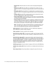
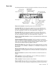
...power LEDs are lit. AC power LED: Each hot-swap power supply has an ac power LED and a dc power LED. System-management Ethernet connector: Use this connector. Ethernet link LEDs: When these LEDs are lit, they indicate that the server is transmitting to this connector. USB ... they indicate that the server is turned on page 142. DC power LED AC power LED Power cord connector Optional External SAS connector Systems-management Ethernet connector Ethernet activity LEDs Ethernet link LEDs Power supply 1 Serial connector Power-on the rear of LEDs, see "Power-supply ...
...power LEDs are lit. AC power LED: Each hot-swap power supply has an ac power LED and a dc power LED. System-management Ethernet connector: Use this connector. Ethernet link LEDs: When these LEDs are lit, they indicate that the server is transmitting to this connector. USB ... they indicate that the server is turned on page 142. DC power LED AC power LED Power cord connector Optional External SAS connector Systems-management Ethernet connector Ethernet activity LEDs Ethernet link LEDs Power supply 1 Serial connector Power-on the rear of LEDs, see "Power-supply ...
Service Guide
Page 26
...LED itself has failed. Internal connectors, LEDs, and jumpers The illustrations in this connector. System-error LED: When this LED is off, it indicates that ac power is lit, it indicates that a system error has occurred. An LED on the internal boards. Serial connector: Connect a 9-...is also lit to help isolate the error. The illustrations might differ slightly from your hardware. 8 IBM System x3655 Type 7985: Problem Determination and Service Guide still connected to visually locate the server among other servers. You can use IBM Director to light this LED to an ac power source...
...LED itself has failed. Internal connectors, LEDs, and jumpers The illustrations in this connector. System-error LED: When this LED is off, it indicates that ac power is lit, it indicates that a system error has occurred. An LED on the internal boards. Serial connector: Connect a 9-...is also lit to help isolate the error. The illustrations might differ slightly from your hardware. 8 IBM System x3655 Type 7985: Problem Determination and Service Guide still connected to visually locate the server among other servers. You can use IBM Director to light this LED to an ac power source...
Service Guide
Page 32
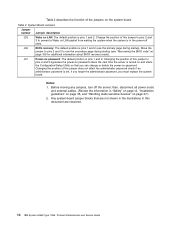
... password, you can change or delete the power-on the system board. Notes: 1. Any system-board jumper blocks that you must replace the system board. J35 BIOS recovery: The default position is pins 1 and 2 (use the secondary page during startup). J37 Power-on page 156...password. then, disconnect all power cords and external cables. (Review the information in this document are reserved. 14 IBM System x3655 Type 7985: Problem Determination and Service Guide System Board Jumpers Jumper number Jumper description J33 Wake on page 37.) 2. Table 2 describes the function of this ...
... password, you can change or delete the power-on the system board. Notes: 1. Any system-board jumper blocks that you must replace the system board. J35 BIOS recovery: The default position is pins 1 and 2 (use the secondary page during startup). J37 Power-on page 156...password. then, disconnect all power cords and external cables. (Review the information in this document are reserved. 14 IBM System x3655 Type 7985: Problem Determination and Service Guide System Board Jumpers Jumper number Jumper description J33 Wake on page 37.) 2. Table 2 describes the function of this ...
Service Guide
Page 35
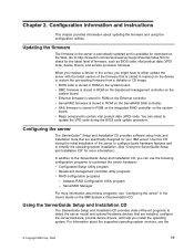
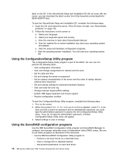
Go to http://www.ibm.com/servers/eserver/support/xseries/index.html to update the VPD code during the initial installation of the server to configure basic hardware features and to simplify the operating-system installation. (See "Using the ServerGuide Setup and ... Configuration/Setup Utility program v Baseboard management controller utility programs v RAID configuration programs - v BIOS code is stored in ROM on the IBM System x Documentation CD. v Major components contain vital product data (VPD) code. Chapter 2. ServeRAID Manager For more information.) In addition to...
Go to http://www.ibm.com/servers/eserver/support/xseries/index.html to update the VPD code during the initial installation of the server to configure basic hardware features and to simplify the operating-system installation. (See "Using the ServerGuide Setup and ... Configuration/Setup Utility program v Baseboard management controller utility programs v RAID configuration programs - v BIOS code is stored in ROM on the IBM System x Documentation CD. v Major components contain vital product data (VPD) code. Chapter 2. ServeRAID Manager For more information.) In addition to...
Service Guide
Page 36
... Turn on the screen to configure and manage redundant array of the BIOS. Select settings to learn about your language. Using the ServeRAID configuration programs Use the IBM ServeRAID Configuration Utility program and ServeRAID Manager to : a. If the CD does not start the Configuration/Setup Utility program... Set protocol parameters on password and an administrator password, you have set both a power-on hard disk drives 18 IBM System x3655 Type 7985: Problem Determination and Service Guide View the overview to view or change. You will appear. 3. If the ServerGuide...
... Turn on the screen to configure and manage redundant array of the BIOS. Select settings to learn about your language. Using the ServeRAID configuration programs Use the IBM ServeRAID Configuration Utility program and ServeRAID Manager to : a. If the CD does not start the Configuration/Setup Utility program... Set protocol parameters on password and an administrator password, you have set both a power-on hard disk drives 18 IBM System x3655 Type 7985: Problem Determination and Service Guide View the overview to view or change. You will appear. 3. If the ServerGuide...


