

Product Datasheet
Page 1
It is capable of recording a wide area of surveillance, and de-warping the native FishEye view in order to watch a stream that is a realtime, 360° situational awareness camera. Features IK10 Built in microphone. The ICIP360L4 series camera is undistorted to the human eye. ICIP-360L4 4 Megapixel Indoor, 360° Low Profile Network Dome Camera A 4.0 Megapixel 360° Indoor Dome camera with a built in Microphone PoE IC720 Platform Compatible
It is capable of recording a wide area of surveillance, and de-warping the native FishEye view in order to watch a stream that is a realtime, 360° situational awareness camera. Features IK10 Built in microphone. The ICIP360L4 series camera is undistorted to the human eye. ICIP-360L4 4 Megapixel Indoor, 360° Low Profile Network Dome Camera A 4.0 Megapixel 360° Indoor Dome camera with a built in Microphone PoE IC720 Platform Compatible

Product Datasheet
Page 2
ICIP-360L4 Specifications Model Image Sensor Effective Pixels Scanning System Electronic Shutter Speed Min. IR LEDs Length Day/Night Backlight Compensation White Balance Gain Control Noise Reduction Privacy Masking Focal Length Max Aperture Focus Control Angle of View Lens Type Mount Type Compression Resolution Frame Rate Bit Rate Compression Interface Ethernet Wi-Fi Protocol Compatibility Max. User Access Smart Phone ICIP-360L4 Camera 1/3" 4Megapixel progressive scan CMOS 2592(H)×1520(V) Progressive Auto/Manual 1/3(4)~1/10000 0.01lux/F2.0(color) ,0.001Lux...
ICIP-360L4 Specifications Model Image Sensor Effective Pixels Scanning System Electronic Shutter Speed Min. IR LEDs Length Day/Night Backlight Compensation White Balance Gain Control Noise Reduction Privacy Masking Focal Length Max Aperture Focus Control Angle of View Lens Type Mount Type Compression Resolution Frame Rate Bit Rate Compression Interface Ethernet Wi-Fi Protocol Compatibility Max. User Access Smart Phone ICIP-360L4 Camera 1/3" 4Megapixel progressive scan CMOS 2592(H)×1520(V) Progressive Auto/Manual 1/3(4)~1/10000 0.01lux/F2.0(color) ,0.001Lux...

Product Datasheet
Page 3
Memory Slot RS485 Alarm PIR Sensor Range Power Supply Power Consumption Working Environment Ingress Protection Vandal Resistance Dimensions (D×H) Weight Micro SD, Max 64GB N/A 1/1 channel In/Out N/A General 12VDC,PoE Max 6W -22°F ~ 140°F (-30°C ~ 60°C), Less than 95% RH N/A IK10 Φ4.33×2.13 (Φ110×54 mm) 0.55lbs (0.25kg)
Memory Slot RS485 Alarm PIR Sensor Range Power Supply Power Consumption Working Environment Ingress Protection Vandal Resistance Dimensions (D×H) Weight Micro SD, Max 64GB N/A 1/1 channel In/Out N/A General 12VDC,PoE Max 6W -22°F ~ 140°F (-30°C ~ 60°C), Less than 95% RH N/A IK10 Φ4.33×2.13 (Φ110×54 mm) 0.55lbs (0.25kg)

Product Datasheet
Page 4
All rights reserved ICIP-360L12 Optional Accessories MNT-IPMINIDOME-WALL MNT-PCNRIP MNT-JUNCTION BOX 2 MNT-POLIP IC Realtime LLC 3050 N Andrews Avenue Extension Pompano Beach, FL 33064 (866) 997-9009 www.icrealtime.com Designs and specifications subject to change without notice. Copyright © 2015 IC Realtime, LLC.
All rights reserved ICIP-360L12 Optional Accessories MNT-IPMINIDOME-WALL MNT-PCNRIP MNT-JUNCTION BOX 2 MNT-POLIP IC Realtime LLC 3050 N Andrews Avenue Extension Pompano Beach, FL 33064 (866) 997-9009 www.icrealtime.com Designs and specifications subject to change without notice. Copyright © 2015 IC Realtime, LLC.

Product Manual
Page 2
... standard factory packaging or material with strong electromagnetic radiation or unstable lighting. Please check if the power supply is rated 12V DC, DC5V or AC24V in case of CCD or CMOS. Please don't keep this series product! Welcome Thank you use this user's manual well for future reference! 1.Electrical safety All installation and operation here should conform to focus; This user's manual is...
... standard factory packaging or material with strong electromagnetic radiation or unstable lighting. Please check if the power supply is rated 12V DC, DC5V or AC24V in case of CCD or CMOS. Please don't keep this series product! Welcome Thank you use this user's manual well for future reference! 1.Electrical safety All installation and operation here should conform to focus; This user's manual is...
Product Manual
Page 3
...or more power supply modes for the device due to improve thunder proof effect. Operation and Daily Maintenance Please do not dismantle the device; The grounding holes of the product are not allowed during installation and use, please ...use oil-free cotton cloth or paper soaked with abrasiveness, otherwise it may cause damage to avoid scald. Warning Please use the standard accessories provided by manufacturer and make it dry, then use a dry cloth wetted by professional engineers. Please prevent the device surface from the lens center to change the cloth and wipe several times...
...or more power supply modes for the device due to improve thunder proof effect. Operation and Daily Maintenance Please do not dismantle the device; The grounding holes of the product are not allowed during installation and use, please ...use oil-free cotton cloth or paper soaked with abrasiveness, otherwise it may cause damage to avoid scald. Warning Please use the standard accessories provided by manufacturer and make it dry, then use a dry cloth wetted by professional engineers. Please prevent the device surface from the lens center to change the cloth and wipe several times...

Product Manual
Page 4
... value provided in the manual due to the product update; Please refer to the actual product for more details; The manual will be regularly upgraded according to the reasons such as the real environment is broken in the manual without prior announcement. Accessory Name Amount Network Camera 1 Quick Start Guide 1 Installation Accessories Bag 1 CD 1 iii Before installation, please open the package...
... value provided in the manual due to the product update; Please refer to the actual product for more details; The manual will be regularly upgraded according to the reasons such as the real environment is broken in the manual without prior announcement. Accessory Name Amount Network Camera 1 Quick Start Guide 1 Installation Accessories Bag 1 CD 1 iii Before installation, please open the package...

Product Manual
Page 5
Table of Contents 1 Structure ...1 1.1 Device External Cables 1 1.2 Dimensions 2 1.3 Bidirectional Talk 3 1.3.1 Device-end to PC-end 3 1.3.2 PC-end to Device-end 3 1.4 Alarm Setup 4 2 Installation ...5 2.1 Device Installation 5 2.2 Micro SD Card Installation 6 3 Quick Configuration Tool 8 3.1 Overview 8 3.2 Operation 8 4 Web Operation...10 4.1 Network Connection 10 4.2 Login and Main Interface 10 4.3 Panorama Function on Web 11 1 Appendix Toxic or Hazardous Materials or Elements 12 iv
Table of Contents 1 Structure ...1 1.1 Device External Cables 1 1.2 Dimensions 2 1.3 Bidirectional Talk 3 1.3.1 Device-end to PC-end 3 1.3.2 PC-end to Device-end 3 1.4 Alarm Setup 4 2 Installation ...5 2.1 Device Installation 5 2.2 Micro SD Card Installation 6 3 Quick Configuration Tool 8 3.1 Overview 8 3.2 Operation 8 4 Web Operation...10 4.1 Network Connection 10 4.2 Login and Main Interface 10 4.3 Panorama Function on Web 11 1 Appendix Toxic or Hazardous Materials or Elements 12 iv

Product Manual
Page 6
Sheet 1-1 1 Audio output port RCA Output audio signal to the actual products. Connect DC 12V power, input power. Audio port input RCA Input audio signal, receive analog audio signal from pick-up and other devices. please refer to Figure 1-1 or Figure 1-2 according to speaker and other devices. SN Port 1 LAN 2 POWER 3 AUDIO OUT 4 AUDIO IN 5 I /O port - I /O Port name Network port Power input port Connector Function Description Ethernet port Connect standard Ethernet cable. - 1 Structure 1.1 Device External Cables Note: There is slight...
Sheet 1-1 1 Audio output port RCA Output audio signal to the actual products. Connect DC 12V power, input power. Audio port input RCA Input audio signal, receive analog audio signal from pick-up and other devices. please refer to Figure 1-1 or Figure 1-2 according to speaker and other devices. SN Port 1 LAN 2 POWER 3 AUDIO OUT 4 AUDIO IN 5 I /O port - I /O Port name Network port Power input port Connector Function Description Ethernet port Connect standard Ethernet cable. - 1 Structure 1.1 Device External Cables Note: There is slight...
Product Manual
Page 7
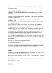
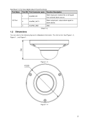
I/O Port 2 ALARM_OUT1 Alarm output port, output alarm signal to alarm device. 3 ALARM_GND GND Sheet 1-2 1.2 Dimensions You can refer to the following figures for more details about I/O port functions. See Figure 1- 3, Figure 1- , and Figure 1- . Figure 1- 3 Figure 1- 4 2 The Unit is mm. Port Name Port SN Port Connector name Function Description 1 ALARM_IN1 Alarm input port, receive the on-off signal from external alarm source. See Sheet 1-2 for dimension information.
I/O Port 2 ALARM_OUT1 Alarm output port, output alarm signal to alarm device. 3 ALARM_GND GND Sheet 1-2 1.2 Dimensions You can refer to the following figures for more details about I/O port functions. See Figure 1- 3, Figure 1- , and Figure 1- . Figure 1- 3 Figure 1- 4 2 The Unit is mm. Port Name Port SN Port Connector name Function Description 1 ALARM_IN1 Alarm input port, receive the on-off signal from external alarm source. See Sheet 1-2 for dimension information.
Product Manual
Page 8
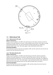
... audio input port of the PC, and then connect the earphone to stop the bidirectional talk function. Click "Talk" button again to the audio output port of the PC. Click "Talk" button again to enable the bidirectional talk function. You can 't be used at the device-end. 3 Login the Web and then click the "Talk" button to stop the bidirectional talk function. Listening Operation...
... audio input port of the PC, and then connect the earphone to stop the bidirectional talk function. Click "Talk" button again to the audio output port of the PC. Click "Talk" button again to enable the bidirectional talk function. You can 't be used at the device-end. 3 Login the Web and then click the "Talk" button to stop the bidirectional talk function. Listening Operation...
Product Manual
Page 9
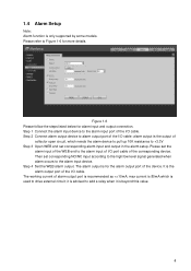
... to +3.3V Step 3 Open WEB and set corresponding alarm input and output in the alarm setup. Step 4 Set the WEB alarm output. alarm output is the output of collector open circuit, which needs the alarm device to pull up 10K resistance to alarm output port of the I /O cable; Step 1 Connect the alarm input device to Figure 1-6 for alarm input and output connection. Please refer to the alarm input port of the I /O cable. The alarm output is only supported by some models.
... to +3.3V Step 3 Open WEB and set corresponding alarm input and output in the alarm setup. Step 4 Set the WEB alarm output. alarm output is the output of collector open circuit, which needs the alarm device to pull up 10K resistance to alarm output port of the I /O cable; Step 1 Connect the alarm input device to Figure 1-6 for alarm input and output connection. Please refer to the alarm input port of the I /O cable. The alarm output is only supported by some models.
Product Manual
Page 10
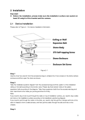
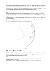
... installation positioning diagram. Note: If you need to dig a hole to pull through the side exit hole on top of the bracket and the camera. 2.1 Device Installation Please refer to Figure 2- 1 for device installation information. Figure 2- 1 Step 1 Use the inner hex wrench from the accessories bag to unfasten the 3 hex screws on the installation ceiling or the wall according to form a cable access...
... installation positioning diagram. Note: If you need to dig a hole to pull through the side exit hole on top of the bracket and the camera. 2.1 Device Installation Please refer to Figure 2- 1 for device installation information. Figure 2- 1 Step 1 Use the inner hex wrench from the accessories bag to unfasten the 3 hex screws on the installation ceiling or the wall according to form a cable access...
Product Manual
Page 11
... the dome protection enclosure; So far installation is M3. Note: Please make sure the wire connection between power panel and device motherboard is firm, otherwise may improve device reliability. Make "TOP" direction of the chassis and the GND screw is completed. Note: Please refer to Micro SD card installation steps if you need to install Micro SD card, and operate step...
... the dome protection enclosure; So far installation is M3. Note: Please make sure the wire connection between power panel and device motherboard is firm, otherwise may improve device reliability. Make "TOP" direction of the chassis and the GND screw is completed. Note: Please refer to Micro SD card installation steps if you need to install Micro SD card, and operate step...

Product Manual
Page 13
... to login, other setups are using device background upgrade port 3800 to the IP addresses in Web Network interface. In the device list interface, you can view device IP address, port number, subnet mask, default gateway, MAC address and etc. In Figure 3-2, you can view device IP address, user name, password and port. Please note the port information here shall be identical with the port value you cannot login the device. 3 Quick Configuration Tool 3.1 Overview Quick configuration...
... to login, other setups are using device background upgrade port 3800 to the IP addresses in Web Network interface. In the device list interface, you can view device IP address, port number, subnet mask, default gateway, MAC address and etc. In Figure 3-2, you can view device IP address, user name, password and port. Please note the port information here shall be identical with the port value you cannot login the device. 3 Quick Configuration Tool 3.1 Overview Quick configuration...

Product Manual
Page 14
See Figure 3- . Figure 3- 1 After you logged in the resources CD. 9 Figure 3- 3 For detailed information and operation instruction of the quick configuration tool, please refer to the Quick Configuration Tool User's Manual included in , the configuration tool main interface is shown as below.
See Figure 3- . Figure 3- 1 After you logged in the resources CD. 9 Figure 3- 3 For detailed information and operation instruction of the quick configuration tool, please refer to the Quick Configuration Tool User's Manual included in , the configuration tool main interface is shown as below.

Product Manual
Page 15
....168.1.108, then please input http:// 192.168.1.108 in the address bar. For example, if your user name and password. Please input your camera IP is 255.255.255.0. Web includes several modules: Monitor channel preview, system configuration, alarm and etc. 4.1 Network Connection Please follow the steps listed below . After you first login. 4 Web Operation This series network camera products support the Web access and management via PC.
....168.1.108, then please input http:// 192.168.1.108 in the address bar. For example, if your user name and password. Please input your camera IP is 255.255.255.0. Web includes several modules: Monitor channel preview, system configuration, alarm and etc. 4.1 Network Connection Please follow the steps listed below . After you first login. 4 Web Operation This series network camera products support the Web access and management via PC.

Product Manual
Page 16
Otherwise, abnormity may happen to the exact installation way. Please configure corresponding installation mode on Web There is a panorama icon at the lower-left corner of web interface and you can click it to view installation mode and display mode at the right. Figure 4-2 Please refer to the Web Operation Manual included in the resource CD for detailed operation instruction. 4.3 Panorama Function on the WEB config page according to the video display. 11
Otherwise, abnormity may happen to the exact installation way. Please configure corresponding installation mode on Web There is a panorama icon at the lower-left corner of web interface and you can click it to view installation mode and display mode at the right. Figure 4-2 Please refer to the Web Operation Manual included in the resource CD for detailed operation instruction. 4.3 Panorama Function on the WEB config page according to the video display. 11

Product Manual
Page 17
...user interface. All the designs and software here are subject to change without prior written notice. All trademarks and registered trademarks mentioned are the properties of their respective owners... or mutate so that the use of these (substances or elements...the parts is below the relevant threshold of the SJ/T11363-2006 standard. Note This user's manual ...9675; ○ ○ Cr VI ○ ○ PBB ○ ○ PBDE ○ ○ Wire and Cable ○ ○ ○ ○ ○ ○ Packing Components ○ ○ ○ &#...
...user interface. All the designs and software here are subject to change without prior written notice. All trademarks and registered trademarks mentioned are the properties of their respective owners... or mutate so that the use of these (substances or elements...the parts is below the relevant threshold of the SJ/T11363-2006 standard. Note This user's manual ...9675; ○ ○ Cr VI ○ ○ PBB ○ ○ PBDE ○ ○ Wire and Cable ○ ○ ○ ○ ○ ○ Packing Components ○ ○ ○ &#...


