

Product Manual
Page 2
... repair. 2.Environment Please don't aim the device at the same time; This user's manual is wet, dusty, extremely hot, and extremely cold and with same quality when transporting the device. Please read the following safeguard and warnings carefully before you for emergent power off before operating the device. Please check if the power supply is correct before installing wiring...
... repair. 2.Environment Please don't aim the device at the same time; This user's manual is wet, dusty, extremely hot, and extremely cold and with same quality when transporting the device. Please read the following safeguard and warnings carefully before you for emergent power off before operating the device. Please check if the power supply is correct before installing wiring...

Product Manual
Page 3
... to change the cloth and wipe several times if it to clean the device. Do not touch the CCD (CMOS) optic component directly. If there is just for more power supply modes for the device due to unprofessional dismantling. Warning Please use oil-free cotton cloth or paper soaked with alcohol or detergent to clean the device. the manual...
... to change the cloth and wipe several times if it to clean the device. Do not touch the CCD (CMOS) optic component directly. If there is just for more power supply modes for the device due to unprofessional dismantling. Warning Please use oil-free cotton cloth or paper soaked with alcohol or detergent to clean the device. the manual...

Product Manual
Page 4
Before installation, please open the package and check all the components are included. Accessory Name Network Camera Unit Quick Start Guide Installation Accessories Bag CD Amount 1 1 1 1 iii Please refer to the disk for more details, check and download corresponding user's manual and tool. Contact your local retailer ASAP if something is broken in your package.
Before installation, please open the package and check all the components are included. Accessory Name Network Camera Unit Quick Start Guide Installation Accessories Bag CD Amount 1 1 1 1 iii Please refer to the disk for more details, check and download corresponding user's manual and tool. Contact your local retailer ASAP if something is broken in your package.

Product Manual
Page 6
See Figure1-2. Component Component Name 1 Dome module 2 Dome enclosure Port Sheet 1-1 Port Name Port 3 Network port Port 4 Power port Sheet 1-2 1.2 Framework and Dimension The figures are used to know the components and cable port function. There are differences about structure components and cables between different models, please refer to the actual object for reference only, which is used to know the device dimension. Figure 1-1 Component structure Please refer to...
See Figure1-2. Component Component Name 1 Dome module 2 Dome enclosure Port Sheet 1-1 Port Name Port 3 Network port Port 4 Power port Sheet 1-2 1.2 Framework and Dimension The figures are used to know the components and cable port function. There are differences about structure components and cables between different models, please refer to the actual object for reference only, which is used to know the device dimension. Figure 1-1 Component structure Please refer to...

Product Manual
Page 7
... "0". 2 When there is idle, the device collects the logic "1". Figure1-2 1.3 Alarm Setup Note: Only supported by some series products. Step 4 Set the WEB alarm output. See Figure 1-4. Alarm input on device. When the input signal is collector open circuit output which connects 10K resistor to the following figure for the alarm output port of the alarm input port. Figure1-3 Alarm input, output description: Step 1 Connect alarm input device to the...
... "0". 2 When there is idle, the device collects the logic "1". Figure1-2 1.3 Alarm Setup Note: Only supported by some series products. Step 4 Set the WEB alarm output. See Figure 1-4. Alarm input on device. When the input signal is collector open circuit output which connects 10K resistor to the following figure for the alarm output port of the alarm input port. Figure1-3 Alarm input, output description: Step 1 Connect alarm input device to the...

Product Manual
Page 8
The working current of output signal is alarm output. After external pull-up resistance externally to low level when there is high level, and it needs to increase pull-up resistance is increased, the default of alarm output port is high and low level. See Figure 1-5 When alarm output is OC, it switches to work normally; Figure 1-4 Please refer to the following figure for alarm output information. output signal is recommended as
The working current of output signal is alarm output. After external pull-up resistance externally to low level when there is high level, and it needs to increase pull-up resistance is increased, the default of alarm output port is high and low level. See Figure 1-5 When alarm output is OC, it switches to work normally; Figure 1-4 Please refer to the following figure for alarm output information. output signal is recommended as

Product Manual
Page 9
Secure these three bolts firmly. Note: If user pulls out cable from top of the camera and the bracket. Figure 2-1 Device installation illustration Step 1 Use inner hex wrench in the accessories bag, and then paste it on the ceiling or the wall according to your monitor area requirements. Step 2 Please take out the installation position map in the accessories bag to...
Secure these three bolts firmly. Note: If user pulls out cable from top of the camera and the bracket. Figure 2-1 Device installation illustration Step 1 Use inner hex wrench in the accessories bag, and then paste it on the ceiling or the wall according to your monitor area requirements. Step 2 Please take out the installation position map in the accessories bag to...

Product Manual
Page 10
..., rotate the bracket horizontally, and adjust lens horizontal direction to the three plastic expansion bolt holes in the installation position. Figure 2-2 Note: Long press the "Reset button" shown in Figure 2-3 for 10 seconds when the device is power on if the device needs to restore to factory setting. If the device needs to use WPS function, please short press the "Reset button" shown in...
..., rotate the bracket horizontally, and adjust lens horizontal direction to the three plastic expansion bolt holes in the installation position. Figure 2-2 Note: Long press the "Reset button" shown in Figure 2-3 for 10 seconds when the device is power on if the device needs to restore to factory setting. If the device needs to use WPS function, please short press the "Reset button" shown in...

Product Manual
Page 11
... in figure 2-2; Please shut down the power and then turn off the device before you install the Micro SD card. Figure 2-3 Micro SD Card installation illustration 1 Figure 2-4 Micro SD Card installation illustration 2 6 open the Micro SD Card slot according to the following chapter. 2.2 Micro SD Card Installation Note: Some series products do not support the Micro SD card function, which can't be applied to...
... in figure 2-2; Please shut down the power and then turn off the device before you install the Micro SD card. Figure 2-3 Micro SD Card installation illustration 1 Figure 2-4 Micro SD Card installation illustration 2 6 open the Micro SD Card slot according to the following chapter. 2.2 Micro SD Card Installation Note: Some series products do not support the Micro SD card function, which can't be applied to...
Product Manual
Page 12
... the quick configuration tool. See Figure 3-1 for more details. 7 In this chapter, it needs to connect wired network to the document in the network parameters of the WEB interface, please refer to configure wireless parameters before using wireless network cameras. Enter the IP address, user name, password and port number of the camera, and click "Confirm". Note: The default user name and password are admin and admin respectively, the default of port is the same when leaving factory (default...
... the quick configuration tool. See Figure 3-1 for more details. 7 In this chapter, it needs to connect wired network to the document in the network parameters of the WEB interface, please refer to configure wireless parameters before using wireless network cameras. Enter the IP address, user name, password and port number of the camera, and click "Confirm". Note: The default user name and password are admin and admin respectively, the default of port is the same when leaving factory (default...

Product Manual
Page 13
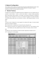
... disk and the actual interface for more details. Figure 3-2 3.2 Login WEB Interface Note: Different devices may have different WEB interfaces, the figures below , please input your user name and password (Default user name is admin and password is admin respectively), click "login". See Figure 3-2 for more details. 8 Figure 3-1 Step 3 Modify the camera IP address on the "Net" interface, click "Save" to the document...
... disk and the actual interface for more details. Figure 3-2 3.2 Login WEB Interface Note: Different devices may have different WEB interfaces, the figures below , please input your user name and password (Default user name is admin and password is admin respectively), click "login". See Figure 3-2 for more details. 8 Figure 3-1 Step 3 Modify the camera IP address on the "Net" interface, click "Save" to the document...

Product Manual
Page 14
see Figure 3-4 for the WEB main interface. Please modify the administrator password as soon as possible after you successfully logged in. Figure 3-3 Step 3 Install controls according to the system prompt; Figure 3-4 9
see Figure 3-4 for the WEB main interface. Please modify the administrator password as soon as possible after you successfully logged in. Figure 3-3 Step 3 Install controls according to the system prompt; Figure 3-4 9

Product Manual
Page 15
Slight difference may be found in user interface. All the designs and software here are subject to change without prior written notice. All trademarks and registered trademarks mentioned are the properties of their respective owners. If there is for more information. 10 Note: This quick start guide is any uncertainty or controversy, please refer to the final explanation of us. Please visit our website or contact your local service engineer for reference only.
Slight difference may be found in user interface. All the designs and software here are subject to change without prior written notice. All trademarks and registered trademarks mentioned are the properties of their respective owners. If there is for more information. 10 Note: This quick start guide is any uncertainty or controversy, please refer to the final explanation of us. Please visit our website or contact your local service engineer for reference only.

Product Datasheet
Page 2
... Max IR LEDs Length Day/Night Backlight Compensation White Balance Gain Control Noise Reduction Privacy Masking Focal Length Max Aperture Focus Control Angle of View Lens Type Mount Type Compression Resolution Frame Rate Bit Rate Corridor Mode Smart Detection Ethernet Protocol Compatibility Max. ICIP-D2001-IR-D-2.8 Specifications Model Image Sensor Effective Pixels Scanning system Electronic Shutter Speed Min. User Access Smart Phone Power Supply Power Consumption ICIP-D2001-IR-D-2.8 Camera 1/2.7" 2MP progressive scan CMOS 1920 (H)×1080 (V) Progressive Auto/Manual 1/3(4) ~ 1/10000...
... Max IR LEDs Length Day/Night Backlight Compensation White Balance Gain Control Noise Reduction Privacy Masking Focal Length Max Aperture Focus Control Angle of View Lens Type Mount Type Compression Resolution Frame Rate Bit Rate Corridor Mode Smart Detection Ethernet Protocol Compatibility Max. ICIP-D2001-IR-D-2.8 Specifications Model Image Sensor Effective Pixels Scanning system Electronic Shutter Speed Min. User Access Smart Phone Power Supply Power Consumption ICIP-D2001-IR-D-2.8 Camera 1/2.7" 2MP progressive scan CMOS 1920 (H)×1080 (V) Progressive Auto/Manual 1/3(4) ~ 1/10000...

Product Datasheet
Page 3
Copyright © 2015 IC Realtime, LLC. All rights reserved. Less than 90% RH IP67 IK10 Φ4.33"×3.19"mm/Φ110mm×81mm 0.73lb/0.33kg MNT-IPMINIDOME-WALL MNT-JUNCTION BOX 2 MNT-PCNRIP MNT-POLIP IC Realtime LLC 3050 N Andrews Avenue Extension Pompano Beach, FL 33064 (866) 997-9009 www.icrealtime.com Designs and specifications subject to change without notice. Working Environment Ingress Protection Vandal Resistance Dimensions Weight Accessories -4°F ~ 140°F/-20°C ~ 60°C;
Copyright © 2015 IC Realtime, LLC. All rights reserved. Less than 90% RH IP67 IK10 Φ4.33"×3.19"mm/Φ110mm×81mm 0.73lb/0.33kg MNT-IPMINIDOME-WALL MNT-JUNCTION BOX 2 MNT-PCNRIP MNT-POLIP IC Realtime LLC 3050 N Andrews Avenue Extension Pompano Beach, FL 33064 (866) 997-9009 www.icrealtime.com Designs and specifications subject to change without notice. Working Environment Ingress Protection Vandal Resistance Dimensions Weight Accessories -4°F ~ 140°F/-20°C ~ 60°C;


