Product Datasheet
Page 1
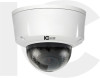
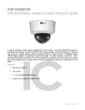
... Motorized Varifocal Lens Supports PoE, Alarm I /O's, and support for viewing up to 60' with an audio input for external microphones, alarm I /O's & Built-in Mic Revision 1.2; 09/2015 the ICIP-D3000VIR. This camera also comes equipped with 0 light. Featuring a hardened dome chassis, the ICIP-D3000VIR is a high resolution 3 Megapixel Aptina CMOS imager, capable of outputting a crystal clear image. ICIP-D3000VIR 3 MP Indoor/Outdoor, Vandalproof Full-Size IR Dome IP Camera A rugged, day/night, outdoor rated 3 Megapixel IP dome camera -
... Motorized Varifocal Lens Supports PoE, Alarm I /O's, and support for viewing up to 60' with an audio input for external microphones, alarm I /O's & Built-in Mic Revision 1.2; 09/2015 the ICIP-D3000VIR. This camera also comes equipped with 0 light. Featuring a hardened dome chassis, the ICIP-D3000VIR is a high resolution 3 Megapixel Aptina CMOS imager, capable of outputting a crystal clear image. ICIP-D3000VIR 3 MP Indoor/Outdoor, Vandalproof Full-Size IR Dome IP Camera A rugged, day/night, outdoor rated 3 Megapixel IP dome camera -

Product Datasheet
Page 2
... Network RJ-45 (10/100Base-T) IPv4/IPv6, HTTP, HTTPS, SSL, TCP/IP, UDP, UPnP, ICMP, IGMP, SNMP, RTSP, RTP, SMTP, NTP, DHCP, DNS, PPPOE, DDNS, FTP, IP Filter, QoS, Bonjour ONVIF, CGI 20 users iPhone, iPad, Android, Windows Phone Auxiliary Interface Micro SD, Max 64GB 1/1 channel In/Out User Access Smart Phone Memory Slot Alarm ICIP-D3000VIR Camera 1/3" 3Megapixel Aptina CMOS 2048(H)×1536(V) Progressive Auto/Manual 1/3 ~ 1/10000 Color...
... Network RJ-45 (10/100Base-T) IPv4/IPv6, HTTP, HTTPS, SSL, TCP/IP, UDP, UPnP, ICMP, IGMP, SNMP, RTSP, RTP, SMTP, NTP, DHCP, DNS, PPPOE, DDNS, FTP, IP Filter, QoS, Bonjour ONVIF, CGI 20 users iPhone, iPad, Android, Windows Phone Auxiliary Interface Micro SD, Max 64GB 1/1 channel In/Out User Access Smart Phone Memory Slot Alarm ICIP-D3000VIR Camera 1/3" 3Megapixel Aptina CMOS 2048(H)×1536(V) Progressive Auto/Manual 1/3 ~ 1/10000 Color...
Product Manual
Page 1
HD (IR) Vandal Proof Network Dome Camera User's Manual Version 1.6.0
HD (IR) Vandal Proof Network Dome Camera User's Manual Version 1.6.0

Product Manual
Page 3
... time; Do not allow the water and other liquid falling into the camera. We are recommended to be grounded to better prevent thunder. Always follow the instruction guide the manufacturer recommended. 4.Qualified engineers needed All the examination and repair work . Daily Maintenance Please shut down the device and then unplug the power cable before completing installation. Please install the proper power...
... time; Do not allow the water and other liquid falling into the camera. We are recommended to be grounded to better prevent thunder. Always follow the instruction guide the manufacturer recommended. 4.Qualified engineers needed All the examination and repair work . Daily Maintenance Please shut down the device and then unplug the power cable before completing installation. Please install the proper power...

Product Manual
Page 5
...1.2 Features...1 1.3 Specifications ...2 1.3.1 Performance...2 2 Structure ...5 2.1 Dimensions...5 2.2 Port Description ...5 2.3 Bidirectional talk...11 2.3.1 Device-end to PC-end 11 2.3.2 PC-end to the Device-end 11 2.4 Alarm Setup...12 3 Installation...14 3.1 Device Installation Introduction 14 3.2 Device Installation Steps 14 3.2.1 Manual Zoom Lens Focus Operation 18 3.2.2 Side Cable Exit ...19 3.2.3 Cable Connection 19 3.3 Micro SD Card Installation 21 4 Quick Configuration Tool...22 4.1 Overview ...22 4.2 Operation ...22 5 Web Operation...24 5.1 Network Connection 24 5.2 Login and...
...1.2 Features...1 1.3 Specifications ...2 1.3.1 Performance...2 2 Structure ...5 2.1 Dimensions...5 2.2 Port Description ...5 2.3 Bidirectional talk...11 2.3.1 Device-end to PC-end 11 2.3.2 PC-end to the Device-end 11 2.4 Alarm Setup...12 3 Installation...14 3.1 Device Installation Introduction 14 3.2 Device Installation Steps 14 3.2.1 Manual Zoom Lens Focus Operation 18 3.2.2 Side Cable Exit ...19 3.2.3 Cable Connection 19 3.3 Micro SD Card Installation 21 4 Quick Configuration Tool...22 4.1 Overview ...22 4.2 Operation ...22 5 Web Operation...24 5.1 Network Connection 24 5.2 Login and...

Product Manual
Page 6
... network camera configuration and management via Ethernet. Support device management via the sound or the light. 1 General Introduction 1.1 Overview This series network camera integrates the traditional camera and network video technology. This series network camera uses standard H.264 and MJPEG video compression technology and G.711a audio compression technology, which can connect to pre-record audio file) Function Real-time video detect: motion detect, tampering. Can generate an alarm when network abnormal, Micro SD card abnormal event occurred...
... network camera configuration and management via Ethernet. Support device management via the sound or the light. 1 General Introduction 1.1 Overview This series network camera integrates the traditional camera and network video technology. This series network camera uses standard H.264 and MJPEG video compression technology and G.711a audio compression technology, which can connect to pre-record audio file) Function Real-time video detect: motion detect, tampering. Can generate an alarm when network abnormal, Micro SD card abnormal event occurred...

Product Manual
Page 7
... gain setup. Support video watermark function to avoid vicious video modification. 1.3 Specifications 1.3.1 Performance Please refer to 1/100000. Auto Iris DC drive Gain Control Manual/Auto Video Parameter White Balance BLC Electronic Shutter Motorized Focus Video Compression Standard Manual/Auto On/Off Manual/Auto PAL:It ranges from 1/4 to the following sheet for network camera performance specification. Image Sensor 1/3-inch CMOS Pixel 2048(H)×1536(V) Day/Night Mode Support day/night mode switch...
... gain setup. Support video watermark function to avoid vicious video modification. 1.3 Specifications 1.3.1 Performance Please refer to 1/100000. Auto Iris DC drive Gain Control Manual/Auto Video Parameter White Balance BLC Electronic Shutter Motorized Focus Video Compression Standard Manual/Auto On/Off Manual/Auto PAL:It ranges from 1/4 to the following sheet for network camera performance specification. Image Sensor 1/3-inch CMOS Pixel 2048(H)×1536(V) Day/Night Mode Support day/night mode switch...

Product Manual
Page 8
...Motion Detect Video Loss Alarm Input Record Priority Storage Management Wire Network Network Protocol Remote Operation Protocol Video Output Reset Note: Extra stream 2's actual frame rate depends on device max capacity set which can be adjusted within its range. Max 1f/s snapshot. It is JPEG. Activation event, alarm device, audio/video storage, image snapshot, log, email function and etc. 1-channel input,1-channel output Manual>External alarm >Video detect>Schedule Support Micro SD card storage, NAS storage 1-channel wire Ethernet port, 10/100 Base-T Ethernet HTTP,TCP,ARP,RTSP...
...Motion Detect Video Loss Alarm Input Record Priority Storage Management Wire Network Network Protocol Remote Operation Protocol Video Output Reset Note: Extra stream 2's actual frame rate depends on device max capacity set which can be adjusted within its range. Max 1f/s snapshot. It is JPEG. Activation event, alarm device, audio/video storage, image snapshot, log, email function and etc. 1-channel input,1-channel output Manual>External alarm >Video detect>Schedule Support Micro SD card storage, NAS storage 1-channel wire Ethernet port, 10/100 Base-T Ethernet HTTP,TCP,ARP,RTSP...

Product Manual
Page 15
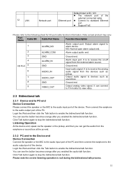
... port network Ethernet port Network cable port. 5 I/O I/O port / It includes alarm input/output, audio and analog output. 6 RESET Reset button / Reset button. light Connect to fan to AC 24V power. It is optional. 10 Micro SD Micro SD card Micro slot entry card SD Connect to Micro SD card to restore factory default setup. SN Port Port Name Connector Function Description 1 POWER AC 24V port power / 2 POWER DC 12V port power / Cable exit of view and 7 AUTO FOCUS 5-direction button / definition. Connect to the following sheet for external connection...
... port network Ethernet port Network cable port. 5 I/O I/O port / It includes alarm input/output, audio and analog output. 6 RESET Reset button / Reset button. light Connect to fan to AC 24V power. It is optional. 10 Micro SD Micro SD card Micro slot entry card SD Connect to Micro SD card to restore factory default setup. SN Port Port Name Connector Function Description 1 POWER AC 24V port power / 2 POWER DC 12V port power / Cable exit of view and 7 AUTO FOCUS 5-direction button / definition. Connect to the following sheet for external connection...
Product Manual
Page 16
... Device Connection Connect the speaker or the MIC to the audio input port of the PC and then connect the earphone to standard Ethernet port. Support PoE. 12 LAN Network port Ethernet port Default input is DC 12V. The network port of the external connected cable. Connect to the audio output port of the device. Please refer to the following sheet for I /O Port 5 6 7 8 ALARM_IN GND AUDIO_IN AUDIO_OUT GND Alarm input port.
... Device Connection Connect the speaker or the MIC to the audio input port of the PC and then connect the earphone to standard Ethernet port. Support PoE. 12 LAN Network port Ethernet port Default input is DC 12V. The network port of the external connected cable. Connect to the audio output port of the device. Please refer to the following sheet for I /O Port 5 6 7 8 ALARM_IN GND AUDIO_IN AUDIO_OUT GND Alarm input port.
Product Manual
Page 17
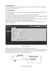
....) 4) Set the WEB alarm output. When the input signal is for the first channel of the I/O cable. Please set the alarm input 01 port for the alarm output port of the I /O cable (No.4 pin). See Figure 2-13. When the input signal is shown as in Figure 2-12. Then you can get the audio from the earphone or sound box at the device-end. 2.4 Alarm Setup The alarm...
....) 4) Set the WEB alarm output. When the input signal is for the first channel of the I/O cable. Please set the alarm input 01 port for the alarm output port of the I /O cable (No.4 pin). See Figure 2-13. When the input signal is shown as in Figure 2-12. Then you can get the audio from the earphone or sound box at the device-end. 2.4 Alarm Setup The alarm...
Product Manual
Page 20
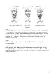
... Motorized Zoom Lens Series Non-IR Series IR Manual Zoom Series Figure 3-2 Step 1 Take the installation position map from the accessories bag and then paste it . If you need to dig a hole to pull through the cable, you just dug and then fix firmly. Step 3 Please remove the device cable (Provided) network port and the power terminal. Then please follow the prompt on the dome camera enclosure...
... Motorized Zoom Lens Series Non-IR Series IR Manual Zoom Series Figure 3-2 Step 1 Take the installation position map from the accessories bag and then paste it . If you need to dig a hole to pull through the cable, you just dug and then fix firmly. Step 3 Please remove the device cable (Provided) network port and the power terminal. Then please follow the prompt on the dome camera enclosure...
Product Manual
Page 21
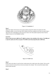
... specification is secure on the installation surface. Take three ST3.0 self-tapping screws and secure them in Step 1. Important Please earth the device GND hole (GND) to the metal hooks of the rear panel. The GND port is near the cable exit of the chassis. Then connect the network cable and the power ...terminal. Figure 3-4 GND hole Step 5 Please refer to the Step 3 to put the driver module back to enhance the reliability of the installation surface. ...
... specification is secure on the installation surface. Take three ST3.0 self-tapping screws and secure them in Step 1. Important Please earth the device GND hole (GND) to the metal hooks of the rear panel. The GND port is near the cable exit of the chassis. Then connect the network cable and the power ...terminal. Figure 3-4 GND hole Step 5 Please refer to the Step 3 to put the driver module back to enhance the reliability of the installation surface. ...
Product Manual
Page 23
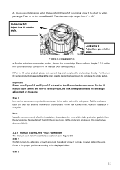
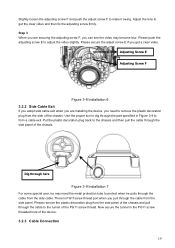
... refer to adjust the video pan angle. d). Image pan rotation angle setup. Please refer to Figure 3-7 to turn lock screw D to chapter 3.2.1 for the lens zoom and focus operation of the protection enclosure. Lock screw B/C Adjust lens tilt rotation angle. Figure 3-7 Installation 5 e) For the motorized zoom series product, please skip current step. Step 7 Line up the dome camera protection enclosure to make it swing. Now the installation is based on the...
... refer to adjust the video pan angle. d). Image pan rotation angle setup. Please refer to Figure 3-7 to turn lock screw D to chapter 3.2.1 for the lens zoom and focus operation of the protection enclosure. Lock screw B/C Adjust lens tilt rotation angle. Figure 3-7 Installation 5 e) For the motorized zoom series product, please skip current step. Step 7 Line up the dome camera protection enclosure to make it swing. Now the installation is based on the...
Product Manual
Page 24
... here Figure 3-9 Installation 7 For some special user, he may become blur. Please secure the adjust screw E if you can see the video may need to the chassis and then pull the cable through the part specified in the PG11 screw threaded hole of the chassis. Now secure the tunnel in Figure 3-9 to get a clear video. Adjust the lens to form a cable exit. Dig...
... here Figure 3-9 Installation 7 For some special user, he may become blur. Please secure the adjust screw E if you can see the video may need to the chassis and then pull the cable through the part specified in the PG11 screw threaded hole of the chassis. Now secure the tunnel in Figure 3-9 to get a clear video. Adjust the lens to form a cable exit. Dig...
Product Manual
Page 27
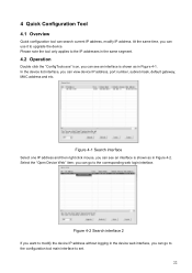
... applies to the corresponding web login interface. Figure 4-1 Search interface Select one IP address and then right click mouse, you can see an interface is shown as in Figure 4-2. you can go to the configuration tool main interface to upgrade the device. 4 Quick Configuration Tool 4.1 Overview Quick configuration tool can view device IP address, port number, subnet mask, default gateway, MAC address and etc. Select the...
... applies to the corresponding web login interface. Figure 4-1 Search interface Select one IP address and then right click mouse, you can see an interface is shown as in Figure 4-2. you can go to the configuration tool main interface to upgrade the device. 4 Quick Configuration Tool 4.1 Overview Quick configuration tool can view device IP address, port number, subnet mask, default gateway, MAC address and etc. Select the...

Product Manual
Page 28
... operation instruction of the quick configuration tool, please refer to the login interface. In the configuration tool search interface (Figure 4-1), please select a device IP address and then double click it to login. If you set in TCP port in Web Network interface. Figure 4-3 Login prompt After you can select an IP address and then click the Login button to go to the Quick Configuration Tool User's Manual included in , the configuration...
... operation instruction of the quick configuration tool, please refer to the login interface. In the configuration tool search interface (Figure 4-1), please select a device IP address and then double click it to login. If you set in TCP port in Web Network interface. Figure 4-3 Login prompt After you can select an IP address and then click the Login button to go to the Quick Configuration Tool User's Manual included in , the configuration...

Product Manual
Page 29
...: Monitor channel preview, system configuration, alarm and etc. 5.1 Network Connection Please follow the steps listed below . See Figure 5- 2. 5 Web Operation This series network camera products support the Web access and management via PC. Please input your password after you first login. 24 See Figure 5- 1. Note: For security reasons, please modify your user name and password. Gateway is 192.168.1.1 Use order ping network camera address) to the network properly. Please set the...
...: Monitor channel preview, system configuration, alarm and etc. 5.1 Network Connection Please follow the steps listed below . See Figure 5- 2. 5 Web Operation This series network camera products support the Web access and management via PC. Please input your password after you first login. 24 See Figure 5- 1. Note: For security reasons, please modify your user name and password. Gateway is 192.168.1.1 Use order ping network camera address) to the network properly. Please set the...

Product Manual
Page 30
See Figure 5- 3. Please refer to the Web Operation Manual included in unit. Figure 5- 3 Web monitoring window 25 Figure 5- 2 Web login After you successfully logged in, please install WEB plug-in the resource CD for detailed operation instruction.
See Figure 5- 3. Please refer to the Web Operation Manual included in unit. Figure 5- 3 Web monitoring window 25 Figure 5- 2 Web login After you successfully logged in, please install WEB plug-in the resource CD for detailed operation instruction.

Product Manual
Page 31
... view the clear video when the IR light is 0, disk as the storage media to storage the write times schedule record file. I can not boot up the device. Audio function Please use port 3800 to restore factory default setup. The lightproof ring The lightproof ring of the IR device lens is no audio in data loss. 6 FAQ Bug I can not upgrade the device via network. Recommended Micro SD card...
... view the clear video when the IR light is 0, disk as the storage media to storage the write times schedule record file. I can not boot up the device. Audio function Please use port 3800 to restore factory default setup. The lightproof ring The lightproof ring of the IR device lens is no audio in data loss. 6 FAQ Bug I can not upgrade the device via network. Recommended Micro SD card...


