Product Datasheet
Page 2
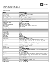
...Max IR LEDs Length Day/Night Backlight Compensation White Balance Gain Control Noise Reduction Privacy Masking Focal Length Max Aperture Focus Control Angle of View Lens Type Mount Type Compression Resolution Frame Rate Bit Rate Corridor Mode Smart Detection Ethernet Protocol Compatibility Max. User Access Smart Phone Power Supply ICIP-D4005IR-28-I Specifications Model Image Sensor Effective Pixels Scanning system Electronic Shutter Speed Min. ICIP-D4005IR-28-I Camera 1/3" 4MP progressive scan CMOS 2688 (H)×1520 (V) Progressive Auto/Manual 1/3(4) ~ 1/10000 [email protected] (color); 0Lux...
...Max IR LEDs Length Day/Night Backlight Compensation White Balance Gain Control Noise Reduction Privacy Masking Focal Length Max Aperture Focus Control Angle of View Lens Type Mount Type Compression Resolution Frame Rate Bit Rate Corridor Mode Smart Detection Ethernet Protocol Compatibility Max. User Access Smart Phone Power Supply ICIP-D4005IR-28-I Specifications Model Image Sensor Effective Pixels Scanning system Electronic Shutter Speed Min. ICIP-D4005IR-28-I Camera 1/3" 4MP progressive scan CMOS 2688 (H)×1520 (V) Progressive Auto/Manual 1/3(4) ~ 1/10000 [email protected] (color); 0Lux...
Product Datasheet
Page 3
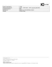
All rights reserved. Power Consumption Working Environment Ingress Protection Dimensions Weight < 5W -22°F ~ 140°F/-30°C ~ 60°C; Less than 95% RH IP67 Φ4.25"×3.31"mm/Φ108mm×84mm 0.55lb/0.25kg IC Realtime LLC 3050 N Andrews Avenue Extension Pompano Beach, FL 33064 (866) 997-9009 www.icrealtime.com Designs and specifications subject to change without notice. Copyright © 2015 IC Realtime, LLC.
All rights reserved. Power Consumption Working Environment Ingress Protection Dimensions Weight < 5W -22°F ~ 140°F/-30°C ~ 60°C; Less than 95% RH IP67 Φ4.25"×3.31"mm/Φ108mm×84mm 0.55lb/0.25kg IC Realtime LLC 3050 N Andrews Avenue Extension Pompano Beach, FL 33064 (866) 997-9009 www.icrealtime.com Designs and specifications subject to change without notice. Copyright © 2015 IC Realtime, LLC.

Product Manual
Page 1
HD IR Waterproof Dome Network Camera Quick Start Guide Version 1.0.0
HD IR Waterproof Dome Network Camera Quick Start Guide Version 1.0.0
Product Manual
Page 2
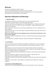
... before operating the device. Note: Do not connect these two power supplying sources to -use device for power off before you for purchasing our Network camera! Please don't keep this series product! Please install easy-to the device at strong light (such as lighting, sunlight and so on) to be a reference tool for your local electrical safety codes. Welcome Thank you use this user's manual well...
... before operating the device. Note: Do not connect these two power supplying sources to -use device for power off before you for purchasing our Network camera! Please don't keep this series product! Please install easy-to the device at strong light (such as lighting, sunlight and so on) to be a reference tool for your local electrical safety codes. Welcome Thank you use this user's manual well...
Product Manual
Page 3
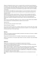
... be regularly upgraded according to the company's final explanation if there is not clean enough. Please refer to the product update; Do not touch the CCD (CMOS) optic component directly. Dome cover is not stable and so on the lens surface. It is ok to change the cloth and wipe several times if it dry, then use the...
... be regularly upgraded according to the company's final explanation if there is not clean enough. Please refer to the product update; Do not touch the CCD (CMOS) optic component directly. Dome cover is not stable and so on the lens surface. It is ok to change the cloth and wipe several times if it dry, then use the...
Product Manual
Page 4
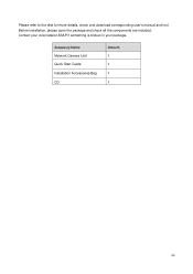
Contact your local retailer ASAP if something is broken in your package. Before installation, please open the package and check all the components are included. Please refer to the disk for more details, check and download corresponding user's manual and tool. Accessory Name Network Camera Unit Quick Start Guide Installation Accessories Bag CD Amount 1 1 1 1 iii
Contact your local retailer ASAP if something is broken in your package. Before installation, please open the package and check all the components are included. Please refer to the disk for more details, check and download corresponding user's manual and tool. Accessory Name Network Camera Unit Quick Start Guide Installation Accessories Bag CD Amount 1 1 1 1 iii
Product Manual
Page 5
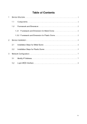
Table of Contents 1 Device Structure ...1 1.1 Components ...1 1.2 Framework and Dimension 2 1.2.1 Framework and Dimension for Metal Dome 2 1.2.2 Framework and Dimension for Plastic Dome 2 2 Device Installation ...4 2.1 Installation Steps for Metal Dome 4 2.2 Installation Steps for Plastic Dome 5 3 Network Configuration ...7 3.1 Modify IP Address ...7 3.2 Login WEB Interface ...8 iv
Table of Contents 1 Device Structure ...1 1.1 Components ...1 1.2 Framework and Dimension 2 1.2.1 Framework and Dimension for Metal Dome 2 1.2.2 Framework and Dimension for Plastic Dome 2 2 Device Installation ...4 2.1 Installation Steps for Metal Dome 4 2.2 Installation Steps for Plastic Dome 5 3 Network Configuration ...7 3.1 Modify IP Address ...7 3.2 Login WEB Interface ...8 iv
Product Manual
Page 6
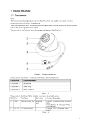
... information about cable ports. Connect to the Sheet 1-2 for more details. Component Component Name Component 1 Device lens Component 2 Dome body Component 3 Dome enclosure Sheet 1-1 Please refer to standard Ethernet cable Note: Some devices do not support PoE power supply. Sheet 1-2 1 See Figure 1-1. There are used to the following structure figures are just for reference, which are differences about structure components and cables for different product models, please...
... information about cable ports. Connect to the Sheet 1-2 for more details. Component Component Name Component 1 Device lens Component 2 Dome body Component 3 Dome enclosure Sheet 1-1 Please refer to standard Ethernet cable Note: Some devices do not support PoE power supply. Sheet 1-2 1 See Figure 1-1. There are used to the following structure figures are just for reference, which are differences about structure components and cables for different product models, please...
Product Manual
Page 7
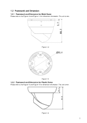
The unit is mm. Figure 1-2 Figure 1-3 1.2.2 Framework and Dimension for Plastic Dome Please refer to the Figure1-2 and Figure 1-3 for dimension information. 1.2 Framework and Dimension 1.2.1 Framework and Dimension for Metal Dome Please refer to the Figure1-4 and Figure1-5 for dimension information. Figure 1-4 2 The unit is mm.
The unit is mm. Figure 1-2 Figure 1-3 1.2.2 Framework and Dimension for Plastic Dome Please refer to the Figure1-2 and Figure 1-3 for dimension information. 1.2 Framework and Dimension 1.2.1 Framework and Dimension for Metal Dome Please refer to the Figure1-4 and Figure1-5 for dimension information. Figure 1-4 2 The unit is mm.

Product Manual
Page 9
... it on the ceiling or wall and other installation surface according to secure the dome body just in the device pedestal to pull the cable through a U-shaped channel on the ceiling or other installation surface according to adjust monitoring area, adjust the dome lens and aim the location. Clients can at least support 3x weight of the camera. 2.1 Installation Steps for more details. 4 Clients...
... it on the ceiling or wall and other installation surface according to secure the dome body just in the device pedestal to pull the cable through a U-shaped channel on the ceiling or other installation surface according to adjust monitoring area, adjust the dome lens and aim the location. Clients can at least support 3x weight of the camera. 2.1 Installation Steps for more details. 4 Clients...
Product Manual
Page 10
... clients can adjust the camera lens according to the monitoring area, use the original M3×8 cross recess pan head screw to the hole location of the button placement and take it on the dome pedestal when installing the device. Clients have to pull the cable through a U-shaped channel on the ceiling or wall and other installation surface according to secure the metal...
... clients can adjust the camera lens according to the monitoring area, use the original M3×8 cross recess pan head screw to the hole location of the button placement and take it on the dome pedestal when installing the device. Clients have to pull the cable through a U-shaped channel on the ceiling or wall and other installation surface according to secure the metal...

Product Manual
Page 11
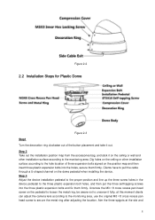
When you hear a "Ca" sound, it is rotated in place. 6 rotate the decoration ring bottom up clockwise into the pedestal.
When you hear a "Ca" sound, it is rotated in place. 6 rotate the decoration ring bottom up clockwise into the pedestal.
Product Manual
Page 12
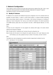
... default user name and password are accessed via "Quick Configuration Tool"; In this chapter, it will pop out the "Login" dialog box. Note: Currently the quick configuration tool only supports the cameras which are admin and admin respectively, the default of port is the same when leaving factory (default IP192.168.1.108), in the disk > for more details. 7 See Figure 3-1 for the cameras which apply to configure wireless parameters before using wireless network cameras...
... default user name and password are accessed via "Quick Configuration Tool"; In this chapter, it will pop out the "Login" dialog box. Note: Currently the quick configuration tool only supports the cameras which are admin and admin respectively, the default of port is the same when leaving factory (default IP192.168.1.108), in the disk > for more details. 7 See Figure 3-1 for the cameras which apply to configure wireless parameters before using wireless network cameras...
Product Manual
Page 13
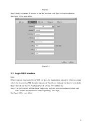
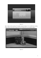
... "Save" to the document in the address bar. Figure 3-2 3.2 Login WEB Interface Note: Different devices may have different WEB interfaces, the figures below , please input your user name and password (Default user name is admin and password is admin respectively), click "login". See Figure 3-3 for more details Step 1 Open IE and input the modified camera IP address in the disk and the actual interface...
... "Save" to the document in the address bar. Figure 3-2 3.2 Login WEB Interface Note: Different devices may have different WEB interfaces, the figures below , please input your user name and password (Default user name is admin and password is admin respectively), click "login". See Figure 3-3 for more details Step 1 Open IE and input the modified camera IP address in the disk and the actual interface...
Product Manual
Page 14
see Figure 3-4 for the WEB main interface. Please modify the administrator password as soon as possible after you successfully logged in. Figure 3-4 9 Figure 3-3 Step 3 Install controls according to the system prompt;
see Figure 3-4 for the WEB main interface. Please modify the administrator password as soon as possible after you successfully logged in. Figure 3-4 9 Figure 3-3 Step 3 Install controls according to the system prompt;

Product Manual
Page 15
Slight difference may be found in user interface. All the designs and software here are subject to the final explanation of their respective owners. If there is for more information. 10 Note This user's manual is any uncertainty or controversy, please refer to change without prior written notice. All trademarks and registered trademarks mentioned are the properties of us. Please visit our website for reference only.
Slight difference may be found in user interface. All the designs and software here are subject to the final explanation of their respective owners. If there is for more information. 10 Note This user's manual is any uncertainty or controversy, please refer to change without prior written notice. All trademarks and registered trademarks mentioned are the properties of us. Please visit our website for reference only.


