Datasheet
Page 1
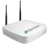
... between network video products regardless of surveillance. The recording options and schedules can be programmed to all Clearview and IC Realtime series products, this NVR. H.264 Like all cameras.. 1 | www.icrealtime.com FS-02032020-HV1-D1.00 The recorder monitors incoming video and can also be set for each channel up to 6MP ● Max 80Mbps incoming bandwidth ● Built in WiFi, Support One Key Setup ● Support...
... between network video products regardless of surveillance. The recording options and schedules can be programmed to all Clearview and IC Realtime series products, this NVR. H.264 Like all cameras.. 1 | www.icrealtime.com FS-02032020-HV1-D1.00 The recorder monitors incoming video and can also be set for each channel up to 6MP ● Max 80Mbps incoming bandwidth ● Built in WiFi, Support One Key Setup ● Support...

Datasheet
Page 2
...Rate Record Mode Record Interval 48~ 8192kbps Manual, Schedule(Regular(Continuous), MD, Alarm), Stop 1~120 min (default: 60 min), Pre-record: 1~30 sec, Post-record: 10~300 sec Video Detection & Alarm Trigger Events Video Detection Alarm Input Recording, PTZ, Tour, Video Push, Email, FTP, Snapshot, Buzzer & Screen tips Motion Detection, MD Zones: 396(22×18), Video Loss & Camera Blank N/A Relay Output N/A Playback & Backup SOySnDc PMlaeynbuack SVeidarecohInMtoedrfeace Audio Interface PRlaSy4b8a5ck Functions Alarm BEalcekcutprMicoadle Network Ethernet Wireless Network Network Functions...
...Rate Record Mode Record Interval 48~ 8192kbps Manual, Schedule(Regular(Continuous), MD, Alarm), Stop 1~120 min (default: 60 min), Pre-record: 1~30 sec, Post-record: 10~300 sec Video Detection & Alarm Trigger Events Video Detection Alarm Input Recording, PTZ, Tour, Video Push, Email, FTP, Snapshot, Buzzer & Screen tips Motion Detection, MD Zones: 396(22×18), Video Loss & Camera Blank N/A Relay Output N/A Playback & Backup SOySnDc PMlaeynbuack SVeidarecohInMtoedrfeace Audio Interface PRlaSy4b8a5ck Functions Alarm BEalcekcutprMicoadle Network Ethernet Wireless Network Network Functions...

Product Manual
Page 2
Table of Contents 1 Hardware Installation and Connection 1 1.1 Check Unpacked NVR 1 1.2 About Front Panel and Rear Panel 1 1.3 After Remove the Chassis 1 1.4 HDD Installation ...1 1.5 Front Panel ...3 1.6 Rear Panel ...4 2 GUI Operation...8 2.1 Boot up ...8 2.2 Login ...8 2.3 Smart Add ...9 2.4 Remote Device...10 2.5 Schedule ...12 2.6 Realtime Playback 14 3 Web Operation...16 3.1 Network Connection 16 3.2 Login ...17 3.3 Main Window ...17 i
Table of Contents 1 Hardware Installation and Connection 1 1.1 Check Unpacked NVR 1 1.2 About Front Panel and Rear Panel 1 1.3 After Remove the Chassis 1 1.4 HDD Installation ...1 1.5 Front Panel ...3 1.6 Rear Panel ...4 2 GUI Operation...8 2.1 Boot up ...8 2.2 Login ...8 2.3 Smart Add ...9 2.4 Remote Device...10 2.5 Schedule ...12 2.6 Realtime Playback 14 3 Web Operation...16 3.1 Network Connection 16 3.2 Login ...17 3.3 Main Window ...17 i

Product Manual
Page 4
... the components are using the same model! The product must be done by manufacturer. This series product shall be transported, storage and used in a cool, dry place away from extreme humid places; Avoid violent vibration; Do not put other devices on the NVR. 4.Qualified engineers needed All the examination and repair work should be...
... the components are using the same model! The product must be done by manufacturer. This series product shall be transported, storage and used in a cool, dry place away from extreme humid places; Avoid violent vibration; Do not put other devices on the NVR. 4.Qualified engineers needed All the examination and repair work should be...

Product Manual
Page 6
... installation and operations here should conform to check the accessories. Finally you to the User's Manual included in accordance with the four holes in the rear panel is optional). Then you replace the HDD. Usually we do not recommend the PC HDD. 1.4.1 WiFI-NVR-4 Series ○1 . Please use HDD of NVR is secure or not. 1.4 HDD Installation Important: Please turn off the power...
... installation and operations here should conform to check the accessories. Finally you to the User's Manual included in accordance with the four holes in the rear panel is optional). Then you replace the HDD. Usually we do not recommend the PC HDD. 1.4.1 WiFI-NVR-4 Series ○1 . Please use HDD of NVR is secure or not. 1.4 HDD Installation Important: Please turn off the power...

Product Manual
Page 8
... when the network 3 light connection is abnormal. 1.5.2 Phoenix-32HP+ Series The series front panel is shown as in Figure 1-1. and the HDD port respectively. Figure 1-2 Please refer to the HDD port. 1.5 Front Panel 1.5.1 WiFI-NVR-4 Series The front panel is shown as in Figure 1-2. Loosen the power cable of the chassis and connect another end of the rear panel. to the following sheet for...
... when the network 3 light connection is abnormal. 1.5.2 Phoenix-32HP+ Series The series front panel is shown as in Figure 1-1. and the HDD port respectively. Figure 1-2 Please refer to the HDD port. 1.5 Front Panel 1.5.1 WiFI-NVR-4 Series The front panel is shown as in Figure 1-2. Loosen the power cable of the chassis and connect another end of the rear panel. to the following sheet for...

Product Manual
Page 9
...-NVR-4 Series The rear panel is shown as below. Connect to the HDMI port of the display device. The blue light is on when the network connection is abnormal. It can connect to the monitor to mouse, USB storage device, USB burner and etc. 10M/100Mbps self-adaptive Ethernet port. Connect to view analog video. Icon NET POWER Name Network status indicator light Power status indicator light USB2.0 port Function The blue light...
...-NVR-4 Series The rear panel is shown as below. Connect to the HDMI port of the display device. The blue light is on when the network connection is abnormal. It can connect to the monitor to mouse, USB storage device, USB burner and etc. 10M/100Mbps self-adaptive Ethernet port. Connect to view analog video. Icon NET POWER Name Network status indicator light Power status indicator light USB2.0 port Function The blue light...

Product Manual
Page 10
... Function Power switch / Power on 1-window video playback. Port Name / MIC IN MIC OUT PoE PORT Wireless AP Connection Power input port Audio input port Function Power socket. For NVR41 series, input DC 12V/2A. For NVR41-P series, input DC 48V/1.5A. For NVR41-8P series, input DC 48V/2A. PoE port Built-in switch. For PoE series product, you can use this port to provide power to the network camera when there is to output...
... Function Power switch / Power on 1-window video playback. Port Name / MIC IN MIC OUT PoE PORT Wireless AP Connection Power input port Audio input port Function Power socket. For NVR41 series, input DC 12V/2A. For NVR41-P series, input DC 48V/1.5A. For NVR41-8P series, input DC 48V/2A. PoE port Built-in switch. For PoE series product, you can use this port to provide power to the network camera when there is to output...

Product Manual
Page 11
... sure the device and the NVR have the same ground. It can connect to the control devices such as the alarm detector. +12V power output port. USB2.0 port USB2.0 port. RS232 COM. Output analog video signal. NO (normal open alarm output port. You can provide the power to view analog video. 6 It can connect to the monitor to some devices such as speed dome PTZ. Connect to the external alarm device. Name 1~16...
... sure the device and the NVR have the same ground. It can connect to the control devices such as the alarm detector. +12V power output port. USB2.0 port USB2.0 port. RS232 COM. Output analog video signal. NO (normal open alarm output port. You can provide the power to view analog video. 6 It can connect to the monitor to some devices such as speed dome PTZ. Connect to the external alarm device. Name 1~16...

Product Manual
Page 13
... interface. Please input user name and password. Password: admin. Username: 888888. See Figure 2-2. System consists of four accounts: Username: admin. After device booted up, the system is in multiple-channel display mode by default. 2.2 Login After device booted up, the system goes to login interface. 2 GUI Operation 2.1 Boot up Caution Before the boot up, please make sure the power wire connection is OK. See...
... interface. Please input user name and password. Password: admin. Username: 888888. See Figure 2-2. System consists of four accounts: Username: admin. After device booted up, the system is in multiple-channel display mode by default. 2.2 Login After device booted up, the system goes to login interface. 2 GUI Operation 2.1 Boot up Caution Before the boot up, please make sure the power wire connection is OK. See...

Product Manual
Page 14
... Smart add button. Within 30 minutes, three times login failure will result in system alarm and five times login failure will result in the same router or switch, you first login. Figure 2-3 On the preview interface, right click mouse and then select Smart add. See Figure 2-4. 9 Password: 666666. Username: default. See Figure 2-3. There are in account lock! 2.3 Smart Add When the network camera(s) and the NVR...
... Smart add button. Within 30 minutes, three times login failure will result in system alarm and five times login failure will result in the same router or switch, you first login. Figure 2-3 On the preview interface, right click mouse and then select Smart add. See Figure 2-4. 9 Password: 666666. Username: default. See Figure 2-3. There are in account lock! 2.3 Smart Add When the network camera(s) and the NVR...

Product Manual
Page 15
See Figure 2-5. Figure 2-5 Tips In the preview interface, for the channel of no IPC connection, you can click the icon "+" in the centre of the interface to quickly go to the user's manual for detailed information. 2.4 Remote Device From Main menu->Setting->Camera->Remote device or right click mouse on the preview interface and then select remote device item, you can see the following interface. See Figure 2-6. 10 Figure 2-4 Please refer to the Remote Device interface.
See Figure 2-5. Figure 2-5 Tips In the preview interface, for the channel of no IPC connection, you can click the icon "+" in the centre of the interface to quickly go to the user's manual for detailed information. 2.4 Remote Device From Main menu->Setting->Camera->Remote device or right click mouse on the preview interface and then select remote device item, you can see the following interface. See Figure 2-6. 10 Figure 2-4 Please refer to the Remote Device interface.

Product Manual
Page 16
... your network camera manufacturer for ClearView, Panasonic, Sony, Dynacolor, Samsung, AXIS, Arecont, ONVIF and custom. System supports batch add function. Figure 2-6 Click Device Search button, you can view the searched IP addresses at the top pane of the interface. Double click an IP address or check one IP address and then click Add button, you can just input URL address, user name and password connect to...
... your network camera manufacturer for ClearView, Panasonic, Sony, Dynacolor, Samsung, AXIS, Arecont, ONVIF and custom. System supports batch add function. Figure 2-6 Click Device Search button, you can view the searched IP addresses at the top pane of the interface. Double click an IP address or check one IP address and then click Add button, you can just input URL address, user name and password connect to...

Product Manual
Page 17
... There are four types: Regular/MD (motion detect)/Alarm/MD&Alarm. Week day: There are total six periods. You can go to Main menu->Setting->System->General->Holiday to implement the following operations. After the system booted up, it to delete a record type from Saturday to set record type and time in default 24-hour regular mode. There are eight options: ranges...
... There are four types: Regular/MD (motion detect)/Alarm/MD&Alarm. Week day: There are total six periods. You can go to Main menu->Setting->System->General->Holiday to implement the following operations. After the system booted up, it to delete a record type from Saturday to set record type and time in default 24-hour regular mode. There are eight options: ranges...

Product Manual
Page 18
... card and there is no risk of the network camera in case the network connection fails. See Figure 2-8. Please following the steps listed below to add holiday first. See Figure 2-9. It allows you backup recorded file in one day. There are four record types: regular, motion detection (MD), Alarm, MD & alarm. Otherwise you can not see an interface shown as redundant. (Main menu->Setting->Storage...
... card and there is no risk of the network camera in case the network connection fails. See Figure 2-8. Please following the steps listed below to add holiday first. See Figure 2-9. It allows you backup recorded file in one day. There are four record types: regular, motion detection (MD), Alarm, MD & alarm. Otherwise you can not see an interface shown as redundant. (Main menu->Setting->Storage...

Product Manual
Page 19
After completing all the setups please click save button, system goes back to select the corresponding function. Green color stands for regular recording, yellow color stands for motion detection and red color stands for your reference. There are color bars for alarm recording. The white means the MD and alarm record is valid. Please check the box to the previous menu. Once you have set to record when the MD and alarm occurs, system will not record neither motion detect occurs nor the alarm occurs. Figure 2-11 2.6 Realtime Playback Preview control interface Figure 2-12 14
After completing all the setups please click save button, system goes back to select the corresponding function. Green color stands for regular recording, yellow color stands for motion detection and red color stands for your reference. There are color bars for alarm recording. The white means the MD and alarm record is valid. Please check the box to the previous menu. Once you have set to record when the MD and alarm occurs, system will not record neither motion detect occurs nor the alarm occurs. Figure 2-11 2.6 Realtime Playback Preview control interface Figure 2-12 14

Product Manual
Page 20
...System may pop up the preview control interface. Move you mouse to the top centre of the video of current channel. Please go to the Main Menu->Setting->System->General to playback the previous 5-60 minutes record of current channel, you can ...no such record in this area for more than 6 seconds and has no operation, the control bar automatically hides. 1 2 34 5 6 Figure 2-13 SN Name SN Name SN Name 1 Realtime playback 2 Digital zoom 3 Manual record 4 Manual Snapshot 5 Bidirectional talk 6 Remote device Realtime playback button is to set real-time playback time. If ...
...System may pop up the preview control interface. Move you mouse to the top centre of the video of current channel. Please go to the Main Menu->Setting->System->General to playback the previous 5-60 minutes record of current channel, you can ...no such record in this area for more than 6 seconds and has no operation, the control bar automatically hides. 1 2 34 5 6 Figure 2-13 SN Name SN Name SN Name 1 Realtime playback 2 Digital zoom 3 Manual record 4 Manual Snapshot 5 Bidirectional talk 6 Remote device Realtime playback button is to set real-time playback time. If ...

Product Manual
Page 21
Web includes several modules: Monitor channel preview, record search, alarm setup, system configuration, PTZ control, monitor window and etc. 3.1 Network Connection Before web client operation, please check the following operation is based on the Apple PC. Now system is trying to un-install the web control, please run uninstall webrec2.0.bat. You can see the corresponding digital channel becomes idle (disable). a) If it is your first time to insert PoE, system can map...
Web includes several modules: Monitor channel preview, record search, alarm setup, system configuration, PTZ control, monitor window and etc. 3.1 Network Connection Before web client operation, please check the following operation is based on the Apple PC. Now system is trying to un-install the web control, please run uninstall webrec2.0.bat. You can see the corresponding digital channel becomes idle (disable). a) If it is your first time to insert PoE, system can map...

Product Manual
Page 22
...to make sure current IPC has connected or not. For example, if your IE security setup. Default factory name is admin and password is free. Otherwise, it goes to the next step: d) Fourthly, system goes to ask you whether install Web plug-in use now. System pops up warning ...address column. Note: For security reasons, please modify your password after you can't download the ActiveX file, please modify your NVR IP is the name of current PoE port. address, otherwise it can refresh to the --- System can not select. 3.2 Login Open IE and input NVR address in IE address...
...to make sure current IPC has connected or not. For example, if your IE security setup. Default factory name is admin and password is free. Otherwise, it goes to the next step: d) Fourthly, system goes to ask you whether install Web plug-in use now. System pops up warning ...address column. Note: For security reasons, please modify your password after you can't download the ActiveX file, please modify your NVR IP is the name of current PoE port. address, otherwise it can refresh to the --- System can not select. 3.2 Login Open IE and input NVR address in IE address...

Product Manual
Page 23
Figure 3-2 3.3.2 WAN Login In WAN mode, after you logged in, you can view the real-time video. Note 18 For the LAN mode, after you logged in, the interface is shown as below. you can see the main window. Figure 3-3 For detailed operation information, please refer to the User's Manual included in the resources CD. See Figure 3-3. See Figure 3-2. Click the channel name on the left side;
Figure 3-2 3.3.2 WAN Login In WAN mode, after you logged in, you can view the real-time video. Note 18 For the LAN mode, after you logged in, the interface is shown as below. you can see the main window. Figure 3-3 For detailed operation information, please refer to the User's Manual included in the resources CD. See Figure 3-3. See Figure 3-2. Click the channel name on the left side;


