
Configuration Guide
Page 5
... This Document iii Conventions ...iii Contents ...v Introduction ...1 1.1 Basic Settings for Access Points 1 1.2 Recommended Settings for Root Access Point 2 Extending a Network's Radio Coverage 4 2.1 One-Hop Wireless Network Example 4 2.2 Two-Hop Wireless Network Example 4 Verifying Wireless AP Operations 6 3.1 Viewing the WLAP RF Statistics Screen 6 3.2 Viewing the Known Access Points Screen 7 3.3 Observing the Access Point's LED Indicators 8 3.3.1 Functional State 9 3.3.2 Send Probe State 9 Using the Link...
... This Document iii Conventions ...iii Contents ...v Introduction ...1 1.1 Basic Settings for Access Points 1 1.2 Recommended Settings for Root Access Point 2 Extending a Network's Radio Coverage 4 2.1 One-Hop Wireless Network Example 4 2.2 Two-Hop Wireless Network Example 4 Verifying Wireless AP Operations 6 3.1 Viewing the WLAP RF Statistics Screen 6 3.2 Viewing the Known Access Points Screen 7 3.3 Observing the Access Point's LED Indicators 8 3.3.1 Functional State 9 3.3.2 Send Probe State 9 Using the Link...
Configuration Guide
Page 7
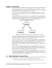
... requests and probe responses to bridge two Ethernet networks. The other access points. The procedures and examples in the Intel® PRO/Wireless 2011/2011B LAN Point Product Reference Guides available on the Intel support web site at www.support.Intel.com. 1.1 Basic Settings for Access Points For a wireless Access Point (AP) operation, make sure that all access points have: • The same ESS ID (Net ID) on...
... requests and probe responses to bridge two Ethernet networks. The other access points. The procedures and examples in the Intel® PRO/Wireless 2011/2011B LAN Point Product Reference Guides available on the Intel support web site at www.support.Intel.com. 1.1 Basic Settings for Access Points For a wireless Access Point (AP) operation, make sure that all access points have: • The same ESS ID (Net ID) on...
Configuration Guide
Page 8
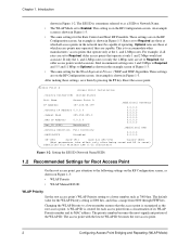
... root access point. 2 Configuring Access Point Bridging and Repeating (WLAP Mode) Intel recommends setting rates 1 and 2 Mbps to Required and 5.5 and 11 Mbps to accommodate other manufacturers' access points that operate only at only 1 and 2 Mbps would associate. After making these settings, save them by pressing the F1 key. Reset the access point. This is reset) Identifies this Wireless LAN (1-32...
... root access point. 2 Configuring Access Point Bridging and Repeating (WLAP Mode) Intel recommends setting rates 1 and 2 Mbps to Required and 5.5 and 11 Mbps to accommodate other manufacturers' access points that operate only at only 1 and 2 Mbps would associate. After making these settings, save them by pressing the F1 key. Reset the access point. This is reset) Identifies this Wireless LAN (1-32...
Configuration Guide
Page 9
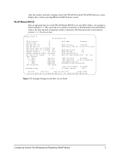
WLAP Manual BSS ID Intel recommends that you set link required WLAP operation. This causes the access point to go directly to the Functional state and therefore reduces the time required to its own MAC address. Access Point A RF Configuration .DTIM Interval 10 .BC/MC Q Max 10 .Max Retries (d) 15 .Max ...RF Preamble Disabled Tx Power Control Full OK-[CR] Save-[F1] Save All APs-[F2] Cancel-[ESC] Use the space bar to enable/disable/set the WLAP Manual BSS ID to begin the wireless connection. An example is shown in section 3.3.1: Functional State. The Functional ...
WLAP Manual BSS ID Intel recommends that you set link required WLAP operation. This causes the access point to go directly to the Functional state and therefore reduces the time required to its own MAC address. Access Point A RF Configuration .DTIM Interval 10 .BC/MC Q Max 10 .Max Retries (d) 15 .Max ...RF Preamble Disabled Tx Power Control Full OK-[CR] Save-[F1] Save All APs-[F2] Cancel-[ESC] Use the space bar to enable/disable/set the WLAP Manual BSS ID to begin the wireless connection. An example is shown in section 3.3.1: Functional State. The Functional ...
Configuration Guide
Page 10
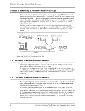
...RF Configuration screen in Figure 2-1 and Figure 2-2. The Manual BSS ID for access point C. Examples of one hop between two nodes of the root access point A. Figure 2-1: Wireless AP Network with One Hop 2.1 One-Hop Wireless Network Example The example in Figure 2-1 extends a network's radio coverage with one... shown in Figure 2-3 shows the WLAP Manual BSS ID setting for the root access point A is one -hop and two-hop wireless AP operations. Chapter 2. With regard to wireless AP operations, the number of access point B and the WLAP Manual BSS ID on B to its own MAC address....
...RF Configuration screen in Figure 2-1 and Figure 2-2. The Manual BSS ID for access point C. Examples of one hop between two nodes of the root access point A. Figure 2-1: Wireless AP Network with One Hop 2.1 One-Hop Wireless Network Example The example in Figure 2-1 extends a network's radio coverage with one... shown in Figure 2-3 shows the WLAP Manual BSS ID setting for the root access point A is one -hop and two-hop wireless AP operations. Chapter 2. With regard to wireless AP operations, the number of access point B and the WLAP Manual BSS ID on B to its own MAC address....
Configuration Guide
Page 11
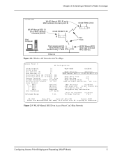
... 0 mi. Host Computer 00:A0:F8:8B:71:45 B Root access point A 00:A0:F8:93:C5:B5 WLAP Priority = 7000 Ethernet Figure 2-2: Wireless AP Network with which this AP is going to MAC address of access point A. Figure 2-3: WLAP Manual BSS ID on Access Point C in 2-Hop Network Configuring Access Point Bridging and Repeating (WLAP Mode) 5 Extending a Network's Radio Coverage...
... 0 mi. Host Computer 00:A0:F8:8B:71:45 B Root access point A 00:A0:F8:93:C5:B5 WLAP Priority = 7000 Ethernet Figure 2-2: Wireless AP Network with which this AP is going to MAC address of access point A. Figure 2-3: WLAP Manual BSS ID on Access Point C in 2-Hop Network Configuring Access Point Bridging and Repeating (WLAP Mode) 5 Extending a Network's Radio Coverage...
Configuration Guide
Page 12
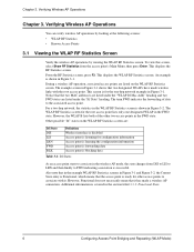
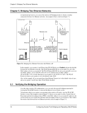
... Figure 3-1. However, Functional does not necessarily mean that two designated WLAPs have made a wireless AP connection. The example screen in the section titled 3.3.1: Functional State. 6 Configuring Access Point Bridging and Repeating (WLAP Mode) Verifying Wireless AP Operations Chapter 3. Chapter 3. During a wireless AP operation, associated access points are listed under the "Itf State" heading. The term FWD indicates the forwarding of...
... Figure 3-1. However, Functional does not necessarily mean that two designated WLAPs have made a wireless AP connection. The example screen in the section titled 3.3.1: Functional State. 6 Configuring Access Point Bridging and Repeating (WLAP Mode) Verifying Wireless AP Operations Chapter 3. Chapter 3. During a wireless AP operation, associated access points are listed under the "Itf State" heading. The term FWD indicates the forwarding of...
Configuration Guide
Page 13
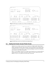
... the root access point but may not be part of a Known Access Points screen listing the root access point and the two designated WLAPs. This example screen includes another access point connected to the same Ethernet as the root access point but not in the wireless AP network. Figure 3-3 is an example of the wireless AP operation. Configuring Access Point Bridging and Repeating (WLAP Mode) 7 Access Point A Current...
... the root access point but may not be part of a Known Access Points screen listing the root access point and the two designated WLAPs. This example screen includes another access point connected to the same Ethernet as the root access point but not in the wireless AP network. Figure 3-3 is an example of the wireless AP operation. Configuring Access Point Bridging and Repeating (WLAP Mode) 7 Access Point A Current...
Configuration Guide
Page 14
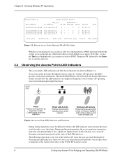
The Intel® PRO/Wireless 2011/2011B LAN Product Reference Guides describe how the LED indicators are displayed during the several wireless AP operating states from Initializing through the various states of a wireless AP operation, the LEDs provide certain status indications. Continuously on the WLAP RF Statistics screen. 8 Configuring Access Point Bridging and Repeating (WLAP Mode) As an access point proceeds through Functional. The...
The Intel® PRO/Wireless 2011/2011B LAN Product Reference Guides describe how the LED indicators are displayed during the several wireless AP operating states from Initializing through the various states of a wireless AP operation, the LEDs provide certain status indications. Continuously on the WLAP RF Statistics screen. 8 Configuring Access Point Bridging and Repeating (WLAP Mode) As an access point proceeds through Functional. The...
Configuration Guide
Page 15
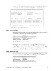
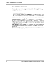
...is shown in the Send Probe State 3.3.1 Functional State The Functional state means that the access point is in the Itf State column, then the current access point has made a wireless AP connection. Access Point A Current # WLAP Itf 0 Current State Priority Send Probe 8000 hex WLAP RF ...a wireless AP connection. Functional State When the access point is ready for mobile units or other access points to associate with it may or may remain in Figure 3-1 and Figure 32. In this state, the LED indicators display as follows: Indicator Power Wired LAN Activity Wireless LAN Activity...
...is shown in the Send Probe State 3.3.1 Functional State The Functional state means that the access point is in the Itf State column, then the current access point has made a wireless AP connection. Access Point A Current # WLAP Itf 0 Current State Priority Send Probe 8000 hex WLAP RF ...a wireless AP connection. Functional State When the access point is ready for mobile units or other access points to associate with it may or may remain in Figure 3-1 and Figure 32. In this state, the LED indicators display as follows: Indicator Power Wired LAN Activity Wireless LAN Activity...
Configuration Guide
Page 16
Send Probe State This occurs when an access point is configured to run in a wireless AP operation but is set to the zero default value, the access point remains in the Send Probe state for approximately 30 seconds and then goes to the Functional state. For condition ...is set to the MAC address of the MAC address from 00 to the Functional state. 10 Configuring Access Point Bridging and Repeating (WLAP Mode) For condition b, the Ethernet connection must be restored before the access point can associate and go to 01; Verifying Wireless AP Operations Table 3-3: LED Indicators -
Send Probe State This occurs when an access point is configured to run in a wireless AP operation but is set to the zero default value, the access point remains in the Send Probe state for approximately 30 seconds and then goes to the Functional state. For condition ...is set to the MAC address of the MAC address from 00 to the Functional state. 10 Configuring Access Point Bridging and Repeating (WLAP Mode) For condition b, the Ethernet connection must be restored before the access point can associate and go to 01; Verifying Wireless AP Operations Table 3-3: LED Indicators -
Configuration Guide
Page 17
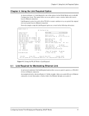
... Network examples using the Link Required option are covered in the event it resets then makes a wireless link to another root access point if the original root access point loses its Ethernet connection. Access Point A RF Configuration .DTIM Interval 10 .BC/MC Q Max 10 .Max Retries (d) 15 .Max...APs-[F2] Cancel-[ESC] Use the space bar to Link Required 4.1 Link Required for the WLAP Mode entry on the RF Configuration screen. An example network is one of the options for Maintaining Ethernet Link As previously mentioned, the Link Required option allows an access point...
... Network examples using the Link Required option are covered in the event it resets then makes a wireless link to another root access point if the original root access point loses its Ethernet connection. Access Point A RF Configuration .DTIM Interval 10 .BC/MC Q Max 10 .Max Retries (d) 15 .Max...APs-[F2] Cancel-[ESC] Use the space bar to Link Required 4.1 Link Required for the WLAP Mode entry on the RF Configuration screen. An example network is one of the options for Maintaining Ethernet Link As previously mentioned, the Link Required option allows an access point...
Configuration Guide
Page 19
... access point A's Ethernet connection is restored, WLAPs B and C roams back to access point D. Furthermore, if access point D loses its Ethernet connection. Using the Link Required Option Access Point A Current # WLAP Itf 0 Current State Priority Functional 8000 hex WLAP RF Statistics Root Interface Root Priority Root MAC Addr Root Path Cost 0 8000 hex 00:A0:F8:93:C5:B5 0 Wireless AP...
... access point A's Ethernet connection is restored, WLAPs B and C roams back to access point D. Furthermore, if access point D loses its Ethernet connection. Using the Link Required Option Access Point A Current # WLAP Itf 0 Current State Priority Functional 8000 hex WLAP RF Statistics Root Interface Root Priority Root MAC Addr Root Path Cost 0 8000 hex 00:A0:F8:93:C5:B5 0 Wireless AP...
Configuration Guide
Page 21
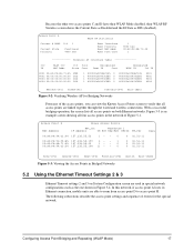
... detect(30-255 secs), 2,3,4 WLAP detect, 1 hardware detect, 0 disable Figure 4-6: Setting the Ethernet Timeout to the Channel setting. For wireless AP operations, it is not necessary to make any changes to 1 Configuring Access Point Bridging and Repeating (WLAP Mode) 15 To view the adopted channel number, refer to the System Summary screen. Channel Setting.
... detect(30-255 secs), 2,3,4 WLAP detect, 1 hardware detect, 0 disable Figure 4-6: Setting the Ethernet Timeout to the Channel setting. For wireless AP operations, it is not necessary to make any changes to 1 Configuring Access Point Bridging and Repeating (WLAP Mode) 15 To view the adopted channel number, refer to the System Summary screen. Channel Setting.
Configuration Guide
Page 22
...) is shown in Figure 5-2 shows access point A with Wireless AP In the example, access points A and B have their WLAP Mode set to its own MAC address. The WLAP Priority for these access points is set to access point A. This verifies the wireless link between two Ethernet networks. WLAP ...by viewing the WLAP RF Statistics screen and the Known Access Points screen. Bridging Two Ethernet Networks Chapter 5. To determine which access points are operating in the other wireless AP configurations, you can use the wireless AP bridging feature to the default value of Figure 5-1. 16...
...) is shown in Figure 5-2 shows access point A with Wireless AP In the example, access points A and B have their WLAP Mode set to its own MAC address. The WLAP Priority for these access points is set to access point A. This verifies the wireless link between two Ethernet networks. WLAP ...by viewing the WLAP RF Statistics screen and the Known Access Points screen. Bridging Two Ethernet Networks Chapter 5. To determine which access points are operating in the other wireless AP configurations, you can use the wireless AP bridging feature to the default value of Figure 5-1. 16...
Configuration Guide
Page 23
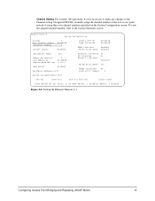
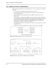
...] Exit-[ESC] Figure 5-2: Verifying Wireless AP for the special network. Configuring Access Point Bridging and Repeating (WLAP Mode) 17 Figure 5-3 is an example screen showing all access points on System Configuration screen are able to roam from access point D to verify that all access points are linked together through the wired and wireless connections. Because the other two access points C and D have their...
...] Exit-[ESC] Figure 5-2: Verifying Wireless AP for the special network. Configuring Access Point Bridging and Repeating (WLAP Mode) 17 Figure 5-3 is an example screen showing all access points on System Configuration screen are able to roam from access point D to verify that all access points are linked together through the wired and wireless connections. Because the other two access points C and D have their...
Configuration Guide
Page 26
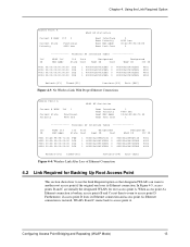
...- 6 1 Transmit+ 2 Transmit- 3 Receive+ 6 Receive- Chapter 5. Figure 5-5: Wiring Connections of Cross-Over 10BaseT Cable Access Point C WLAP RF Statistics Current # WLAP Current State Priority Itf 1 WLAP Lost on Ethernet" and the Wireless Interface (Itf) State as "WLAP Lost on Ethernet 8000 hex Root Interface Root Priority Root MAC Addr Root... Path Cost 0 8000 hex 00:A0:F8:94:C3:64 0 Wireless AP Interface Table Itf WLAP Itf Itf Path Designated Designated ID MAC Addr State Cost Root ID Cost WLAP ID Itf ID 8001...
...- 6 1 Transmit+ 2 Transmit- 3 Receive+ 6 Receive- Chapter 5. Figure 5-5: Wiring Connections of Cross-Over 10BaseT Cable Access Point C WLAP RF Statistics Current # WLAP Current State Priority Itf 1 WLAP Lost on Ethernet" and the Wireless Interface (Itf) State as "WLAP Lost on Ethernet 8000 hex Root Interface Root Priority Root MAC Addr Root... Path Cost 0 8000 hex 00:A0:F8:94:C3:64 0 Wireless AP Interface Table Itf WLAP Itf Itf Path Designated Designated ID MAC Addr State Cost Root ID Cost WLAP ID Itf ID 8001...
Configuration Guide
Page 31
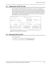
...Set up the two access points as shown in the previous section. 2. Local Access Point Current # WLAP Itf 1 Current State Priority Functional 7000 hex WLAP RF Statistics Root Interface Root Priority Root MAC Addr Root Path Cost 0 7000 hex 00:A0:F8:93:C5:B5 0 Wireless AP Interface Table Itf WLAP...Refresh-[F1] Timed-[F2] Previous-[F4] Exit-[ESC] Figure 6-4: Verifying the Wireless AP Operation 6.4 Running the RF Link Test To run the RF Link Test, make sure that the Current State is Functional and the Itf State is shown in Figure 6-4. An example of the remote access point.
...Set up the two access points as shown in the previous section. 2. Local Access Point Current # WLAP Itf 1 Current State Priority Functional 7000 hex WLAP RF Statistics Root Interface Root Priority Root MAC Addr Root Path Cost 0 7000 hex 00:A0:F8:93:C5:B5 0 Wireless AP Interface Table Itf WLAP...Refresh-[F1] Timed-[F2] Previous-[F4] Exit-[ESC] Figure 6-4: Verifying the Wireless AP Operation 6.4 Running the RF Link Test To run the RF Link Test, make sure that the Current State is Functional and the Itf State is shown in Figure 6-4. An example of the remote access point.
Configuration Guide
Page 33
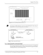
...Running the RF Link Test with Telnet For access point networks that are already installed, it may also affect the RF Link Test. Local Access Point MAC Addr: 00:A0:F8:93:C5:B5 Remote Access Point MAC Addr: 00:A0:F8:94:C2:04 Wireless AP Link Portable Computer Running the RF Link Test... Figure 6-7: Basic Setup for Aligning Directional Antennas. RF Link Test Local Access Point Connection Quality Test Remote ...
...Running the RF Link Test with Telnet For access point networks that are already installed, it may also affect the RF Link Test. Local Access Point MAC Addr: 00:A0:F8:93:C5:B5 Remote Access Point MAC Addr: 00:A0:F8:94:C2:04 Wireless AP Link Portable Computer Running the RF Link Test... Figure 6-7: Basic Setup for Aligning Directional Antennas. RF Link Test Local Access Point Connection Quality Test Remote ...
Configuration Guide
Page 34
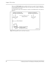
... subnet mask of the computer are appropriate for the network and access point. IP Address 157.235.55.199 MAC Addr: 00:A0:F8:93:C5:B5 IP Address 157.235.55.53 MAC Addr: 00:A0:F8:94:C2:04 Wireless AP Link Ethernet Network IP Address 157.235.55.50 Portable Computer... Running the RF Link Test Figure 6-8: Running RF Link Test with Telnet Connection LAPTOPLITE2.CDR, AP11MB3DSHADED.CDR 28 Configuring Access Point Bridging and Repeating (WLAP Mode) Chapter 6.
... subnet mask of the computer are appropriate for the network and access point. IP Address 157.235.55.199 MAC Addr: 00:A0:F8:93:C5:B5 IP Address 157.235.55.53 MAC Addr: 00:A0:F8:94:C2:04 Wireless AP Link Ethernet Network IP Address 157.235.55.50 Portable Computer... Running the RF Link Test Figure 6-8: Running RF Link Test with Telnet Connection LAPTOPLITE2.CDR, AP11MB3DSHADED.CDR 28 Configuring Access Point Bridging and Repeating (WLAP Mode) Chapter 6.