
Configuration Guide
Page 8
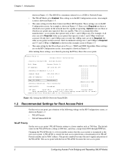
... Priority • WLAP Manual BSS ID WLAP Priority Set the root access point's WLAP Priority setting to Required, the older access points would not associate. Optional rates are those at the 1- and 2-Mbps rates. If only the 1- Intel recommends setting rates 1 and 2 Mbps to Required and 5.5 and ... screen. An example is reset) Identifies this Wireless LAN (1-32 characters) Figure 1-2: Setting the ESS ID (Network Name/SSID) 1.2 Recommended Settings for the WLAP Priority setting is to the following settings on the RF Configuration screen, as the root access point. This is 8000 hex,...
... Priority • WLAP Manual BSS ID WLAP Priority Set the root access point's WLAP Priority setting to Required, the older access points would not associate. Optional rates are those at the 1- and 2-Mbps rates. If only the 1- Intel recommends setting rates 1 and 2 Mbps to Required and 5.5 and ... screen. An example is reset) Identifies this Wireless LAN (1-32 characters) Figure 1-2: Setting the ESS ID (Network Name/SSID) 1.2 Recommended Settings for the WLAP Priority setting is to the following settings on the RF Configuration screen, as the root access point. This is 8000 hex,...
Configuration Guide
Page 14
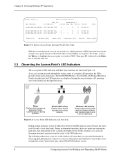
The Intel® PRO/Wireless 2011/2011B LAN Product Reference Guides describe how the LED indicators are : Functional and Send Probe. During an abnormal operation, the access point may be difficult to start the echo test. 3.3 Observing the Access Point's LED Indicators The access point's LED indicators and their basic functions are shown in a particular state permanently or for only a very short...
The Intel® PRO/Wireless 2011/2011B LAN Product Reference Guides describe how the LED indicators are : Functional and Send Probe. During an abnormal operation, the access point may be difficult to start the echo test. 3.3 Observing the Access Point's LED Indicators The access point's LED indicators and their basic functions are shown in a particular state permanently or for only a very short...
Configuration Guide
Page 17
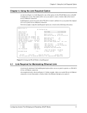
... and Repeating (WLAP Mode) 11 Link Required can also be used to allow WLAPs to roam to operate as a WLAP if it resets then makes a wireless link to the Ethernet through access point A. Figure 4-1: Setting the WLAP Mode to Link Required 4.1 Link Required for the WLAP Mode entry on the RF Configuration screen. Chapter...
... and Repeating (WLAP Mode) 11 Link Required can also be used to allow WLAPs to roam to operate as a WLAP if it resets then makes a wireless link to the Ethernet through access point A. Figure 4-1: Setting the WLAP Mode to Link Required 4.1 Link Required for the WLAP Mode entry on the RF Configuration screen. Chapter...
Configuration Guide
Page 18
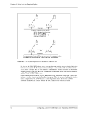
... State as DIS (disabled), and the WLAP Itf MAC Addr as the MAC address of the access points in the network in Figure 4-2, no wireless link exists between access points. A B Ethernet If an access point loses its Ethernet connection, it resets and makes a wireless link to the Ethernet. Ethernet Timeout = 0. Using the Link Required Option A B Ethernet Settings on Both...
... State as DIS (disabled), and the WLAP Itf MAC Addr as the MAC address of the access points in the network in Figure 4-2, no wireless link exists between access points. A B Ethernet If an access point loses its Ethernet connection, it resets and makes a wireless link to the Ethernet. Ethernet Timeout = 0. Using the Link Required Option A B Ethernet Settings on Both...
Configuration Guide
Page 19
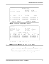
... Refresh-[F1] Timed-[F2] Previous-[F4] Exit-[ESC] Figure 4-4: Wireless Link After Loss of Ethernet Connection 4.2 Link Required for root access point A. When access point A's Ethernet connection is restored, WLAPs B and C roams back to access point D. In Figure 4-5, access points B and C are initially the designated WLAPs for Backing Up Root Access Point This section shows how to use the Link Required...
... Refresh-[F1] Timed-[F2] Previous-[F4] Exit-[ESC] Figure 4-4: Wireless Link After Loss of Ethernet Connection 4.2 Link Required for root access point A. When access point A's Ethernet connection is restored, WLAPs B and C roams back to access point D. In Figure 4-5, access points B and C are initially the designated WLAPs for Backing Up Root Access Point This section shows how to use the Link Required...
Configuration Guide
Page 25
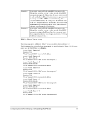
... WLAP-Alive BPDU messages on the Ethernet line, the access point resets. If the BPDU message is missing on the Ethernet line as well as over the wireless network. An example network using this setting is 20 seconds. Timeout = 0 Priority = 9000 WLAP Manual BSS ID = MAC address of ...radio and stops flashing the LED indicator. The following are the settings for an Ethernet 10BaseT cross-over the wireless network. Timeout = 1 Priority = 7000 WLAP Manual BSS ID = its own MAC address Access Point H. Timeout = 2 Priority = 8000 (default) WLAP Manual BSS ID = MAC address of the WLAP ...
... WLAP-Alive BPDU messages on the Ethernet line, the access point resets. If the BPDU message is missing on the Ethernet line as well as over the wireless network. An example network using this setting is 20 seconds. Timeout = 0 Priority = 9000 WLAP Manual BSS ID = MAC address of ...radio and stops flashing the LED indicator. The following are the settings for an Ethernet 10BaseT cross-over the wireless network. Timeout = 1 Priority = 7000 WLAP Manual BSS ID = its own MAC address Access Point H. Timeout = 2 Priority = 8000 (default) WLAP Manual BSS ID = MAC address of the WLAP ...
Configuration Guide
Page 27
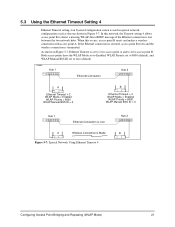
...Priority = 8000 WLAP Manual BSS ID = 0 Hub 1 Ethernet Connection is Lost A Wireless Connection is lost between the two network hubs. In this occurs, access point B resets and makes a wireless connection with access point A. As shown in Figure 5-7, Ethernet Timeout is used in special network configurations such as... 4 on System Configuration screen is set to zero (default). If the Ethernet connection is restored, access point B resets and the wireless connection is terminated. Both access points have the WLAP Mode set to Enabled, WLAP Priority set to 8000 (default), and WLAP Manual ...
...Priority = 8000 WLAP Manual BSS ID = 0 Hub 1 Ethernet Connection is Lost A Wireless Connection is lost between the two network hubs. In this occurs, access point B resets and makes a wireless connection with access point A. As shown in Figure 5-7, Ethernet Timeout is used in special network configurations such as... 4 on System Configuration screen is set to zero (default). If the Ethernet connection is restored, access point B resets and the wireless connection is terminated. Both access points have the WLAP Mode set to Enabled, WLAP Priority set to 8000 (default), and WLAP Manual ...
Configuration Guide
Page 38
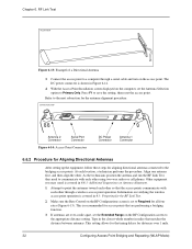
... a Directional Antenna 3. The DC power connector is set to a computer through a wireless access point operation. If antennas are performing a bridging function. 3. Type in the closest whole number in 6.6.3: Additional Suggestions on the access point. Connect the access point to Required for the RF Link Test. 2. Chapter 6. Other equipment you may need to save the setting, then reset the access point.
... a Directional Antenna 3. The DC power connector is set to a computer through a wireless access point operation. If antennas are performing a bridging function. 3. Type in the closest whole number in 6.6.3: Additional Suggestions on the access point. Connect the access point to Required for the RF Link Test. 2. Chapter 6. Other equipment you may need to save the setting, then reset the access point.
Configuration Guide
Page 39
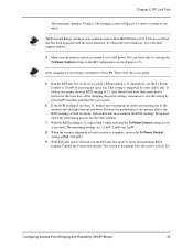
... the Tx Power Control setting on the RF Configuration screen (Figure 6-15). If the RSSI reading is only available with an Intel PRO/Wireless 2011 LAN Access Point that has been upgraded with the latest firmware. If required, repeat the positioning process for the other antenna. 7. With full ... Extended Range setting is less than 31, bring it up and down. You can verify this by pressing F1 and then resetting the access point. 6. Then, reset the access point. 5. To obtain the latest firmware, go to verify the maximum RSSI reading. Capture the Connection Quality Test screen to Press...
... the Tx Power Control setting on the RF Configuration screen (Figure 6-15). If the RSSI reading is only available with an Intel PRO/Wireless 2011 LAN Access Point that has been upgraded with the latest firmware. If required, repeat the positioning process for the other antenna. 7. With full ... Extended Range setting is less than 31, bring it up and down. You can verify this by pressing F1 and then resetting the access point. 6. Then, reset the access point. 5. To obtain the latest firmware, go to verify the maximum RSSI reading. Capture the Connection Quality Test screen to Press...