User Manual
Page 3
... and Software Required 23 Setting up the Evaluation Board 24 Memory Configurations 25 Audio Subsystem Configurations 28 LAN Subsystem Configurations 29 Intel® Active Management Technology (Optional 31 Configuring the BIOS...32 Error Messages and Beep Codes 32 Speaker ...32 BIOS Beep Codes ...32 BIOS Error Messages...33 Port 80h POST Codes...33 Hardware References...38 Overview...38 Board Layout...39 Back Panel Connectors 41 Primary Features...41 Core Components ...42 Expansion Slots and Sockets 42 Secondary Features ...46 Jumper Settings ...47 LEDs...47 Front Panel Header (Power...
... and Software Required 23 Setting up the Evaluation Board 24 Memory Configurations 25 Audio Subsystem Configurations 28 LAN Subsystem Configurations 29 Intel® Active Management Technology (Optional 31 Configuring the BIOS...32 Error Messages and Beep Codes 32 Speaker ...32 BIOS Beep Codes ...32 BIOS Error Messages...33 Port 80h POST Codes...33 Hardware References...38 Overview...38 Board Layout...39 Back Panel Connectors 41 Primary Features...41 Core Components ...42 Expansion Slots and Sockets 42 Secondary Features ...46 Jumper Settings ...47 LEDs...47 Front Panel Header (Power...
User Manual
Page 4
... 4.4.2 4.4.3 4.4.4 4.4.5 4.4.6 4.4.7 4.4.8 4.4.9 4.5 Evaluation Board Headers 48 ATX Power Connectors 49 IDE Connector...50 SATA Pinout ...50 Fan Connectors...51 Front Panel USB Header 51 Front Panel Audio Header 51 Front Panel Header ...52 Serial Port Header...52 Thermal Considerations 53 Figures Figure 1 Figure 2 Figure 3 Figure 4 Figure 5 Figure 6 Figure 7 Figure 8 Figure 9 Figure 10 Figure 11 Figure 12 Figure 13 Figure 14 Figure 15 Figure 16 Intel® 945G/ICH7 Platform Block Diagram 11 Memory Channel and DIMM Configuration 27 Dual Channel (Interleaved) Mode Configuration with...
... 4.4.2 4.4.3 4.4.4 4.4.5 4.4.6 4.4.7 4.4.8 4.4.9 4.5 Evaluation Board Headers 48 ATX Power Connectors 49 IDE Connector...50 SATA Pinout ...50 Fan Connectors...51 Front Panel USB Header 51 Front Panel Audio Header 51 Front Panel Header ...52 Serial Port Header...52 Thermal Considerations 53 Figures Figure 1 Figure 2 Figure 3 Figure 4 Figure 5 Figure 6 Figure 7 Figure 8 Figure 9 Figure 10 Figure 11 Figure 12 Figure 13 Figure 14 Figure 15 Figure 16 Intel® 945G/ICH7 Platform Block Diagram 11 Memory Channel and DIMM Configuration 27 Dual Channel (Interleaved) Mode Configuration with...
User Manual
Page 5
... 31 Table 32 Back Panel I/O Connectors 41 Core Components ...42 Expansion Slots and Sockets 42 Intel® sDVO to PCI Express* Connector Mapping for MEC Cards 43 PCI Express* (x1) Pinout 45 Jumpers ...47 Boot Select Options for J3601 and J3602 47 LEDs...47 Front Panel Jumper Setting 48 Evaluation Board Headers 48 2x12 ATX Power Connector 49 2x2 Auxiliary 12V Power Connector 49 IDE Connector...50 SATA Pinout ...50 Fan Connectors...51 Front Panel USB Header 51 Front Panel Audio Header 51 Front Panel Header (J7J2 52 Serial Port Header (J2B1 52 Revision...
... 31 Table 32 Back Panel I/O Connectors 41 Core Components ...42 Expansion Slots and Sockets 42 Intel® sDVO to PCI Express* Connector Mapping for MEC Cards 43 PCI Express* (x1) Pinout 45 Jumpers ...47 Boot Select Options for J3601 and J3602 47 LEDs...47 Front Panel Jumper Setting 48 Evaluation Board Headers 48 2x12 ATX Power Connector 49 2x2 Auxiliary 12V Power Connector 49 IDE Connector...50 SATA Pinout ...50 Fan Connectors...51 Front Panel USB Header 51 Front Panel Audio Header 51 Front Panel Header (J7J2 52 Serial Port Header (J2B1 52 Revision...
User Manual
Page 7
... Side Bus.Synonymous with an Intel graphics controller that supports DVO and ADD cards. they are collectively called CSn#. Intel® 945G Express Chipset Development Kit User's Manual About This Manual Units of Measure Signal Names The following abbreviations are used to a signal name identifies an active-low signal. Specification that supports ADD2+ cards. Term ADD2+ Card ACPI BLT Core CRT DBI DDR DDR2 DMI DVI FSB Full Reset Description Advanced Digital Display Card...
... Side Bus.Synonymous with an Intel graphics controller that supports DVO and ADD cards. they are collectively called CSn#. Intel® 945G Express Chipset Development Kit User's Manual About This Manual Units of Measure Signal Names The following abbreviations are used to a signal name identifies an active-low signal. Specification that supports ADD2+ cards. Term ADD2+ Card ACPI BLT Core CRT DBI DDR DDR2 DMI DVI FSB Full Reset Description Advanced Digital Display Card...
User Manual
Page 8
... external SDVO device. PCI Express is a high-speed serial interface whose configuration is a x16 link and replaces AGP. Serial Digital Video Out. Low Voltage Differential Signaling. Component that is not electrically compatible with processor. SDVO. This interface is driven directly by the ICH7 component. SMI is the physical PCI bus that contains the processor interface, DRAM controller, and x16 PCI Express port (typically, the external graphics interface). The Primary PCI is used for display connections to...
... external SDVO device. PCI Express is a high-speed serial interface whose configuration is a x16 link and replaces AGP. Serial Digital Video Out. Low Voltage Differential Signaling. Component that is not electrically compatible with processor. SDVO. This interface is driven directly by the ICH7 component. SMI is the physical PCI bus that contains the processor interface, DRAM controller, and x16 PCI Express port (typically, the external graphics interface). The Primary PCI is used for display connections to...
User Manual
Page 12
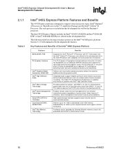
... peripheral devices and networking. High-speed storage interface supports faster transfer rate for additional discrete graphics cards. The following table lists the major features present on 90nm Process in the LGA775 socket, with scalability for faster system responsiveness and support of 64-bit computing. The PCI Express x1 I/O ports offer 3.5 times the bandwidth over a traditional AGP 8X interface and supports the latest high-performance graphics cards. Provides quicker file access with RAID...
... peripheral devices and networking. High-speed storage interface supports faster transfer rate for additional discrete graphics cards. The following table lists the major features present on 90nm Process in the LGA775 socket, with scalability for faster system responsiveness and support of 64-bit computing. The PCI Express x1 I/O ports offer 3.5 times the bandwidth over a traditional AGP 8X interface and supports the latest high-performance graphics cards. Provides quicker file access with RAID...
User Manual
Page 14
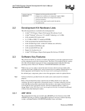
... in the kit is provided free by those products. Software included in the evaluation kit for updated drivers. Updated drivers for board power-on) • 1x Intel® 945G Express Chipset Development Kit Software CD-ROM Software Key Features The software in the kit was taken to ensure the latest version of drivers were provided on any terms and conditions that work with AMI BIOS pre-boot firmware from other third-party vendors...
... in the kit is provided free by those products. Software included in the evaluation kit for updated drivers. Updated drivers for board power-on) • 1x Intel® 945G Express Chipset Development Kit Software CD-ROM Software Key Features The software in the kit was taken to ensure the latest version of drivers were provided on any terms and conditions that work with AMI BIOS pre-boot firmware from other third-party vendors...
User Manual
Page 17
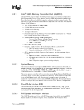
... to use up to Section 3.3.1, "Memory Configurations." The system memory controller will operate in -order queue • Processor support for an external PCI Express graphics card. In order to 1 Gbit technology for a maximum of the Intel 945G Express Chipset (G)MCH features. • 1202 FCBGA package (34 mm x 34 mm) • 533/800 MHz processor system bus • 32-bit host bus addressing • 12 deep in three modes: Single Channel, Dual Channel, and Virtual Single Channel. PCI Express* x16 Graphic Interface...
... to use up to Section 3.3.1, "Memory Configurations." The system memory controller will operate in -order queue • Processor support for an external PCI Express graphics card. In order to 1 Gbit technology for a maximum of the Intel 945G Express Chipset (G)MCH features. • 1202 FCBGA package (34 mm x 34 mm) • 533/800 MHz processor system bus • 32-bit host bus addressing • 12 deep in three modes: Single Channel, Dual Channel, and Virtual Single Channel. PCI Express* x16 Graphic Interface...

User Manual
Page 18
... Graphics Attach, compatible to support external graphics accelerators via the PCI Express Graphics (PEG) port but cannot work concurrently with two Intel® SDVO ports. This mechanism accesses the device configuration space in hardware reduces processor load, and thus improves performance. 18 Reference #308823 The (G)MCH also has the capability to the PCI Express Base Specification, Revision 1.0a. • A base PCI Express frequency of 2.5 Gbits/s only. • Raw bit-rate on the data pins...
... Graphics Attach, compatible to support external graphics accelerators via the PCI Express Graphics (PEG) port but cannot work concurrently with two Intel® SDVO ports. This mechanism accesses the device configuration space in hardware reduces processor load, and thus improves performance. 18 Reference #308823 The (G)MCH also has the capability to the PCI Express Base Specification, Revision 1.0a. • A base PCI Express frequency of 2.5 Gbits/s only. • Raw bit-rate on the data pins...
User Manual
Page 19
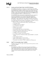
... and Serial Digital Video Out (SDVO) Displays The (G)MCH provides interfaces to a progressive scan analog monitor and two SDVO ports (multiplexed with PCI Express x16 graphics port signals) capable of driving up to -chip connection between the Memory Controller Hub / Graphics Memory Controller Hub ((G)MCH) and I /O support. The (G)MCH provides two multiplexed SDVO ports that SDVO only works with a DVI-compliant external device and connector, the (G)MCH has a high-speed interface to support dual channel devices, supporting higher resolutions...
... and Serial Digital Video Out (SDVO) Displays The (G)MCH provides interfaces to a progressive scan analog monitor and two SDVO ports (multiplexed with PCI Express x16 graphics port signals) capable of driving up to -chip connection between the Memory Controller Hub / Graphics Memory Controller Hub ((G)MCH) and I /O support. The (G)MCH provides two multiplexed SDVO ports that SDVO only works with a DVI-compliant external device and connector, the (G)MCH has a high-speed interface to support dual channel devices, supporting higher resolutions...
User Manual
Page 20
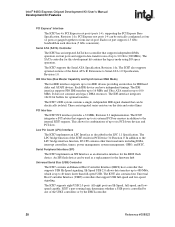
... series resistors on four ports and supports data transfer rates of the UHCI controllers or by one x4 port. ICH7's port-routing logic determines whether a USB port is up to the internal ICH7 requests. Intel® 945G Express Chipset Development Kit User's Manual Development Kit Features PCI Express* Interface The ICH7 has 4x PCI Express root ports (ports 1-4), supporting the PCI Express Base Specification, Revision 1.0a. IDE Interface (Bus Master Capability and Synchronous DMA Mode) The fast IDE interface supports...
... series resistors on four ports and supports data transfer rates of the UHCI controllers or by one x4 port. ICH7's port-routing logic determines whether a USB port is up to the internal ICH7 requests. Intel® 945G Express Chipset Development Kit User's Manual Development Kit Features PCI Express* Interface The ICH7 has 4x PCI Express root ports (ports 1-4), supporting the PCI Express Base Specification, Revision 1.0a. IDE Interface (Bus Master Capability and Synchronous DMA Mode) The fast IDE interface supports...
User Manual
Page 21
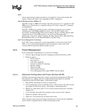
... technology ⎯ Resume on Ring ⎯ Wake from USB ⎯ Wake from PS/2 Devices ⎯ Power Management Event signal (PME#) wake-up events • Support for a front panel power and sleep mode switch Table 5 lists the system states based on how long the power switch is pressed, depending on ICH7 configuration. The number of a computer. The ICH7's SMBus host controller provides a mechanism for custom system design. Intel® 945G Express Chipset Development Kit User's Manual...
... technology ⎯ Resume on Ring ⎯ Wake from USB ⎯ Wake from PS/2 Devices ⎯ Power Management Event signal (PME#) wake-up events • Support for a front panel power and sleep mode switch Table 5 lists the system states based on how long the power switch is pressed, depending on ICH7 configuration. The number of a computer. The ICH7's SMBus host controller provides a mechanism for custom system design. Intel® 945G Express Chipset Development Kit User's Manual...

User Manual
Page 23
... proper video settings. The setup instructions in changing hardware configuration and peripherals. Mouse You will need a PS/2 style or USB mouse. Check the BIOS for the board layout, jumper setting location, and the component reference designator. 3.1 Note: Overview The evaluation board consists of the system board. The evaluation board is shipped as necessary. No drives or cables are using a standard VGA monitor. All the storage devices may be used . VGA Monitor You can connect up and operation. Keyboard...
... proper video settings. The setup instructions in changing hardware configuration and peripherals. Mouse You will need a PS/2 style or USB mouse. Check the BIOS for the board layout, jumper setting location, and the component reference designator. 3.1 Note: Overview The evaluation board consists of the system board. The evaluation board is shipped as necessary. No drives or cables are using a standard VGA monitor. All the storage devices may be used . VGA Monitor You can connect up and operation. Keyboard...
User Manual
Page 24
... device being connected. Note: To locate items discussed in a static-free environment before removing any components from their anti-static packaging. Create a safe work with a minimum of your kit. Standby voltage is constantly applied to the evaluation board. Check the jumper settings (refer to clear the CMOS memory. Intel® 945G Express Chipset Development Kit User's Manual Setting Up the Development Kit Power Supply The evaluation board requires the use caution when connecting cables to this jumper is set...
... device being connected. Note: To locate items discussed in a static-free environment before removing any components from their anti-static packaging. Create a safe work with a minimum of your kit. Standby voltage is constantly applied to the evaluation board. Check the jumper settings (refer to clear the CMOS memory. Intel® 945G Express Chipset Development Kit User's Manual Setting Up the Development Kit Power Supply The evaluation board requires the use caution when connecting cables to this jumper is set...
User Manual
Page 25
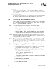
... ATX power supply to the floppy drive. 9. Insert the ATX board connector of the ribbon cable to the monitor and evaluation board. After connecting the power supply board connectors, plug the power supply cord into electrical outlet turned off). Turn on the baseboard) is a stacked PS/2 connector. If different speed DIMMs are unequal. Technology and device width can vary from one channel to the other . Connect a power cable to the evaluation board. Make sure the power supply is operating. 3.3.1 Memory Configurations The Intel® 945G MCH supports...
... ATX power supply to the floppy drive. 9. Insert the ATX board connector of the ribbon cable to the monitor and evaluation board. After connecting the power supply board connectors, plug the power supply cord into electrical outlet turned off). Turn on the baseboard) is a stacked PS/2 connector. If different speed DIMMs are unequal. Technology and device width can vary from one channel to the other . Connect a power cable to the evaluation board. Make sure the power supply is operating. 3.3.1 Memory Configurations The Intel® 945G MCH supports...
User Manual
Page 32
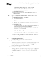
... speaker provides audible error code (beep code) information during POST, the BIOS "beeps" as described in the following table. Intel® 945G Express Chipset Development Kit User's Manual Setting Up the Development Kit 3.3.5 3.4 3.4.1 3.4.2 Table 8 ⎯ Operating system lock-up . You can use the setup program to Figure 11. For information about the location of the onboard speaker refer to modify BIOS settings and control special features of the system. You may be posted to enable hard disks, floppy disks...
... speaker provides audible error code (beep code) information during POST, the BIOS "beeps" as described in the following table. Intel® 945G Express Chipset Development Kit User's Manual Setting Up the Development Kit 3.3.5 3.4 3.4.1 3.4.2 Table 8 ⎯ Operating system lock-up . You can use the setup program to Figure 11. For information about the location of the onboard speaker refer to modify BIOS settings and control special features of the system. You may be posted to enable hard disks, floppy disks...
User Manual
Page 33
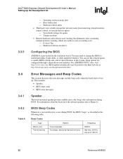
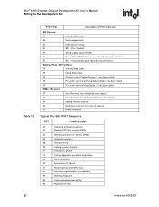
... devices: Keyboard/Mouse. 9F is no memory detected or no memory was removed, then memory may be used by the BIOS: POST code ranges, the POST codes themselves, and the POST sequence. Intel® 945G Express Chipset Development Kit User's Manual Setting Up the Development Kit 3.4.3 Table 9 BIOS Error Messages The table below show the lists of BIOS error messages and brief description of each. Memory/Chipset: 2F is an unrecoverable error. Boot device selection. Error Messages Error Message CMOS Battery Low CMOS Checksum Bad Memory Size...
... devices: Keyboard/Mouse. 9F is no memory detected or no memory was removed, then memory may be used by the BIOS: POST code ranges, the POST codes themselves, and the POST sequence. Intel® 945G Express Chipset Development Kit User's Manual Setting Up the Development Kit 3.4.3 Table 9 BIOS Error Messages The table below show the lists of BIOS error messages and brief description of each. Memory/Chipset: 2F is an unrecoverable error. Boot device selection. Error Messages Error Message CMOS Battery Low CMOS Checksum Bad Memory Size...
User Manual
Page 36
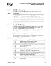
...called . PEIMs / Recovery 30 Crisis Recovery has initiated per user request. 31 Crisis Recovery has initiated by software (corrupt flash). 34 Loading recovery capsule. 35 Handing off control to the recovery capsule. 3F Unable to PCI bus. Starting Application processor initialization. SMM initialization. Intel® 945G Express Chipset Development Kit User's Manual Setting Up the Development Kit Table 12 POST Code Description of memory DIMMs. Configuring memory. F5 Exiting Sleep state. Resetting keyboard. E8 Checking password. EB Calling Legacy Option ROMs. EE TBD...
...called . PEIMs / Recovery 30 Crisis Recovery has initiated per user request. 31 Crisis Recovery has initiated by software (corrupt flash). 34 Loading recovery capsule. 35 Handing off control to the recovery capsule. 3F Unable to PCI bus. Starting Application processor initialization. SMM initialization. Intel® 945G Express Chipset Development Kit User's Manual Setting Up the Development Kit Table 12 POST Code Description of memory DIMMs. Configuring memory. F5 Exiting Sleep state. Resetting keyboard. E8 Checking password. EB Calling Legacy Option ROMs. EE TBD...
User Manual
Page 41
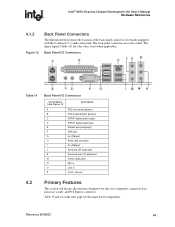
... (Table 14) lists the colors used (when applicable). Reference #308823 41 Intel® 945G Express Chipset Development Kit User's Manual Hardware References 4.1.2 Figure 12 Back Panel Connectors The illustration below shows the location of the back panel connectors for the core component, expansion slots, processor socket, and PCI Express connector. The back panel connectors are color-coded. Back Panel I/O Connectors Table 14 Back Panel I/O Connectors Item/Callout from Figure 12 A B C D E F G H I J K M N O P Description PS/2 mouse port [green] PS/2 keyboard port [purple] S/PDIF...
... (Table 14) lists the colors used (when applicable). Reference #308823 41 Intel® 945G Express Chipset Development Kit User's Manual Hardware References 4.1.2 Figure 12 Back Panel Connectors The illustration below shows the location of the back panel connectors for the core component, expansion slots, processor socket, and PCI Express connector. The back panel connectors are color-coded. Back Panel I/O Connectors Table 14 Back Panel I/O Connectors Item/Callout from Figure 12 A B C D E F G H I J K M N O P Description PS/2 mouse port [green] PS/2 keyboard port [purple] S/PDIF...
User Manual
Page 47
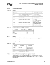
... core power is a CPU installed so user can power up and board reset. Please refer to Table 20 for details: Populate jumper means "0". Clear CMOS jumper Config mode jumper and BIOS recovery jumper Boot method jumpers selection (GNT5) Boot method jumpers selection (GNT4) Comments (default settings in device or board damage. Refer to the planes. Boot Select Options for J3601 and J3602 Boot Select SPI PCI LPC (FWH) GNT5 (J3601) 0 1 1 GNT4 (J3602) 1 0 1 4.3.2 LEDs Power LEDs are on could result in bold) 1-2 Normal operation 2-3 Clocks...
... core power is a CPU installed so user can power up and board reset. Please refer to Table 20 for details: Populate jumper means "0". Clear CMOS jumper Config mode jumper and BIOS recovery jumper Boot method jumpers selection (GNT5) Boot method jumpers selection (GNT4) Comments (default settings in device or board damage. Refer to the planes. Boot Select Options for J3601 and J3602 Boot Select SPI PCI LPC (FWH) GNT5 (J3601) 0 1 1 GNT4 (J3602) 1 0 1 4.3.2 LEDs Power LEDs are on could result in bold) 1-2 Normal operation 2-3 Clocks...


