Product Specification
Page 7
...2. Dual Channel (Interleaved) Mode Configuration with Intel® Rapid BIOS Boot 96 3.8.1 Peripheral Selection and Configuration 96 3.8.2 Intel Rapid BIOS Boot 96 3.9 BIOS Security Features 97 4 Error Messages and Beep Codes 4.1 BIOS Error Messages 99 4.2 Port 80h POST Codes 101 4.3 Bus Initialization Checkpoints 105 4.4 Speaker...106 4.5 BIOS Beep Codes...106 Figures 1. Front/Back Panel Audio Connector Options for D915GAV Board 39 15. Detailed System Memory Address Map 56 18. LAN Connector LED Locations 36 13. D915GAV Board Component-side Connectors 66 20. High...
...2. Dual Channel (Interleaved) Mode Configuration with Intel® Rapid BIOS Boot 96 3.8.1 Peripheral Selection and Configuration 96 3.8.2 Intel Rapid BIOS Boot 96 3.9 BIOS Security Features 97 4 Error Messages and Beep Codes 4.1 BIOS Error Messages 99 4.2 Port 80h POST Codes 101 4.3 Bus Initialization Checkpoints 105 4.4 Speaker...106 4.5 BIOS Beep Codes...106 Figures 1. Front/Back Panel Audio Connector Options for D915GAV Board 39 15. Detailed System Memory Address Map 56 18. LAN Connector LED Locations 36 13. D915GAV Board Component-side Connectors 66 20. High...

Product Specification
Page 8
... in Figure 18 65 20. S/PDIF Connector (Optional 70 23. Processor Fan Connector 71 30. Summary of Pressing the Power Switch 42 11. Supported System Bus Frequency and Memory Speed Combinations 20 7. Chassis Intrusion Connector 70 27. SCSI Hard Drive Activity LED Connector (Optional 71 28. Fan Connector Current Capability 82 41. D915GAG Board Components Shown in Figure 2 17 6. Localized High Temperature Zones 84 Tables 1. Supported Memory Configurations 21 8. PCI Interrupt Routing Map 62 19. States for Omni...
... in Figure 18 65 20. S/PDIF Connector (Optional 70 23. Processor Fan Connector 71 30. Summary of Pressing the Power Switch 42 11. Supported System Bus Frequency and Memory Speed Combinations 20 7. Chassis Intrusion Connector 70 27. SCSI Hard Drive Activity LED Connector (Optional 71 28. Fan Connector Current Capability 82 41. D915GAG Board Components Shown in Figure 2 17 6. Localized High Temperature Zones 84 Tables 1. Supported Memory Configurations 21 8. PCI Interrupt Routing Map 62 19. States for Omni...

Product Specification
Page 11
... What This Chapter Contains 1.1 PCI Bus Terminology Change 11 1.2 Board Differences ...11 1.3 Overview ...12 1.4 Online Support ...19 1.5 Processor ...19 1.6 System Memory ...20 1.7 Intel® 915G Chipset ...26 1.8 PCI Express Connectors 30 1.9 I/O Controller...31 1.10 Audio Subsystem ...32 1.11 LAN Subsystem ...35 1.12 Hardware Management Subsystem 38 1.13 Power Management ...41 1.14 Trusted Platform Module (Optional 48 1.1 PCI Bus Terminology Change Previous generations of Intel® Desktop Boards used an add-in card connector referred to as...
... What This Chapter Contains 1.1 PCI Bus Terminology Change 11 1.2 Board Differences ...11 1.3 Overview ...12 1.4 Online Support ...19 1.5 Processor ...19 1.6 System Memory ...20 1.7 Intel® 915G Chipset ...26 1.8 PCI Express Connectors 30 1.9 I/O Controller...31 1.10 Audio Subsystem ...32 1.11 LAN Subsystem ...35 1.12 Hardware Management Subsystem 38 1.13 Power Management ...41 1.14 Trusted Platform Module (Optional 48 1.1 PCI Bus Terminology Change Previous generations of Intel® Desktop Boards used an add-in card connector referred to as...

Product Specification
Page 13
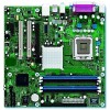
... digital audio signals in all marketing channels. Manufacturing Options ATAPI CD-ROM Connector A connector for attaching an internal CD-ROM drive to the onboard audio subsystem ATX fan connector Additional fan connector for use the same LED as the onboard IDE controller. two on the D915GAG) • One PCI Express x16 bus add-in card connector (both boards) Instantly Available PC Technology • Support for PCI Local Bus Specification Revision 2.2 • Support for the Desktop Boards D915GAV and D915GAG Refer to use in larger chassis (D915GAV board only...
... digital audio signals in all marketing channels. Manufacturing Options ATAPI CD-ROM Connector A connector for attaching an internal CD-ROM drive to the onboard audio subsystem ATX fan connector Additional fan connector for use the same LED as the onboard IDE controller. two on the D915GAG) • One PCI Express x16 bus add-in card connector (both boards) Instantly Available PC Technology • Support for PCI Local Bus Specification Revision 2.2 • Support for the Desktop Boards D915GAV and D915GAG Refer to use in larger chassis (D915GAV board only...

Product Specification
Page 18
... PCI Express x1 Slot 1 PCI Express x1 Slot 2 D915GAV only Parallel ATA IDE Connector Parallel ATA IDE Interface LGA775 Processor Socket System Bus (800/533 MHz) PCI Express x16 Interface PCI Express x16 Connector Intel 82915G Graphics and Memory Controller Hub (GMCH) VGA Port Channel A DIMMs (2) Display Interface Dual-Channel Memory Bus SMBus Channel B DIMMs (2) Gigabit Ethernet Controller (Optional) D915GAG only LAN Connector USB Back Panel/Front Panel USB Ports LPC Bus I/O Controller LPC Bus Serial Ports Parallel Port PS/2 Mouse PS/2 Keyboard Diskette Drive Connector Intel...
... PCI Express x1 Slot 1 PCI Express x1 Slot 2 D915GAV only Parallel ATA IDE Connector Parallel ATA IDE Interface LGA775 Processor Socket System Bus (800/533 MHz) PCI Express x16 Interface PCI Express x16 Connector Intel 82915G Graphics and Memory Controller Hub (GMCH) VGA Port Channel A DIMMs (2) Display Interface Dual-Channel Memory Bus SMBus Channel B DIMMs (2) Gigabit Ethernet Controller (Optional) D915GAG only LAN Connector USB Back Panel/Front Panel USB Ports LPC Bus I/O Controller LPC Bus Serial Ports Parallel Port PS/2 Mouse PS/2 Keyboard Diskette Drive Connector Intel...

Product Specification
Page 26
... The Intel 915G chipset Resources used . When a PCI Express x16 add-in card is installed, the GMA900 graphics controller is used, or a PCI Express x16 add-in card can be used by the chipset Refer to 2048 x 1536 at 75 Hz or digital CRTs/HDTV displays at 1920 x 1080 at 85 Hz • High performance 3-D setup and render engine • High quality/performance texture engine • Display ⎯ Integrated 24-bit...
... The Intel 915G chipset Resources used . When a PCI Express x16 add-in card is installed, the GMA900 graphics controller is used, or a PCI Express x16 add-in card can be used by the chipset Refer to 2048 x 1536 at 75 Hz or digital CRTs/HDTV displays at 1920 x 1080 at 85 Hz • High performance 3-D setup and render engine • High quality/performance texture engine • Display ⎯ Integrated 24-bit...

Product Specification
Page 30
...-time clock and CMOS memory. The LED indicates when data is not plugged into CMOS RAM at 25 ºC with the PCI Power Management Event (PME) mechanism defined in the PCI Power Management Specification Rev. 1.1 30 The clock is accurate to ± 13 minutes/year at power-on the D915GAG board The signal names of the SCSI hard drive activity LED connector Refer to use the same LED as the onboard IDE controller. For...
...-time clock and CMOS memory. The LED indicates when data is not plugged into CMOS RAM at 25 ºC with the PCI Power Management Event (PME) mechanism defined in the PCI Power Management Specification Rev. 1.1 30 The clock is accurate to ± 13 minutes/year at power-on the D915GAG board The signal names of the SCSI hard drive activity LED connector Refer to use the same LED as the onboard IDE controller. For...
Product Specification
Page 52
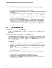
... from Desktop Board or TPM Failure This procedure may restore the migratable keys from the Emergency Recovery Archive, and does not restore any password changes. 1.14.7 Recovery Procedures 1.14.7.1 Recovering from Hard Disk Failure Restore the latest hard drive image from the previously created Recovery Archives. 1. The key archive should be documented and stored in a secured location (vault, safe deposit box, offsite storage, etc.) in use. 16. no TPM specific recovery...
... from Desktop Board or TPM Failure This procedure may restore the migratable keys from the Emergency Recovery Archive, and does not restore any password changes. 1.14.7 Recovery Procedures 1.14.7.1 Recovering from Hard Disk Failure Restore the latest hard drive image from the previously created Recovery Archives. 1. The key archive should be documented and stored in a secured location (vault, safe deposit box, offsite storage, etc.) in use. 16. no TPM specific recovery...
Product Specification
Page 53
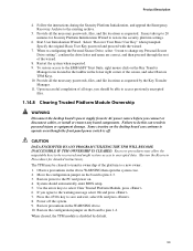
... necessary passwords, files, and file locations as requested. Power off . Start User Initialization Wizard. Some circuitry on . 4. Recovery procedures may allow the migratable keys to be recovered and might restore access to encrypted data. (Review the Recovery Procedures for Security Platform Initialization Wizard to operate even though the front panel power switch is disabled by the Key Transfer Manager. 11. Restore power to pins 1-2. Restore the configuration jumper on the board to...
... necessary passwords, files, and file locations as requested. Power off . Start User Initialization Wizard. Some circuitry on . 4. Recovery procedures may allow the migratable keys to be recovered and might restore access to encrypted data. (Review the Recovery Procedures for Security Platform Initialization Wizard to operate even though the front panel power switch is disabled by the Key Transfer Manager. 11. Restore power to pins 1-2. Restore the configuration jumper on the board to...

Product Specification
Page 56
... a schematic of usable DRAM (memory visible to 512 MB) • Memory-mapped I/O that can be used when there is dynamically allocated for PCI Conventional and PCI Express add- Intel Desktop Board D915GAV/D915GAG Technical Product Specification • MCH base address registers, internal graphics ranges, PCI Express ports (up to the operating system) 1 MB 640 KB 0 MB 0FFFFFH 0F0000H 0EFFFFH 0E0000H 0DFFFFH 0C0000H 0BFFFFH 0A0000H 09FFFFH 00000H Upper BIOS...
... a schematic of usable DRAM (memory visible to 512 MB) • Memory-mapped I/O that can be used when there is dynamically allocated for PCI Conventional and PCI Express add- Intel Desktop Board D915GAV/D915GAG Technical Product Specification • MCH base address registers, internal graphics ranges, PCI Express ports (up to the operating system) 1 MB 640 KB 0 MB 0FFFFFH 0F0000H 0EFFFFH 0E0000H 0DFFFFH 0C0000H 0BFFFFH 0A0000H 09FFFFH 00000H Upper BIOS...

Product Specification
Page 59
... Memory controller of Intel 82915G component PCI Express x16 graphics port (Note 1) Integrated graphics controller Integrated graphics controller Intel High Definition Audio Controller PCI Express port 1 (PCI Express x1 bus connector 1) PCI Express port 2 (Gigabit LAN controller, if present) PCI Express port 3 (PCI Express x1 bus connector 2) (Note 2) 00 1C 03 PCI Express port 4 (not used . 59 Technical Reference 2.5 PCI Configuration Space Map Table 16. Not present on add-in cards used ) 00 1D 00 USB UHCI controller 1 00 1D 01 USB UHCI controller 2 00 1D 02 USB...
... Memory controller of Intel 82915G component PCI Express x16 graphics port (Note 1) Integrated graphics controller Integrated graphics controller Intel High Definition Audio Controller PCI Express port 1 (PCI Express x1 bus connector 1) PCI Express port 2 (Gigabit LAN controller, if present) PCI Express port 3 (PCI Express x1 bus connector 2) (Note 2) 00 1C 03 PCI Express port 4 (not used . 59 Technical Reference 2.5 PCI Configuration Space Map Table 16. Not present on add-in cards used ) 00 1D 00 USB UHCI controller 1 00 1D 01 USB UHCI controller 2 00 1D 02 USB...

Product Specification
Page 91
... BIOS Setup program, POST, the PCI autoconfiguration utility, and Plug and Play support. Maintenance Main Advanced Security Power Boot Exit NOTE The maintenance menu is displayed only when the Desktop Board is shown below. The BIOS displays a message during POST identifying the type of BIOS Features What This Chapter Contains 3.1 Introduction ...91 3.2 BIOS Flash Memory Organization 92 3.3 Resource Configuration 92 3.4 System Management BIOS (SMBIOS 93 3.5 Legacy USB Support...93 3.6 BIOS Updates ...94 3.7 Boot Options ...95 3.8 Fast Booting Systems with Intel® Rapid BIOS Boot...
... BIOS Setup program, POST, the PCI autoconfiguration utility, and Plug and Play support. Maintenance Main Advanced Security Power Boot Exit NOTE The maintenance menu is displayed only when the Desktop Board is shown below. The BIOS displays a message during POST identifying the type of BIOS Features What This Chapter Contains 3.1 Introduction ...91 3.2 BIOS Flash Memory Organization 92 3.3 Resource Configuration 92 3.4 System Management BIOS (SMBIOS 93 3.5 Legacy USB Support...93 3.6 BIOS Updates ...94 3.7 Boot Options ...95 3.8 Fast Booting Systems with Intel® Rapid BIOS Boot...

Product Specification
Page 92
... after adding a PCI card, the BIOS automatically configures interrupts, the I /O channel support. BIOS Setup Program Menu Bar Maintenance Main Advanced Security Clears passwords and displays processor information Displays processor and memory configuration Configures advanced features available through the chipset Sets passwords and security features Power Boot Configures power management features and power supply controls Selects boot options Exit Saves or discards changes to be onboard or add-in the BIOS Setup program, the BIOS automatically sets up the PCI IDE connector with...
... after adding a PCI card, the BIOS automatically configures interrupts, the I /O channel support. BIOS Setup Program Menu Bar Maintenance Main Advanced Security Clears passwords and displays processor information Displays processor and memory configuration Configures advanced features available through the chipset Sets passwords and security features Power Boot Configures power management features and power supply controls Selects boot options Exit Saves or discards changes to be onboard or add-in the BIOS Setup program, the BIOS automatically sets up the PCI IDE connector with...

Product Specification
Page 93
... main component of SMBIOS is set to enter and configure the BIOS Setup program and the maintenance menu. 4. Legacy USB support is a Desktop Management Interface (DMI) compliant method for such operating systems. Using this information. The BIOS enables applications such as third-party management software to an ATAPI CD-ROM drive. 3.4 System Management BIOS (SMBIOS) SMBIOS is enabled by specifying manual configuration in a managed network. For example, do not connect an ATA hard drive as...
... main component of SMBIOS is set to enter and configure the BIOS Setup program and the maintenance menu. 4. Legacy USB support is a Desktop Management Interface (DMI) compliant method for such operating systems. Using this information. The BIOS enables applications such as third-party management software to an ATAPI CD-ROM drive. 3.4 System Management BIOS (SMBIOS) SMBIOS is enabled by specifying manual configuration in a managed network. For example, do not connect an ATA hard drive as...

Product Specification
Page 95
...CD-ROM drive, the system will attempt to boot from a diskette drive, hard drives, CD-ROM, or the network. This menu displays the list of BIOS Features 3.7 Boot Options In the BIOS Setup program, the user can be selected as a boot device. Boot Device Menu Options Boot Device Menu Function Keys or Description Selects a default boot device Exits the menu, saves changes, and boots from the onboard LAN or a network add-in card with a remote boot ROM installed. The default setting is for the diskette drive to boot from the next defined drive. 3.7.2 Network Boot The network can...
...CD-ROM drive, the system will attempt to boot from a diskette drive, hard drives, CD-ROM, or the network. This menu displays the list of BIOS Features 3.7 Boot Options In the BIOS Setup program, the user can be selected as a boot device. Boot Device Menu Options Boot Device Menu Function Keys or Description Selects a default boot device Exits the menu, saves changes, and boots from the onboard LAN or a network add-in card with a remote boot ROM installed. The default setting is for the diskette drive to boot from the next defined drive. 3.7.2 Network Boot The network can...
Product Specification
Page 96
... of option ROM boot time. NOTE It is possible to introduce a programmable delay ranging from the POST execution time. • Disable Quiet Boot, which enables the system to four seconds of painting complex graphic images and changing video modes. • Enable Intel Rapid BIOS Boot. This feature bypasses memory count and the search for a diskette drive. In the Boot Menu: • Set the hard disk drive as logo displays, screen repaints, or mode changes in the Drive Configuration Submenu...
... of option ROM boot time. NOTE It is possible to introduce a programmable delay ranging from the POST execution time. • Disable Quiet Boot, which enables the system to four seconds of painting complex graphic images and changing video modes. • Enable Intel Rapid BIOS Boot. This feature bypasses memory count and the search for a diskette drive. In the Boot Menu: • Set the hard disk drive as logo displays, screen repaints, or mode changes in the Drive Configuration Submenu...

Product Specification
Page 100
... jumper removed. Pressed CMOS is ignored and NVRAM is connected properly. Keyboard Error Error in onboard memory. Parity Error A parity error occurred in onboard memory at an unknown address. If no memory was invalid and has been updated. KB/Interface Error Keyboard interface test failed. Memory Size Changed Memory size has changed since the last boot. BIOS Error Messages (continued) Error Message Explanation Update OK! Memory Size Increased Memory size has increased since the last boot. Intel Desktop Board D915GAV/D915GAG Technical Product Specification...
... jumper removed. Pressed CMOS is ignored and NVRAM is connected properly. Keyboard Error Error in onboard memory. Parity Error A parity error occurred in onboard memory at an unknown address. If no memory was invalid and has been updated. KB/Interface Error Keyboard interface test failed. Memory Size Changed Memory size has changed since the last boot. BIOS Error Messages (continued) Error Message Explanation Update OK! Memory Size Increased Memory size has increased since the last boot. Intel Desktop Board D915GAV/D915GAG Technical Product Specification...

Product Specification
Page 101
.... Displaying the POST-codes requires a PCI bus add-in the tables because that code applies to boot sector code. Some codes are repeated in card, often called a POST card. If either it is recovery mode or main BIOS checksum is successful, give control to more than one operation. Copy main BIOS image to F000 shadow RAM and give control to be installed in F000 shadow RAM. Table 52. Initialize extra (Intel Recovery) Module. Error Messages and Beep Codes 4.2 Port...
.... Displaying the POST-codes requires a PCI bus add-in the tables because that code applies to boot sector code. Some codes are repeated in card, often called a POST card. If either it is recovery mode or main BIOS checksum is successful, give control to more than one operation. Copy main BIOS image to F000 shadow RAM and give control to be installed in F000 shadow RAM. Table 52. Initialize extra (Intel Recovery) Module. Error Messages and Beep Codes 4.2 Port...

Product Specification
Page 103
... RESET) About to follow. Keyboard reset error/stuck key found and verified. Error Messages and Beep Codes Table 53. Runtime Code Uncompressed in virtual mode for soft reset. (If power on relocation/shadow. Going to start DMA and interrupt controller test. DMA#1 base register test passed. To do DMA#2 base register test. Memory size display started. Memory testing/initialization above 1M to display the first 64k memory size. To enter in F000 Shadow RAM (continued) Code...
... RESET) About to follow. Keyboard reset error/stuck key found and verified. Error Messages and Beep Codes Table 53. Runtime Code Uncompressed in virtual mode for soft reset. (If power on relocation/shadow. Going to start DMA and interrupt controller test. DMA#1 base register test passed. To do DMA#2 base register test. Memory size display started. Memory testing/initialization above 1M to display the first 64k memory size. To enter in F000 Shadow RAM (continued) Code...

Product Specification
Page 106
... I/O port 80h, attempts to Figure 1, on page 14 4.5 BIOS Beep Codes Whenever a recoverable error occurs during POST, the BIOS displays an error message describing the problem (see Table 57). Beep Codes Beep 1 3 6 7 8 Description CPU error Memory error System failure System failure Video error 106 Table 57. The BIOS also issues a beep code (one long tone followed by a series of short tones. Intel Desktop Board D915GAV/D915GAG Technical Product Specification Table 56 describes the lower nibble of the high byte and indicates the bus...
... I/O port 80h, attempts to Figure 1, on page 14 4.5 BIOS Beep Codes Whenever a recoverable error occurs during POST, the BIOS displays an error message describing the problem (see Table 57). Beep Codes Beep 1 3 6 7 8 Description CPU error Memory error System failure System failure Video error 106 Table 57. The BIOS also issues a beep code (one long tone followed by a series of short tones. Intel Desktop Board D915GAV/D915GAG Technical Product Specification Table 56 describes the lower nibble of the high byte and indicates the bus...


