
Product Specification
Page 5
...Summary 12 1.3.2 Manufacturing Options 13 1.3.3 Board Layouts 14 1.3.4 Block Diagram 18 1.4 Online Support ...19 1.5 Processor ...19 1.6 System Memory ...20 1.6.1 Memory Configurations 22 1.7 Intel® 915G Chipset ...26 1.7.1 Intel 915G Graphics Subsystem 26 1.7.2 USB ...28 1.7.3 IDE Support 28 1.7.4 Real-Time Clock, CMOS SRAM, and...Keyboard and Mouse Interface 32 1.10 Audio Subsystem ...32 1.10.1 Audio Subsystem Software 33 1.10.2 Audio Connectors 33 1.10.3 Intel® High Definition Audio Subsystem 34 1.11 LAN Subsystem ...35 1.11.1 10/100 Mbits/sec LAN Subsystem 35 1.11.2 ...
...Summary 12 1.3.2 Manufacturing Options 13 1.3.3 Board Layouts 14 1.3.4 Block Diagram 18 1.4 Online Support ...19 1.5 Processor ...19 1.6 System Memory ...20 1.6.1 Memory Configurations 22 1.7 Intel® 915G Chipset ...26 1.7.1 Intel 915G Graphics Subsystem 26 1.7.2 USB ...28 1.7.3 IDE Support 28 1.7.4 Real-Time Clock, CMOS SRAM, and...Keyboard and Mouse Interface 32 1.10 Audio Subsystem ...32 1.10.1 Audio Subsystem Software 33 1.10.2 Audio Connectors 33 1.10.3 Intel® High Definition Audio Subsystem 34 1.11 LAN Subsystem ...35 1.11.1 10/100 Mbits/sec LAN Subsystem 35 1.11.2 ...

Product Specification
Page 8
Intel Desktop Board D915GAV/D915GAG Technical Product Specification 27. Summary of Pressing ...-side Connectors Shown in Figure 19 67 21. S/PDIF Connector (Optional 70 23. Chassis Intrusion Connector 70 27. Processor Fan Connector 71 30. ATX12V Power Connector 73 33. States for Components 85 42. Fan Connector Current Capability 82 41... 7. PCI Configuration Space Map 59 17. Serial Port B Connector (optional 70 26. Serial ATA Connectors 71 29. Processor Heatsink for a One-Color Power LED 75 37. I /O Shield Dimensions 80 28. Auxiliary Front Panel Power/Sleep LED...
Intel Desktop Board D915GAV/D915GAG Technical Product Specification 27. Summary of Pressing ...-side Connectors Shown in Figure 19 67 21. S/PDIF Connector (Optional 70 23. Chassis Intrusion Connector 70 27. Processor Fan Connector 71 30. ATX12V Power Connector 73 33. States for Components 85 42. Fan Connector Current Capability 82 41... 7. PCI Configuration Space Map 59 17. Serial Port B Connector (optional 70 26. Serial ATA Connectors 71 29. Processor Heatsink for a One-Color Power LED 75 37. I /O Shield Dimensions 80 28. Auxiliary Front Panel Power/Sleep LED...

Product Specification
Page 11
...Description What This Chapter Contains 1.1 PCI Bus Terminology Change 11 1.2 Board Differences ...11 1.3 Overview ...12 1.4 Online Support ...19 1.5 Processor ...19 1.6 System Memory ...20 1.7 Intel® 915G Chipset ...26 1.8 PCI Express Connectors 30 1.9 I/O Controller...31 1.10 Audio Subsystem ...32 1.11 LAN Subsystem ...35 1.... Subsystem 38 1.13 Power Management ...41 1.14 Trusted Platform Module (Optional 48 1.1 PCI Bus Terminology Change Previous generations of Intel® Desktop Boards used an add-in card connector referred to as PCI. Summary of the following: • Gigabit (...
...Description What This Chapter Contains 1.1 PCI Bus Terminology Change 11 1.2 Board Differences ...11 1.3 Overview ...12 1.4 Online Support ...19 1.5 Processor ...19 1.6 System Memory ...20 1.7 Intel® 915G Chipset ...26 1.8 PCI Express Connectors 30 1.9 I/O Controller...31 1.10 Audio Subsystem ...32 1.11 LAN Subsystem ...35 1.... Subsystem 38 1.13 Power Management ...41 1.14 Trusted Platform Module (Optional 48 1.1 PCI Bus Terminology Change Previous generations of Intel® Desktop Boards used an add-in card connector referred to as PCI. Summary of the following: • Gigabit (...

Product Specification
Page 12
... only the Desktop Board D915GAV. Table 2. Intel Desktop Board D915GAV/D915GAG Technical Product Specification NOTE Most of the illustrations in the 4 Mbit FWH) • Support for a description of the Desktop Boards D915GAV and D915GAG. Feature Summary Form Factor Processor • D915GAV: ATX (12.00 inches...8226; D915GAG: microATX Form Factor (9.60 inches by 9.60 inches [243.84 millimeters by 243.84 millimeters]) Support for an Intel® Pentium® 4 processor in an LGA775 socket with an 800 or 533 MHz system bus Memory • Four DDR SDRAM Dual Inline Memory Module (DIMM...
... only the Desktop Board D915GAV. Table 2. Intel Desktop Board D915GAV/D915GAG Technical Product Specification NOTE Most of the illustrations in the 4 Mbit FWH) • Support for a description of the Desktop Boards D915GAV and D915GAG. Feature Summary Form Factor Processor • D915GAV: ATX (12.00 inches...8226; D915GAG: microATX Form Factor (9.60 inches by 9.60 inches [243.84 millimeters by 243.84 millimeters]) Support for an Intel® Pentium® 4 processor in an LGA775 socket with an 800 or 533 MHz system bus Memory • Four DDR SDRAM Dual Inline Memory Module (DIMM...

Product Specification
Page 18
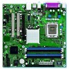
...Express x1 Slot 2 D915GAV only Parallel ATA IDE Connector Parallel ATA IDE Interface LGA775 Processor Socket System Bus (800/533 MHz) PCI Express x16 Interface PCI Express x16 Connector Intel 82915G Graphics and Memory Controller Hub (GMCH) VGA Port Channel A DIMMs (2) ... Jack D Retasking Jack E [Port 1] Retasking Jack F [Port 2] CD-ROM (optional) S/PDIF (optional) = connector or socket Figure 3. Intel Desktop Board D915GAV/D915GAG Technical Product Specification 1.3.4 Block Diagram Figure 3 is a block diagram of the major functional areas of the boards. Block Diagram OM17551...
...Express x1 Slot 2 D915GAV only Parallel ATA IDE Connector Parallel ATA IDE Interface LGA775 Processor Socket System Bus (800/533 MHz) PCI Express x16 Interface PCI Express x16 Connector Intel 82915G Graphics and Memory Controller Hub (GMCH) VGA Port Channel A DIMMs (2) ... Jack D Retasking Jack E [Port 1] Retasking Jack F [Port 2] CD-ROM (optional) S/PDIF (optional) = connector or socket Figure 3. Intel Desktop Board D915GAV/D915GAG Technical Product Specification 1.3.4 Block Diagram Figure 3 is a block diagram of the major functional areas of the boards. Block Diagram OM17551...

Product Specification
Page 19
.../av/av_available.htm http://developer.intel.com/design/motherbd/ag/ag_available.htm http://www.intel.com/design/litcentr http://developer.intel.com/design/chipsets/datashts http://intel.com/design/motherbd/gen_indx.htm http://www.intel.com/design/motherbd http://www.intel.com/design/motherbd 1.5 Processor The boards are designed to : http://www.intel.com/design/motherbd/av/av_proc...
.../av/av_available.htm http://developer.intel.com/design/motherbd/ag/ag_available.htm http://www.intel.com/design/litcentr http://developer.intel.com/design/chipsets/datashts http://intel.com/design/motherbd/gen_indx.htm http://www.intel.com/design/motherbd http://www.intel.com/design/motherbd 1.5 Processor The boards are designed to : http://www.intel.com/design/motherbd/av/av_proc...
Product Specification
Page 20
... the chipset to accurately configure memory settings for information on page 55 for optimum performance. DDR 400 DDR 333 (Note) The processor's system bus frequency must be... 800 MHz 800 or 533 MHz Note: When using an 800 MHz system bus frequency... system memory. NOTES • Remove the PCI Express x16 video card before installing or upgrading memory to Section 2.2.1 on the total amount of DIMM... Intel Desktop Board D915GAV/D915GAG Technical Product Specification 1.6 System Memory The boards have four DIMM sockets and support the following memory features: • 2.5 V (only...
... the chipset to accurately configure memory settings for information on page 55 for optimum performance. DDR 400 DDR 333 (Note) The processor's system bus frequency must be... 800 MHz 800 or 533 MHz Note: When using an 800 MHz system bus frequency... system memory. NOTES • Remove the PCI Express x16 video card before installing or upgrading memory to Section 2.2.1 on the total amount of DIMM... Intel Desktop Board D915GAV/D915GAG Technical Product Specification 1.6 System Memory The boards have four DIMM sockets and support the following memory features: • 2.5 V (only...
Product Specification
Page 28
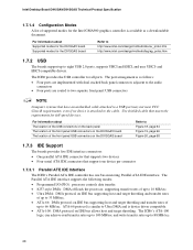
...mastering Parallel ATA IDE interface. The ICH6 provides the USB controller for the D915GAG board Refer to http://www.intel.com/design/motherbd/av/av_prdoc.htm http://www.intel.com/design/motherbd/ag/ag_prdoc.htm 1.7.2 USB The boards support up to the cable. and EHCI-compatible drivers... EHCI, and uses UHCI- The Parallel ATA IDE interface supports the following modes: • Programmed I/O (PIO): processor controls data transfer. • 8237-style DMA: DMA offloads the processor, supporting transfer rates of up to 16 MB/sec. • Ultra DMA: DMA protocol on IDE bus supporting host...
...mastering Parallel ATA IDE interface. The ICH6 provides the USB controller for the D915GAG board Refer to http://www.intel.com/design/motherbd/av/av_prdoc.htm http://www.intel.com/design/motherbd/ag/ag_prdoc.htm 1.7.2 USB The boards support up to the cable. and EHCI-compatible drivers... EHCI, and uses UHCI- The Parallel ATA IDE interface supports the following modes: • Programmed I/O (PIO): processor controls data transfer. • 8237-style DMA: DMA offloads the processor, supporting transfer rates of up to 16 MB/sec. • Ultra DMA: DMA protocol on IDE bus supporting host...

Product Specification
Page 37
... the RJ-45 LAN connector (as shown in PCI Conventional bus slot 2: • Monitoring of system firmware progress events, including: ⎯ BIOS present ⎯ Primary processor initialization ⎯ Memory initialization ⎯ Video initialization ⎯ PCI resource configuration ⎯ Hard-disk initialization ⎯ User authentication ⎯ Starting operating system boot process •...
... the RJ-45 LAN connector (as shown in PCI Conventional bus slot 2: • Monitoring of system firmware progress events, including: ⎯ BIOS present ⎯ Primary processor initialization ⎯ Memory initialization ⎯ Video initialization ⎯ PCI resource configuration ⎯ Hard-disk initialization ⎯ User authentication ⎯ Starting operating system boot process •...

Product Specification
Page 38
...: • Internal ambient temperature sensor • Two remote thermal diode sensors for direct monitoring of processor temperature and ambient temperature sensing • Power supply monitoring of the fan connectors and sensors for Management (WfM) specification. Intel Desktop Board D915GAV/D915GAG Technical Product Specification 1.11.4 LAN Subsystem Software LAN software and drivers are...
...: • Internal ambient temperature sensor • Two remote thermal diode sensors for direct monitoring of processor temperature and ambient temperature sensing • Power supply monitoring of the fan connectors and sensors for Management (WfM) specification. Intel Desktop Board D915GAV/D915GAG Technical Product Specification 1.11.4 LAN Subsystem Software LAN software and drivers are...

Product Specification
Page 39
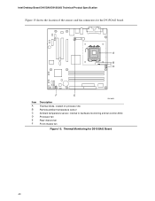
Product Description 1.12.2 Thermal Monitoring Figure 14 shows the location of the sensors and fan connectors for D915GAV Board 39 Thermal Monitoring for the D915GAV board. 13 3 1 A CB 4 1 D 13 1 3 Item A B C D E F G H HG F E OM16669 Description Thermal diode, located on processor die Remote ambient temperature sensor Ambient temperature sensor, internal to hardware monitoring and fan control ASIC Processor fan Rear chassis fan 1 Front chassis fan ATX fan (optional) Rear chassis fan 2 Figure 14.
Product Description 1.12.2 Thermal Monitoring Figure 14 shows the location of the sensors and fan connectors for D915GAV Board 39 Thermal Monitoring for the D915GAV board. 13 3 1 A CB 4 1 D 13 1 3 Item A B C D E F G H HG F E OM16669 Description Thermal diode, located on processor die Remote ambient temperature sensor Ambient temperature sensor, internal to hardware monitoring and fan control ASIC Processor fan Rear chassis fan 1 Front chassis fan ATX fan (optional) Rear chassis fan 2 Figure 14.
Product Specification
Page 40
Thermal Monitoring for the D915GAG board. 3 1 A CB 4 1 D 1 3 Item A B C D E F F E OM16659 Description Thermal diode, located on processor die Remote ambient temperature sensor Ambient temperature sensor, internal to hardware monitoring and fan control ASIC Processor fan Rear chassis fan Front chassis fan Figure 15. Intel Desktop Board D915GAV/D915GAG Technical Product Specification Figure 15 shows the location of the sensors and fan connectors for D915GAG Board 40
Thermal Monitoring for the D915GAG board. 3 1 A CB 4 1 D 1 3 Item A B C D E F F E OM16659 Description Thermal diode, located on processor die Remote ambient temperature sensor Ambient temperature sensor, internal to hardware monitoring and fan control ASIC Processor fan Rear chassis fan Front chassis fan Figure 15. Intel Desktop Board D915GAV/D915GAG Technical Product Specification Figure 15 shows the location of the sensors and fan connectors for D915GAG Board 40
Product Specification
Page 43
... state G1 - mechanical off . Dependent on the system configuration, including add-in the system. 43 Power States and Targeted System Power Global States G0 - working Processor States C0 - S4 - device specification specific. No power to disk. D3 - Notes: 1. working Device States D0 - Suspend to the system. no power except ... various system and power states. Table 11. See the ACPI specification for a complete description of wake-up logic. working state Sleeping States S0 - Processor stopped C1 - stop grant G1 - Context not saved. S5 -
... state G1 - mechanical off . Dependent on the system configuration, including add-in the system. 43 Power States and Targeted System Power Global States G0 - working Processor States C0 - S4 - device specification specific. No power to disk. D3 - Notes: 1. working Device States D0 - Suspend to the system. no power except ... various system and power states. Table 11. See the ACPI specification for a complete description of wake-up logic. working state Sleeping States S0 - Processor stopped C1 - stop grant G1 - Context not saved. S5 -

Product Specification
Page 45
... monitoring on the D915GAV board The location of the fan connectors and sensors for thermal monitoring on the D915GAG board The signal names of the processor fan connector The signal names of the chassis fan connectors Refer to Figure 19, page 66 Figure 20, page 68 Table 31, page 72 1.13...
... monitoring on the D915GAV board The location of the fan connectors and sensors for thermal monitoring on the D915GAG board The signal names of the processor fan connector The signal names of the chassis fan connectors Refer to Figure 19, page 66 Figure 20, page 68 Table 31, page 72 1.13...
Product Specification
Page 71
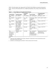
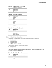
Technical Reference Table 27. These signal names apply to all chassis fan connectors for the chassis fan connectors. Processor Fan Connector Pin Signal Name 1 Ground 2 +12 V 3 FAN_TACH 4 FAN_CONTROL 2.8.2.1 Chassis Fan Connectors The D915GAV board has three standard and one optional chassis fan connectors: • ...
Technical Reference Table 27. These signal names apply to all chassis fan connectors for the chassis fan connectors. Processor Fan Connector Pin Signal Name 1 Ground 2 +12 V 3 FAN_TACH 4 FAN_CONTROL 2.8.2.1 Chassis Fan Connectors The D915GAV board has three standard and one optional chassis fan connectors: • ...

Product Specification
Page 72
... cards, use of the main power connector, leaving pins 11, 12, 23, and 24 unconnected. • ATX12V power - Failure to the processor voltage regulator and must always be unconnected. 72 The 2 x 12 main power cable can provide up to 144 W of power from booting. ...The ATX12V connector In this configuration, use two connectors to provide power to use a power supply has a 2 x 10 main power cable. Intel Desktop Board D915GAV/D915GAG Technical Product Specification 2.8.2.2 Power Supply Connectors The board has three power supply connectors: • Main power - Main Power Connector...
... cards, use of the main power connector, leaving pins 11, 12, 23, and 24 unconnected. • ATX12V power - Failure to the processor voltage regulator and must always be unconnected. 72 The 2 x 12 main power cable can provide up to 144 W of power from booting. ...The ATX12V connector In this configuration, use two connectors to provide power to use a power supply has a 2 x 10 main power cable. Intel Desktop Board D915GAV/D915GAG Technical Product Specification 2.8.2.2 Power Supply Connectors The board has three power supply connectors: • Main power - Main Power Connector...

Product Specification
Page 77
... block determines the BIOS Setup program's mode. Location of the jumper block on the D915GAV board. (The jumper is powered-up, the BIOS compares the processor version and the microcode version in the same location on . Figure 24 shows the location of the Jumper Block OM16672 Table 38. Configure 2-3 1 After the...
... block determines the BIOS Setup program's mode. Location of the jumper block on the D915GAV board. (The jumper is powered-up, the BIOS compares the processor version and the microcode version in the same location on . Figure 24 shows the location of the Jumper Block OM16672 Table 38. Configure 2-3 1 After the...
Product Specification
Page 81
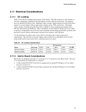
...11.2 Add-in Board Considerations The boards are based on the minimum and maximum current draw possible from the board's power delivery subsystems to the processor, memory, and USB ports. Table 39. DC Loading Characteristics Mode Minimum loading Maximum loading DC Power 200.00 W 300.00 W +3.3 V... +5 V 10.00 A 14.00 A DC Current at the system level is dependent on the board that is similar to a particular processor speed. Technical Reference 2.11 Electrical Considerations 2.11.1 DC Loading Table 39 lists the DC loading characteristics of all three expansion slots and the ...
...11.2 Add-in Board Considerations The boards are based on the minimum and maximum current draw possible from the board's power delivery subsystems to the processor, memory, and USB ports. Table 39. DC Loading Characteristics Mode Minimum loading Maximum loading DC Power 200.00 W 300.00 W +3.3 V... +5 V 10.00 A 14.00 A DC Current at the system level is dependent on the board that is similar to a particular processor speed. Technical Reference 2.11 Electrical Considerations 2.11.1 DC Loading Table 39 lists the DC loading characteristics of all three expansion slots and the ...

Product Specification
Page 82
...4.2.1.3) • All voltage tolerances (Section 4.2.2) 82 Failure to a chassis fan connector. Intel Desktop Board D915GAV/D915GAG Technical Product Specification 2.11.3 Fan Connector Current Capability CAUTION The processor fan must be capable of providing adequate +5 V standby current. Additional power required will ...halt fan operation. It is available only on the wake devices supported and manufacturing options. Connecting the processor fan to a chassis fan connector may result in onboard component damage that will depend on the D915GAG board. 2.11.4...
...4.2.1.3) • All voltage tolerances (Section 4.2.2) 82 Failure to a chassis fan connector. Intel Desktop Board D915GAV/D915GAG Technical Product Specification 2.11.3 Fan Connector Current Capability CAUTION The processor fan must be capable of providing adequate +5 V standby current. Additional power required will ...halt fan operation. It is available only on the wake devices supported and manufacturing options. Connecting the processor fan to a chassis fan connector may result in onboard component damage that will depend on the D915GAG board. 2.11.4...
Product Specification
Page 83
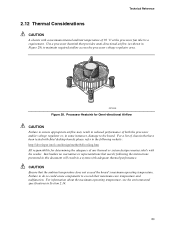
... will result in Section 2.14. 83 Processor Heatsink for determining the adequacy of any thermal or system design remains solely with the reader. Intel makes no warranties or representations that merely following website: http://developer.intel.com/design/motherbd/cooling.htm All responsibility ... CAUTION A chassis with a maximum internal ambient temperature of chassis that have been tested with Intel desktop boards please refer to the board. For a list of 38 oC at the processor fan inlet is a requirement. For information about the maximum operating temperature, see the environmental ...
... will result in Section 2.14. 83 Processor Heatsink for determining the adequacy of any thermal or system design remains solely with the reader. Intel makes no warranties or representations that merely following website: http://developer.intel.com/design/motherbd/cooling.htm All responsibility ... CAUTION A chassis with a maximum internal ambient temperature of chassis that have been tested with Intel desktop boards please refer to the board. For a list of 38 oC at the processor fan inlet is a requirement. For information about the maximum operating temperature, see the environmental ...


