
Product Specification
Page 5
Contents 1 Product Description 1.1 Overview 9 1.1.1 Feature Summary 9 1.1.2 Board Layout 11 1.1.3 Block Diagram 13 1.2 Legacy Considerations 14 1.3 Online Support 14 1.4 Processor 14 1.5 System Memory 15 1.5.1 Memory Configurations 16 1.6 Intel® G41 Express Chipset 18 1.6.1 Intel® G41 Graphics Subsystem 18 1.6.2 USB 20 1.6.3 Serial ATA Interfaces 21 1.7 Parallel IDE Controller 22 1.8 Real-Time Clock Subsystem 23 1.9 Legacy...
Contents 1 Product Description 1.1 Overview 9 1.1.1 Feature Summary 9 1.1.2 Board Layout 11 1.1.3 Block Diagram 13 1.2 Legacy Considerations 14 1.3 Online Support 14 1.4 Processor 14 1.5 System Memory 15 1.5.1 Memory Configurations 16 1.6 Intel® G41 Express Chipset 18 1.6.1 Intel® G41 Graphics Subsystem 18 1.6.2 USB 20 1.6.3 Serial ATA Interfaces 21 1.7 Parallel IDE Controller 22 1.8 Real-Time Clock Subsystem 23 1.9 Legacy...
Product Specification
Page 7
...Connector LED Locations 27 6. Back Panel Connectors 43 10. Location of Pressing the Power Switch 30 8. Audio Jack Retasking Support 24 6. Processor (4-pin) Fan Header 47 17. Detailed System Memory Address Map 40 9. Connection Diagram for AC '97 Audio 47 vii Localized High ... and Headers 44 11. HDMI Port Status Conditions 19 5. Front Panel Audio Header for Front Panel Header 50 12. Connection Diagram for Intel HD Audio 47 18. LAN Connector LED States 27 7. Component-side Connectors and Headers Shown in Figure 1 12 3. Location of Conformity...
...Connector LED Locations 27 6. Back Panel Connectors 43 10. Location of Pressing the Power Switch 30 8. Audio Jack Retasking Support 24 6. Processor (4-pin) Fan Header 47 17. Detailed System Memory Address Map 40 9. Connection Diagram for AC '97 Audio 47 vii Localized High ... and Headers 44 11. HDMI Port Status Conditions 19 5. Front Panel Audio Header for Front Panel Header 50 12. Connection Diagram for Intel HD Audio 47 18. LAN Connector LED States 27 7. Component-side Connectors and Headers Shown in Figure 1 12 3. Location of Conformity...

Product Specification
Page 8
... Menu Options 67 34. Front-panel Power LED Blink Codes 72 37. Safety Standards 79 42. Recommended Power Supply Current Values 56 27. Intel Desktop Board DG41KR Environmental Specifications 60 30. BIOS Setup Program Function Keys 62 32. BIOS Beep Codes 71 36. BIOS Error Messages 72 38.... Port 80h POST Code Ranges 73 39. Typical Port 80h POST Sequence 77 41. Processor Core Power Connector 49 20. States for a Two-Color Power LED 51 24. Fan Header Current Capability 57 28. Product Certification Markings 86 ...
... Menu Options 67 34. Front-panel Power LED Blink Codes 72 37. Safety Standards 79 42. Recommended Power Supply Current Values 56 27. Intel Desktop Board DG41KR Environmental Specifications 60 30. BIOS Setup Program Function Keys 62 32. BIOS Beep Codes 71 36. BIOS Error Messages 72 38.... Port 80h POST Code Ranges 73 39. Typical Port 80h POST Sequence 77 41. Processor Core Power Connector 49 20. States for a Two-Color Power LED 51 24. Fan Header Current Capability 57 28. Product Certification Markings 86 ...

Product Specification
Page 9
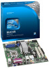
...for the following: • Intel® Core™2 Quad processor Q6000/Q8000/Q9000 series in an LGA775 socket • Intel® Core™2 Duo processor E4000/E6000/E7000/E8000 series in an LGA775 socket • Intel® Pentium® Dual-Core processor E2000/E5000 series in an LGA775... socket • Intel® Celeron® processor 400/1000 series in an LGA775 socket • Intel® Xeon® processor 3000/X3000 series in card connector 10-channel (7.1...
...for the following: • Intel® Core™2 Quad processor Q6000/Q8000/Q9000 series in an LGA775 socket • Intel® Core™2 Duo processor E4000/E6000/E7000/E8000 series in an LGA775 socket • Intel® Pentium® Dual-Core processor E2000/E5000 series in an LGA775... socket • Intel® Celeron® processor 400/1000 series in an LGA775 socket • Intel® Xeon® processor 3000/X3000 series in card connector 10-channel (7.1...
Product Specification
Page 14
... when falling within the wattage requirements of the board. The processors listed above . For information about ... This board is designed to ) the following processors: • Intel® Core™2 Quad processor Q6000/Q8000/Q9000 series in an LGA775 socket • Intel® Core™2 Duo processor E4000/E6000/E7000/E8000 series in an LGA775 socket •...
... when falling within the wattage requirements of the board. The processors listed above . For information about ... This board is designed to ) the following processors: • Intel® Core™2 Quad processor Q6000/Q8000/Q9000 series in an LGA775 socket • Intel® Core™2 Duo processor E4000/E6000/E7000/E8000 series in an LGA775 socket •...
Product Specification
Page 22
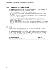
...rates of up to 66 MB/s. The BIOS supports Logical Block Addressing (LBA) and Extended Cylinder Head Sector (ECHS) translation modes. Intel Desktop Board DG41KR Technical Product Specification 1.7 Parallel IDE Controller The Parallel ATA IDE controller has one bus-mastering Parallel ATA IDE interface. ...10, page 44 22 The Parallel ATA IDE interface supports the following modes: • Programmed I/O (PIO): processor controls data transfer. • 8237-style DMA: DMA offloads the processor, supporting transfer rates of up to 16 MB/s. • Ultra DMA: DMA protocol on IDE bus supporting ...
...rates of up to 66 MB/s. The BIOS supports Logical Block Addressing (LBA) and Extended Cylinder Head Sector (ECHS) translation modes. Intel Desktop Board DG41KR Technical Product Specification 1.7 Parallel IDE Controller The Parallel ATA IDE controller has one bus-mastering Parallel ATA IDE interface. ...10, page 44 22 The Parallel ATA IDE interface supports the following modes: • Programmed I/O (PIO): processor controls data transfer. • 8237-style DMA: DMA offloads the processor, supporting transfer rates of up to 16 MB/s. • Ultra DMA: DMA protocol on IDE bus supporting ...
Product Specification
Page 28
... levels above or below acceptable values • Thermally monitored closed-loop fan control, for Management (WfM) specification. Intel Desktop Board DG41KR Technical Product Specification 1.12 Hardware Management Subsystem The hardware management features enable the board to be implemented... delivering acoustically-optimized thermal management • Fan speed control controllers and sensors integrated into the SIO • Three thermal sensors (processor, 82G41 GMCH, and 82801GB ICH7) • Power supply monitoring of monitoring and control is dependent on the I/O controller used...
... levels above or below acceptable values • Thermally monitored closed-loop fan control, for Management (WfM) specification. Intel Desktop Board DG41KR Technical Product Specification 1.12 Hardware Management Subsystem The hardware management features enable the board to be implemented... delivering acoustically-optimized thermal management • Fan speed control controllers and sensors integrated into the SIO • Three thermal sensors (processor, 82G41 GMCH, and 82801GB ICH7) • Power supply monitoring of monitoring and control is dependent on the I/O controller used...
Product Specification
Page 29
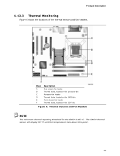
Thermal Sensors and Fan Headers NOTE The minimum thermal reporting threshold for the GMCH is 66 °C. The GMCH thermal sensor will display 66 °C until the temperature rises above this point. 29 Item A B C D E F Description Rear chassis fan header Thermal diode, located on the processor die Processor fan header Thermal diode, located on the GMCH die Front chassis fan header Thermal diode, located on the ICH7 die Figure 6. Product Description 1.12.3 Thermal Monitoring Figure 6 shows the locations of the thermal sensors and fan headers.
Thermal Sensors and Fan Headers NOTE The minimum thermal reporting threshold for the GMCH is 66 °C. The GMCH thermal sensor will display 66 °C until the temperature rises above this point. 29 Item A B C D E F Description Rear chassis fan header Thermal diode, located on the processor die Processor fan header Thermal diode, located on the GMCH die Front chassis fan header Thermal diode, located on the ICH7 die Figure 6. Product Description 1.12.3 Thermal Monitoring Figure 6 shows the locations of the thermal sensors and fan headers.
Product Specification
Page 31
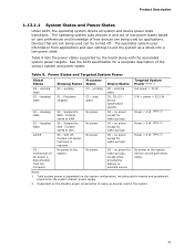
... user preferences and knowledge of how devices are not being used by battery or external source. Power States and Targeted System Power Global States G0 - Processor stopped C1 - S4 - No power to disk. D1, D2, D3 - D3 - Service can be performed safely. AC power is required. working S1 - Suspend to the...- Table 8. Product Description 1.13.1.1 System States and Power States Under ACPI, the operating system directs all system and device power state transitions. mechanical off . working Processor States C0 - Context saved to disk. Notes: 1. Context saved to RAM.
... user preferences and knowledge of how devices are not being used by battery or external source. Power States and Targeted System Power Global States G0 - Processor stopped C1 - S4 - No power to disk. D1, D2, D3 - D3 - Service can be performed safely. AC power is required. working S1 - Suspend to the...- Table 8. Product Description 1.13.1.1 System States and Power States Under ACPI, the operating system directs all system and device power state transitions. mechanical off . working Processor States C0 - Context saved to disk. Notes: 1. Context saved to RAM.
Product Specification
Page 34
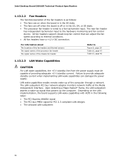
LAN wake capabilities enable remote wake-up the computer. Intel Desktop Board DG41KR Technical Product Specification 1.13.2.2 Fan Headers The function/operation of the computer through a network. Depending on when the board is in the ... must be capable of providing adequate +5 V standby current. For information about The locations of the fan headers and thermal sensors The signal names of the processor fan header The signal names of the chassis fan header Refer to the hardware monitoring and fan control device. The LAN subsystem PCI bus network...
LAN wake capabilities enable remote wake-up the computer. Intel Desktop Board DG41KR Technical Product Specification 1.13.2.2 Fan Headers The function/operation of the computer through a network. Depending on when the board is in the ... must be capable of providing adequate +5 V standby current. For information about The locations of the fan headers and thermal sensors The signal names of the processor fan header The signal names of the chassis fan header Refer to the hardware monitoring and fan control device. The LAN subsystem PCI bus network...
Product Specification
Page 45
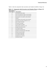
... bus add-in Figure 10. Table 11. Technical Reference Table 11 lists the component-side connectors and headers identified in card connector G Processor core power connector (2 x 2) H Rear chassis fan header I Processor fan header J Front chassis fan header K Main power connector (2 x 12) L Parallel ATA IDE connector M Front panel header N Serial ATA connectors (4) O Auxiliary...
... bus add-in Figure 10. Table 11. Technical Reference Table 11 lists the component-side connectors and headers identified in card connector G Processor core power connector (2 x 2) H Rear chassis fan header I Processor fan header J Front chassis fan header K Main power connector (2 x 12) L Parallel ATA IDE connector M Front panel header N Serial ATA connectors (4) O Auxiliary...
Product Specification
Page 47
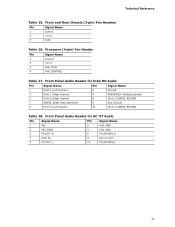
Technical Reference Table 15. Processor (4-pin) Fan Header Pin Signal Name 1 Ground 2 +12 V 3 FAN_TACH 4 FAN_CONTROL Table 17. Front Panel Audio Header for Intel HD Audio Pin Signal Name Pin Signal Name 1 [Port 1] Left channel 3 [Port 1] Right channel 5 [Port 2] Right channel 7 SENSE_SEND (Jack detection) 9 [Port 2] Left channel 2 Ground 4 PRESENCE# (...
Technical Reference Table 15. Processor (4-pin) Fan Header Pin Signal Name 1 Ground 2 +12 V 3 FAN_TACH 4 FAN_CONTROL Table 17. Front Panel Audio Header for Intel HD Audio Pin Signal Name Pin Signal Name 1 [Port 1] Left channel 3 [Port 1] Right channel 5 [Port 2] Right channel 7 SENSE_SEND (Jack detection) 9 [Port 2] Left channel 2 Ground 4 PRESENCE# (...
Product Specification
Page 49
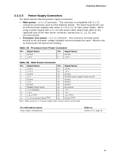
...so will be used on the rightmost pins of ATX12V power supplies with either 2 x 10 or 2 x 12 main power cables. a 2 x 2 connector. Processor Core Power Connector Pin Signal Name 1 Ground 3 +12 V Pin Signal Name 2 Ground 4 +12 V Table 20. Main Power Connector Pin Signal Name Pin ... of the main power connector, leaving pins 11, 12, 23, and 24 unconnected. • Processor core power - This connector is compatible with a 2 x 10 main power cable, attach that cable on Intel Desktop boards. This connector provides power directly to Section 2.5.1, page 56 49 a 2 x 12 ...
...so will be used on the rightmost pins of ATX12V power supplies with either 2 x 10 or 2 x 12 main power cables. a 2 x 2 connector. Processor Core Power Connector Pin Signal Name 1 Ground 3 +12 V Pin Signal Name 2 Ground 4 +12 V Table 20. Main Power Connector Pin Signal Name Pin ... of the main power connector, leaving pins 11, 12, 23, and 24 unconnected. • Processor core power - This connector is compatible with a 2 x 10 main power cable, attach that cable on Intel Desktop boards. This connector provides power directly to Section 2.5.1, page 56 49 a 2 x 12 ...
Product Specification
Page 53
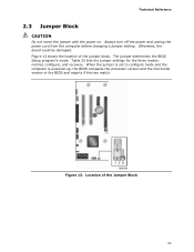
When the jumper is set to configure mode and the computer is powered-up, the BIOS compares the processor version and the microcode version in the BIOS and reports if the two match. The jumper determines the BIOS Setup program's mode. Otherwise, the board ...
When the jumper is set to configure mode and the computer is powered-up, the BIOS compares the processor version and the microcode version in the BIOS and reports if the two match. The jumper determines the BIOS Setup program's mode. Otherwise, the board ...
Product Specification
Page 56
...standby current. Table 26. Additional power required will depend on page 14 for a system consisting of a supported 65 W processor (see Section 1.4 on configurations chosen by the integrator. Table 26 lists the recommended power supply current values. Failure to...A 0.3 A 5 VSB 3.0 A 56 The total amount of standby current required depends on the wake devices supported and manufacturing options. Intel Desktop Board DG41KR Technical Product Specification 2.5 Electrical Considerations 2.5.1 Power Supply Considerations CAUTION The +5 V standby line from the power supply must comply...
...standby current. Table 26. Additional power required will depend on page 14 for a system consisting of a supported 65 W processor (see Section 1.4 on configurations chosen by the integrator. Table 26 lists the recommended power supply current values. Failure to...A 0.3 A 5 VSB 3.0 A 56 The total amount of standby current required depends on the wake devices supported and manufacturing options. Intel Desktop Board DG41KR Technical Product Specification 2.5 Electrical Considerations 2.5.1 Power Supply Considerations CAUTION The +5 V standby line from the power supply must comply...
Product Specification
Page 57
... result in onboard component damage that merely following website: http://www3.intel.com/cd/channel/reseller/asmo-na/eng/tech_reference/53211.htm All responsibility for determining the adequacy of both the processor and/or voltage regulator or, in reduced performance of any thermal... or system design remains solely with adequate thermal performance. Connecting the processor fan to a chassis fan header may result in some instances, damage to exceed their maximum case temperature and malfunction. Intel makes no warranties or representations that will result in Section 2.8. 57...
... result in onboard component damage that merely following website: http://www3.intel.com/cd/channel/reseller/asmo-na/eng/tech_reference/53211.htm All responsibility for determining the adequacy of both the processor and/or voltage regulator or, in reduced performance of any thermal... or system design remains solely with adequate thermal performance. Connecting the processor fan to a chassis fan header may result in some instances, damage to exceed their maximum case temperature and malfunction. Intel makes no warranties or representations that will result in Section 2.8. 57...
Product Specification
Page 58
Item A B C D Description Processor voltage regulator area Processor Intel 82G41 GMCH Intel 82801GB (ICH7) Figure 15. Figure 15 shows the locations of up to 95 oC in Figure 15) can reach a temperature of the localized high temperature zones. Localized High Temperature Zones 58 Failure to do so may result in the processor voltage regulator circuit. Intel Desktop Board DG41KR Technical Product Specification CAUTION Ensure that proper airflow is maintained in damage to the voltage regulator circuit. The processor voltage regulator area (shown in an open chassis.
Item A B C D Description Processor voltage regulator area Processor Intel 82G41 GMCH Intel 82801GB (ICH7) Figure 15. Figure 15 shows the locations of up to 95 oC in Figure 15) can reach a temperature of the localized high temperature zones. Localized High Temperature Zones 58 Failure to do so may result in the processor voltage regulator circuit. Intel Desktop Board DG41KR Technical Product Specification CAUTION Ensure that proper airflow is maintained in damage to the voltage regulator circuit. The processor voltage regulator area (shown in an open chassis.
Product Specification
Page 59
... ºC. Technical Reference Table 28 provides maximum case temperatures for Components Component Processor Intel 82G41 GMCH Intel 82801GB (ICH7) Maximum Case Temperature For processor case temperature, see processor datasheets and processor specification updates 102 oC (under bias) 108 oC (under bias) For information about Processor datasheets and specification updates Refer to Section 1.2, page 14 2.7 Reliability The Mean...
... ºC. Technical Reference Table 28 provides maximum case temperatures for Components Component Processor Intel 82G41 GMCH Intel 82801GB (ICH7) Maximum Case Temperature For processor case temperature, see processor datasheets and processor specification updates 102 oC (under bias) 108 oC (under bias) For information about Processor datasheets and specification updates Refer to Section 1.2, page 14 2.7 Reliability The Mean...

Product Specification
Page 62
BIOS Setup Program Menu Bar Maintenance Main Advanced Security Clears passwords and displays processor information Displays processor and memory configuration Configures advanced features available through the chipset Sets passwords and security features Power Boot Configures power management features and... (SPI Flash) includes an 8 Mbit (1024 KB) flash memory device. 3.3 Resource Configuration 3.3.1 PCI Autoconfiguration The BIOS can automatically configure PCI devices. Intel Desktop Board DG41KR Technical Product Specification Table 30 lists the BIOS Setup program menu features.
BIOS Setup Program Menu Bar Maintenance Main Advanced Security Clears passwords and displays processor information Displays processor and memory configuration Configures advanced features available through the chipset Sets passwords and security features Power Boot Configures power management features and... (SPI Flash) includes an 8 Mbit (1024 KB) flash memory device. 3.3 Resource Configuration 3.3.1 PCI Autoconfiguration The BIOS can automatically configure PCI devices. Intel Desktop Board DG41KR Technical Product Specification Table 30 lists the BIOS Setup program menu features.
Product Specification
Page 63
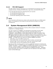
... BIOS revision level • Fixed-system data, such as peripherals, serial numbers, and asset tags • Resource data, such as memory size, cache size, and processor speed • Dynamic data, such as event detection and error logging Non-Plug and Play operating systems require an additional interface for system components. Additional...
... BIOS revision level • Fixed-system data, such as peripherals, serial numbers, and asset tags • Resource data, such as memory size, cache size, and processor speed • Dynamic data, such as event detection and error logging Non-Plug and Play operating systems require an additional interface for system components. Additional...


