
Product Specification
Page 5
Contents 1 Product Description9 1.1 Overview 9 1.1.1 Feature Summary 9 1.1.2 Board Layout 11 1.1.3 Block Diagram 13 1.2 Legacy Considerations 14 1.3 Online Support 14 1.4 Processor 14 1.5 System Memory 15 1.5.1 Memory Configurations 16 1.6 Intel® G41 Express Chipset 18 1.6.1 Intel G41 Graphics Subsystem 18 1.6.2 USB 20 1.6.3 Serial ATA Interfaces 20 1.7 Real-Time Clock Subsystem 21 1.8 Legacy I/O Controller 21 1.8.1 Serial Port Interface...
Contents 1 Product Description9 1.1 Overview 9 1.1.1 Feature Summary 9 1.1.2 Board Layout 11 1.1.3 Block Diagram 13 1.2 Legacy Considerations 14 1.3 Online Support 14 1.4 Processor 14 1.5 System Memory 15 1.5.1 Memory Configurations 16 1.6 Intel® G41 Express Chipset 18 1.6.1 Intel G41 Graphics Subsystem 18 1.6.2 USB 20 1.6.3 Serial ATA Interfaces 20 1.7 Real-Time Clock Subsystem 21 1.8 Legacy I/O Controller 21 1.8.1 Serial Port Interface...

Product Specification
Page 7
Connection Diagram for Intel® HD Audio 43 17. LAN Connector LED States 25 6. Component-side Connectors and Headers Shown in Figure 1 12 3. Processor Fan Header 42 16. Front Panel Audio Header for Front Panel USB Headers 47 13. BIOS Setup Configuration Jumper Settings 49... Connectors 42 12. States for a One-Color Power LED 46 23. Recommended Power Supply Current Values 51 27. Audio Jack Support 22 5. Processor Core Power Connector 44 20. Detailed System Memory Address Map 36 9. Effects of Pressing the Power Switch 28 7. Serial Port Header 42 14...
Connection Diagram for Intel® HD Audio 43 17. LAN Connector LED States 25 6. Component-side Connectors and Headers Shown in Figure 1 12 3. Processor Fan Header 42 16. Front Panel Audio Header for Front Panel USB Headers 47 13. BIOS Setup Configuration Jumper Settings 49... Connectors 42 12. States for a One-Color Power LED 46 23. Recommended Power Supply Current Values 51 27. Audio Jack Support 22 5. Processor Core Power Connector 44 20. Detailed System Memory Address Map 36 9. Effects of Pressing the Power Switch 28 7. Serial Port Header 42 14...
Product Specification
Page 9
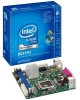
... Video Support for the following: • Intel® Celeron® processor 400 Sequence in an LGA775 socket • Intel® Xeon® processor 3000 Sequence in an LGA775 socket • Intel® Core™2 Duo processor in an LGA775 socket • Intel® Pentium® Dual-Core processor in an LGA775 socket • Intel® Celeron® Dual-Core...
... Video Support for the following: • Intel® Celeron® processor 400 Sequence in an LGA775 socket • Intel® Xeon® processor 3000 Sequence in an LGA775 socket • Intel® Core™2 Duo processor in an LGA775 socket • Intel® Pentium® Dual-Core processor in an LGA775 socket • Intel® Celeron® Dual-Core...

Product Specification
Page 14
... only supported when falling within the wattage requirements of the board. Use of supported processors. Intel Desktop Board DG41MJ Technical Product Specification 1.2 Legacy Considerations This board differs from other Intel® Desktop Board products, with a maximum wattage of 65 W. Intel Desktop Board DG41MJ Desktop Board Support Available configurations for the most up-to ) the...
... only supported when falling within the wattage requirements of the board. Use of supported processors. Intel Desktop Board DG41MJ Technical Product Specification 1.2 Legacy Considerations This board differs from other Intel® Desktop Board products, with a maximum wattage of 65 W. Intel Desktop Board DG41MJ Desktop Board Support Available configurations for the most up-to ) the...

Product Specification
Page 18
... board's I /O Controller Hub (ICH7) with Direct Media Interface (DMI) interconnect • Intel 82801GB I /O paths. The ICH7 is disabled. 1.6.1.1 Intel® Graphics Media Accelerator X4500 Graphics Controller The Intel GMA X4500 graphics controller features the following: • High quality texture engine ⎯ DirectX10*...9135; 16-bit and 32-bit color ⎯ Vertex cache • Video ⎯ High Definition content at up to the processor, memory, PCI, and the DMI interconnect. The chipset supports the following features: • Onboard graphics • Dynamic Video Memory ...
... board's I /O Controller Hub (ICH7) with Direct Media Interface (DMI) interconnect • Intel 82801GB I /O paths. The ICH7 is disabled. 1.6.1.1 Intel® Graphics Media Accelerator X4500 Graphics Controller The Intel GMA X4500 graphics controller features the following: • High quality texture engine ⎯ DirectX10*...9135; 16-bit and 32-bit color ⎯ Vertex cache • Video ⎯ High Definition content at up to the processor, memory, PCI, and the DMI interconnect. The chipset supports the following features: • Onboard graphics • Dynamic Video Memory ...
Product Specification
Page 26
...is removed, the mechanical switch is removed. The security feature uses a mechanical switch on the I /O Controller • Four thermal sensors (processor, 82G41 GMCH, 82801GB ICH7, and a remote thermal sensor) • Power supply monitoring of the chassis intrusion header Refer to the chassis ...the chassis that detects if the chassis cover is in the closed -loop fan control, for Management (WfM) specification. Intel Desktop Board DG41MJ Technical Product Specification 1.11 Hardware Management Subsystem The hardware management features enable the board to be implemented using ...
...is removed, the mechanical switch is removed. The security feature uses a mechanical switch on the I /O Controller • Four thermal sensors (processor, 82G41 GMCH, 82801GB ICH7, and a remote thermal sensor) • Power supply monitoring of the chassis intrusion header Refer to the chassis ...the chassis that detects if the chassis cover is in the closed -loop fan control, for Management (WfM) specification. Intel Desktop Board DG41MJ Technical Product Specification 1.11 Hardware Management Subsystem The hardware management features enable the board to be implemented using ...

Product Specification
Page 27
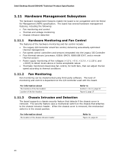
The GMCH thermal sensor will display 66 °C until the temperature rises above this point. 27 Thermal Sensors and Fan Headers NOTE The minimum thermal reporting threshold for the GMCH is 66 °C. Item A B C D E Description Thermal diode, located on the processor die Front chassis fan Processor fan Thermal diode, located on the GMCH die Thermal diode, located on the ICH7 die Figure 6. Product Description 1.11.4 Thermal Monitoring Figure 6 shows the locations of the thermal sensors and fan headers.
The GMCH thermal sensor will display 66 °C until the temperature rises above this point. 27 Thermal Sensors and Fan Headers NOTE The minimum thermal reporting threshold for the GMCH is 66 °C. Item A B C D E Description Thermal diode, located on the processor die Front chassis fan Processor fan Thermal diode, located on the GMCH die Thermal diode, located on the ICH7 die Figure 6. Product Description 1.11.4 Thermal Monitoring Figure 6 shows the locations of the thermal sensors and fan headers.
Product Specification
Page 29
...5 W (Note 2) Power < 5 W (Note 2) Power < 5 W (Note 2) D3 - Context saved to the system. Power States and Targeted System Power Global States Processor Sleeping States States Device States Targeted System Power (Note 1) G0 - Dependent on user preferences and knowledge of the various system and power states. The operating... G1 - Cold boot is required. D3 - no power except for wake-up devices used can be turned off. Processor stopped C1 - Product Description 1.12.1.1 System States and Power States Under ACPI, the operating system directs all system and...
...5 W (Note 2) Power < 5 W (Note 2) Power < 5 W (Note 2) D3 - Context saved to the system. Power States and Targeted System Power Global States Processor Sleeping States States Device States Targeted System Power (Note 1) G0 - Dependent on user preferences and knowledge of the various system and power states. The operating... G1 - Cold boot is required. D3 - no power except for wake-up devices used can be turned off. Processor stopped C1 - Product Description 1.12.1.1 System States and Power States Under ACPI, the operating system directs all system and...
Product Specification
Page 32
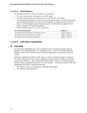
...header The signal names of the chassis fan header Refer to the hardware monitoring and fan control device. Failure to a fan tachometer input. Intel Desktop Board DG41MJ Technical Product Specification 1.12.2.2 Fan Headers The function/operation of the fan headers is as follows: • The fans... of the computer through a network. The board supports LAN wake capabilities with ACPI in the S3, S4, or S5 state. • The processor fan header is off when the board is wired to provide adequate standby current when implementing LAN wake capabilities can adjust the fan speed according...
...header The signal names of the chassis fan header Refer to the hardware monitoring and fan control device. Failure to a fan tachometer input. Intel Desktop Board DG41MJ Technical Product Specification 1.12.2.2 Fan Headers The function/operation of the fan headers is as follows: • The fans... of the computer through a network. The board supports LAN wake capabilities with ACPI in the S3, S4, or S5 state. • The processor fan header is off when the board is wired to provide adequate standby current when implementing LAN wake capabilities can adjust the fan speed according...

Product Specification
Page 41
... power connector (2 X 2) C Front panel USB header D Front panel USB header E Auxiliary front panel power LED header F Front chassis fan header G Processor fan header H Serial port header I Main power connector (2 X 12) J Front panel header K Serial ATA connectors (3) L PCI Conventional bus add-in Figure 10. Technical Reference Table ...
... power connector (2 X 2) C Front panel USB header D Front panel USB header E Auxiliary front panel power LED header F Front chassis fan header G Processor fan header H Serial port header I Main power connector (2 X 12) J Front panel header K Serial ATA connectors (3) L PCI Conventional bus add-in Figure 10. Technical Reference Table ...
Product Specification
Page 42
Processor Fan Header Pin Signal Name 1 Ground 2 +12 V 3 FAN_TACH 4 FAN_CONTROL 42 Serial Port Header Pin Signal Name 1 DCD 3 TXD# 5 Ground 7 RTS 9 RI Pin Signal Name 2 RXD# 4 DTR 6 DSR 8 CTS 10 Key (no pin) Table 14. Front Chassis Fan Header Pin Signal Name 1 Control 2 +12 V 3 Tach Table 15. Intel Desktop Board DG41MJ Technical Product...
Processor Fan Header Pin Signal Name 1 Ground 2 +12 V 3 FAN_TACH 4 FAN_CONTROL 42 Serial Port Header Pin Signal Name 1 DCD 3 TXD# 5 Ground 7 RTS 9 RI Pin Signal Name 2 RXD# 4 DTR 6 DSR 8 CTS 10 Key (no pin) Table 14. Front Chassis Fan Header Pin Signal Name 1 Control 2 +12 V 3 Tach Table 15. Intel Desktop Board DG41MJ Technical Product...
Product Specification
Page 44
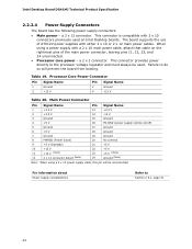
... 1 +3.3 V 13 +3.3 V 2 +3.3 V 14 -12 V 3 Ground 15 Ground 4 +5 V 16 PS-ON# (power supply remote on Intel Desktop boards. Processor Core Power Connector Pin Signal Name Pin Signal Name 1 Ground 3 +12 V 2 Ground 4 +12 V Table 20. Failure to Section 2.5.1, page ... V 23 +5 V (Note) 24 Ground (Note) Note: When using a power supply with either 2 x 10 or 2 x 12 main power cables. Intel Desktop Board DG41MJ Technical Product Specification 2.2.2.4 Power Supply Connectors The board has the following power supply connectors: • Main power - Table 19. a 2 x ...
... 1 +3.3 V 13 +3.3 V 2 +3.3 V 14 -12 V 3 Ground 15 Ground 4 +5 V 16 PS-ON# (power supply remote on Intel Desktop boards. Processor Core Power Connector Pin Signal Name Pin Signal Name 1 Ground 3 +12 V 2 Ground 4 +12 V Table 20. Failure to Section 2.5.1, page ... V 23 +5 V (Note) 24 Ground (Note) Note: When using a power supply with either 2 x 10 or 2 x 12 main power cables. Intel Desktop Board DG41MJ Technical Product Specification 2.2.2.4 Power Supply Connectors The board has the following power supply connectors: • Main power - Table 19. a 2 x ...

Product Specification
Page 48
The jumper determines the BIOS Setup program's mode. Figure 13. Intel Desktop Board DG41MJ Technical Product Specification 2.3 Jumper Block CAUTION Do not move the jumper with the power on. Table 25 lists the jumper settings for ... the location of the Jumper Block 48 When the jumper is set to configure mode and the computer is powered-up, the BIOS compares the processor version and the microcode version in the BIOS and reports if the two match. Always turn off the power and unplug the power cord from...
The jumper determines the BIOS Setup program's mode. Figure 13. Intel Desktop Board DG41MJ Technical Product Specification 2.3 Jumper Block CAUTION Do not move the jumper with the power on. Table 25 lists the jumper settings for ... the location of the Jumper Block 48 When the jumper is set to configure mode and the computer is powered-up, the BIOS compares the processor version and the microcode version in the BIOS and reports if the two match. Always turn off the power and unplug the power cord from...

Product Specification
Page 51
... of the +5 VSB line • All timing parameters • All voltage tolerances For example, for a system consisting of a supported 65 W processor (see Section 1.4 on page 14 for a list of supported processors), 1 GB DDR2 RAM, one hard disk drive, one optical drive, and all board peripherals enabled, the minimum recommended power supply is...
... of the +5 VSB line • All timing parameters • All voltage tolerances For example, for a system consisting of a supported 65 W processor (see Section 1.4 on page 14 for a list of supported processors), 1 GB DDR2 RAM, one hard disk drive, one optical drive, and all board peripherals enabled, the minimum recommended power supply is...
Product Specification
Page 52
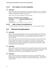
... in damage to do so may result in Section 2.8. Connecting the processor fan to the board. Failure to the voltage regulator circuit. Intel Desktop Board DG41MJ Technical Product Specification 2.5.2 Fan Header Current Capability CAUTION The processor fan must be connected to the processor fan header, not to exceed their maximum case temperature and malfunction...
... in damage to do so may result in Section 2.8. Connecting the processor fan to the board. Failure to the voltage regulator circuit. Intel Desktop Board DG41MJ Technical Product Specification 2.5.2 Fan Header Current Capability CAUTION The processor fan must be connected to the processor fan header, not to exceed their maximum case temperature and malfunction...
Product Specification
Page 53
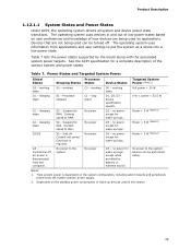
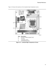
Item A B C D Description Processor voltage regulator area Processor Intel 82G41 GMCH Intel 82801GB (ICH7) Figure 15. Technical Reference Figure 15 shows the locations of the localized high temperature zones. Localized High Temperature Zones 53
Item A B C D Description Processor voltage regulator area Processor Intel 82G41 GMCH Intel 82801GB (ICH7) Figure 15. Technical Reference Figure 15 shows the locations of the localized high temperature zones. Localized High Temperature Zones 53

Product Specification
Page 54
... Product Specification Table 28 provides maximum case temperatures for Components Component Maximum Case Temperature Processor For processor case temperature, see processor datasheets and processor specification updates Intel 82G41 GMCH Intel 82801GB (ICH7) 102 oC (under bias) 108 oC (under bias) For information about Processor datasheets and specification updates Refer to Section 1.2, page 14 2.7 Reliability The Mean Time...
... Product Specification Table 28 provides maximum case temperatures for Components Component Maximum Case Temperature Processor For processor case temperature, see processor datasheets and processor specification updates Intel 82G41 GMCH Intel 82801GB (ICH7) 102 oC (under bias) 108 oC (under bias) For information about Processor datasheets and specification updates Refer to Section 1.2, page 14 2.7 Reliability The Mean Time...
Product Specification
Page 57
The initial production BIOSs are identified as MJG4110H.86A. The menu bar is powered-up, the BIOS compares the processor version and the microcode version in the BIOS and reports if the two match. When the BIOS Setup configuration jumper is set to configure ... computer. 3 Overview of BIOS and a revision code. The BIOS displays a message during POST identifying the type of BIOS Features 3.1 Introduction The board uses an Intel BIOS that is stored in the Serial Peripheral Interface Flash Memory (SPI Flash) and can be updated using a disk-based program. The SPI Flash contains...
The initial production BIOSs are identified as MJG4110H.86A. The menu bar is powered-up, the BIOS compares the processor version and the microcode version in the BIOS and reports if the two match. When the BIOS Setup configuration jumper is set to configure ... computer. 3 Overview of BIOS and a revision code. The BIOS displays a message during POST identifying the type of BIOS Features 3.1 Introduction The board uses an Intel BIOS that is stored in the Serial Peripheral Interface Flash Memory (SPI Flash) and can be updated using a disk-based program. The SPI Flash contains...

Product Specification
Page 58
BIOS Setup Program Menu Bar Maintenance Main Advanced Security Clears passwords and displays processor information Displays processor and memory configuration Configures advanced features available through the chipset Sets passwords and security features Power Boot Configures ...field (Not implemented) Executes command or selects the submenu Load the default configuration values for use by the add-in cards. Table 30. Intel Desktop Board DG41MJ Technical Product Specification Table 30 lists the BIOS Setup program menu features. When a user turns on the system after adding ...
BIOS Setup Program Menu Bar Maintenance Main Advanced Security Clears passwords and displays processor information Displays processor and memory configuration Configures advanced features available through the chipset Sets passwords and security features Power Boot Configures ...field (Not implemented) Executes command or selects the submenu Load the default configuration values for use by the add-in cards. Table 30. Intel Desktop Board DG41MJ Technical Product Specification Table 30 lists the BIOS Setup program menu features. When a user turns on the system after adding ...

Product Specification
Page 59
...Fixed-system data, such as peripherals, serial numbers, and asset tags • Resource data, such as memory size, cache size, and processor speed • Dynamic data, such as event detection and error logging Non-Plug and Play operating systems require an additional interface for such operating...to configure the operating system. (Keyboards and mice are not yet available. POST completes. 5. While the operating system is enabled by using Intel® Integrator Toolkit. 59 By default, Legacy USB support is disabled. 2. When you to Disabled in the BIOS under the Additional Information...
...Fixed-system data, such as peripherals, serial numbers, and asset tags • Resource data, such as memory size, cache size, and processor speed • Dynamic data, such as event detection and error logging Non-Plug and Play operating systems require an additional interface for such operating...to configure the operating system. (Keyboards and mice are not yet available. POST completes. 5. While the operating system is enabled by using Intel® Integrator Toolkit. 59 By default, Legacy USB support is disabled. 2. When you to Disabled in the BIOS under the Additional Information...


