
Product Guide
Page 3
... 2 Installing and Replacing Desktop Board Components: instructions on how to update the BIOS A Error Messages and Indicators: information about BIOS error messages and beep codes B Regulatory Compliance: describes the board's adherence to safety standards and EMC regulations and its product certifications Conventions The following conventions are evaluated as medical, industrial, alarm systems, test equipment, etc. iii may not be supported without further evaluation by Intel...
... 2 Installing and Replacing Desktop Board Components: instructions on how to update the BIOS A Error Messages and Indicators: information about BIOS error messages and beep codes B Regulatory Compliance: describes the board's adherence to safety standards and EMC regulations and its product certifications Conventions The following conventions are evaluated as medical, industrial, alarm systems, test equipment, etc. iii may not be supported without further evaluation by Intel...

Product Guide
Page 5
... Chipset 14 Main Memory...15 Graphics Subsystem 15 Integrated Graphics 15 Analog Display (VGA 15 High-Definition Multimedia Interface* (HDMI 16 Digital Visual Interface (DVI-D 16 PCI Express* x16 Graphics 16 Audio Subsystem 17 LAN Subsystem 17 USB 2.0 Support 18 Serial ATA Support 18 Expandability...19 Legacy I/O ...19 BIOS ...19 Serial ATA Auto Configuration 19 PCI*/PCI Express Auto Configuration 19 Security Passwords 20 Hardware Management 20 Hardware Monitoring and Fan Speed Control 20 Fan Monitoring 20 Chassis Intrusion 21 Power Management 21 Software Support 21 ACPI...
... Chipset 14 Main Memory...15 Graphics Subsystem 15 Integrated Graphics 15 Analog Display (VGA 15 High-Definition Multimedia Interface* (HDMI 16 Digital Visual Interface (DVI-D 16 PCI Express* x16 Graphics 16 Audio Subsystem 17 LAN Subsystem 17 USB 2.0 Support 18 Serial ATA Support 18 Expandability...19 Legacy I/O ...19 BIOS ...19 Serial ATA Auto Configuration 19 PCI*/PCI Express Auto Configuration 19 Security Passwords 20 Hardware Management 20 Hardware Monitoring and Fan Speed Control 20 Fan Monitoring 20 Chassis Intrusion 21 Power Management 21 Software Support 21 ACPI...

Product Guide
Page 6
...a PCI Express x16 Graphics Card 41 Removing a PCI Express x16 Graphics Card 42 Connecting Serial ATA (SATA) Cables 44 Installing an Intel® Z-U130 USB Solid-State Drive (or Compatible Device 45 Connecting to the Internal Headers 46 Front Panel Audio Header 47 Internal Mono Speaker Header 47 S/PDIF Header 48 Parallel Port Header 48 Chassis Intrusion Header 49 Intel® RPAT Header 49 Alternate Front Panel Power LED Header 49 Front Panel Header 50 Front Panel USB 2.0 Headers 50 Serial Header 51 Connecting to the Audio System 52 Connecting Chassis Fan and Power Supply Cables...
...a PCI Express x16 Graphics Card 41 Removing a PCI Express x16 Graphics Card 42 Connecting Serial ATA (SATA) Cables 44 Installing an Intel® Z-U130 USB Solid-State Drive (or Compatible Device 45 Connecting to the Internal Headers 46 Front Panel Audio Header 47 Internal Mono Speaker Header 47 S/PDIF Header 48 Parallel Port Header 48 Chassis Intrusion Header 49 Intel® RPAT Header 49 Alternate Front Panel Power LED Header 49 Front Panel Header 50 Front Panel USB 2.0 Headers 50 Serial Header 51 Connecting to the Audio System 52 Connecting Chassis Fan and Power Supply Cables...

Product Guide
Page 7
... Intel Z-U130 USB Solid-State Drive (or Compatible Device 45 23. Installing a PCI Express x16 Graphics Card 42 20. Contents A Error Messages and Indicators BIOS Error Codes 67 BIOS Error Messages 68 B Regulatory Compliance Safety Standards 69 Place Battery Marking 69 European Union Declaration of Conformity Statement 70 Product Ecology Statements 71 Recycling Considerations 71 Lead-free 2LI/Pb-free 2LI Board 74 Restriction of the BIOS Configuration Jumper Block 55 28. LAN Connector LEDs 18 3. Connecting Power Supply Cables...
... Intel Z-U130 USB Solid-State Drive (or Compatible Device 45 23. Installing a PCI Express x16 Graphics Card 42 20. Contents A Error Messages and Indicators BIOS Error Codes 67 BIOS Error Messages 68 B Regulatory Compliance Safety Standards 69 Place Battery Marking 69 European Union Declaration of Conformity Statement 70 Product Ecology Statements 71 Recycling Considerations 71 Lead-free 2LI/Pb-free 2LI Board 74 Restriction of the BIOS Configuration Jumper Block 55 28. LAN Connector LEDs 18 3. Connecting Power Supply Cables...

Product Guide
Page 8
... the BIOS Setup Program Modes 56 17. Internal Mono Speaker Header 47 7. Parallel Port Header 48 9. Intel RPAT Header Signal Names 49 11. Front Panel Header Signal Names 50 13. Jumper Settings for Intel HD Audio 47 5. Lead-Free Second Level Interconnect Marks 75 22. LAN Connector LEDs 18 4. Alternate Front Panel Power LED Header Signal Names 49 12. Front Panel USB Header (with Intel Z-U130 USB Solid-State Drive (or Compatible Device) Support) Signal Names 51 15. Serial Port Header 51 16. Front-panel Power LED Blink Codes 68...
... the BIOS Setup Program Modes 56 17. Internal Mono Speaker Header 47 7. Parallel Port Header 48 9. Intel RPAT Header Signal Names 49 11. Front Panel Header Signal Names 50 13. Jumper Settings for Intel HD Audio 47 5. Lead-Free Second Level Interconnect Marks 75 22. LAN Connector LEDs 18 4. Alternate Front Panel Power LED Header Signal Names 49 12. Front Panel USB Header (with Intel Z-U130 USB Solid-State Drive (or Compatible Device) Support) Signal Names 51 15. Serial Port Header 51 16. Front-panel Power LED Blink Codes 68...

Product Guide
Page 10
... back panel connector with three dual-port internal headers; Feature Summary (continued) Peripheral Interfaces LAN Support BIOS • Twelve USB 2.0 ports: ― Six ports are implemented with stacked back panel connectors ― Six ports are implemented with integrated status LEDs • Intel® BIOS resident in an SPI Flash device • Support for Advanced Configuration and Power Interface (ACPI), Plug and Play, and SMBIOS Instantly Available PC Technology Hardware Management • Support for PCI Local Bus Specification Revision 2.2 • Support for PCI Express...
... back panel connector with three dual-port internal headers; Feature Summary (continued) Peripheral Interfaces LAN Support BIOS • Twelve USB 2.0 ports: ― Six ports are implemented with stacked back panel connectors ― Six ports are implemented with integrated status LEDs • Intel® BIOS resident in an SPI Flash device • Support for Advanced Configuration and Power Interface (ACPI), Plug and Play, and SMBIOS Instantly Available PC Technology Hardware Management • Support for PCI Local Bus Specification Revision 2.2 • Support for PCI Express...

Product Guide
Page 13
... Channel B, DIMM 0 and DIMM 1 sockets Front chassis fan header Main power connector (2 x 12 pin) Chassis intrusion header Intel® Remote PC Assist Technology (Intel® RPAT) header Serial ATA connectors (6) BIOS configuration jumper block Alternate front panel power LED header Front panel header Standby power indicator LED Front panel USB 2.0 headers (2) Front panel USB header with support for an Intel Z-U130 USB Solid-State Drive (or compatible device) Parallel port header Speaker Serial port header S/PDIF header Front panel audio header Internal mono speaker header 13 Desktop Board...
... Channel B, DIMM 0 and DIMM 1 sockets Front chassis fan header Main power connector (2 x 12 pin) Chassis intrusion header Intel® Remote PC Assist Technology (Intel® RPAT) header Serial ATA connectors (6) BIOS configuration jumper block Alternate front panel power LED header Front panel header Standby power indicator LED Front panel USB 2.0 headers (2) Front panel USB header with support for an Intel Z-U130 USB Solid-State Drive (or compatible device) Parallel port header Speaker Serial port header S/PDIF header Front panel audio header Internal mono speaker header 13 Desktop Board...

Product Guide
Page 15
... of memory. Integrated Graphics The board supports integrated graphics through the Intel Flexible Display Interface (FDI) for the system to configure the memory controller for the POST whenever a monitor is 2048 x 1536 (QXGA) at power up. Graphics Subsystem The board supports either or both of the HDMI and DVI connector status. 15 Desktop Board Features Main Memory NOTE To be fully compliant with all applicable Intel ® SDRAM memory specifications, the board should be installed in graphics cards and...
... of memory. Integrated Graphics The board supports integrated graphics through the Intel Flexible Display Interface (FDI) for the system to configure the memory controller for the POST whenever a monitor is 2048 x 1536 (QXGA) at power up. Graphics Subsystem The board supports either or both of the HDMI and DVI connector status. 15 Desktop Board Features Main Memory NOTE To be fully compliant with all applicable Intel ® SDRAM memory specifications, the board should be installed in graphics cards and...

Product Guide
Page 17
...downloadcenter.intel.com/. The subsystem is supported by a separate audio channel pair, allowing multi-streaming audio configurations such as shown in Table 3. 17 The onboard internal mono speaker header allows connection to coaxial or optical adapters for front panel audio connectors) • S/PDIF audio header (1 x 4 pin header) • Internal mono speaker header (1 x 2 pin header) Front panel headphone output is capable of driving a target speaker load of the LAN as simultaneous 6-channel (5.1) surround sound playback and stereo audio conferencing (through the HDMI interface...
...downloadcenter.intel.com/. The subsystem is supported by a separate audio channel pair, allowing multi-streaming audio configurations such as shown in Table 3. 17 The onboard internal mono speaker header allows connection to coaxial or optical adapters for front panel audio connectors) • S/PDIF audio header (1 x 4 pin header) • Internal mono speaker header (1 x 2 pin header) Front panel headphone output is capable of driving a target speaker load of the LAN as simultaneous 6-channel (5.1) surround sound playback and stereo audio conferencing (through the HDMI interface...

Product Guide
Page 19
... specifying manual configuration in card. 19 The BIOS is stored in Chapter 3 starting on page 63. You do not need to run the BIOS Setup program after installing a Serial ATA device. Desktop Board Features Expandability Intel Desktop Board DH55HC provides the following expansion capability: • One PCI Express 2.0 x16 port • Two PCI Express 2.0 x1 ports • Three PCI bus interfaces Legacy I/O The board's Legacy I /O controller. BIOS The BIOS provides the Power-On Self-Test (POST), the BIOS Setup program, and the PCI Express and SATA auto-configuration utilities.
... specifying manual configuration in card. 19 The BIOS is stored in Chapter 3 starting on page 63. You do not need to run the BIOS Setup program after installing a Serial ATA device. Desktop Board Features Expandability Intel Desktop Board DH55HC provides the following expansion capability: • One PCI Express 2.0 x16 port • Two PCI Express 2.0 x1 ports • Three PCI bus interfaces Legacy I/O The board's Legacy I /O controller. BIOS The BIOS provides the Power-On Self-Test (POST), the BIOS Setup program, and the PCI Express and SATA auto-configuration utilities.

Product Guide
Page 21
...; PCI Express WAKE# signal support • Wake from PS/2 devices • Wake from serial port Software Support ACPI ACPI gives the operating system direct control over the power management and Plug and Play functions of the chassis intrusion header. Hardware Support Power Connectors ATX12V-compliant power supplies can be set by using the Last Power State feature in before power was interrupted (either on the Desktop Board. When an ACPI-enabled computer receives the correct command, the power supply removes all non-standby voltages. The Desktop Board...
...; PCI Express WAKE# signal support • Wake from PS/2 devices • Wake from serial port Software Support ACPI ACPI gives the operating system direct control over the power management and Plug and Play functions of the chassis intrusion header. Hardware Support Power Connectors ATX12V-compliant power supplies can be set by using the Last Power State feature in before power was interrupted (either on the Desktop Board. When an ACPI-enabled computer receives the correct command, the power supply removes all non-standby voltages. The Desktop Board...

Product Guide
Page 22
... off as needed. • All fan headers have a +12 V DC connection (up device or event, the system quickly returns to 12 V DC when using this feature can damage the power supply and/or effect ACPI S3 sleep state functionality. Intel Desktop Board DH55HC Product Guide Fan Headers The function/operation of the fans is as configured by the BIOS "S3 State Indicator" option). The Desktop Board has a 4-pin processor fan header and two 4-pin chassis fan headers compatible with 4-wire and 3-wire chassis fans.
... off as needed. • All fan headers have a +12 V DC connection (up device or event, the system quickly returns to 12 V DC when using this feature can damage the power supply and/or effect ACPI S3 sleep state functionality. Intel Desktop Board DH55HC Product Guide Fan Headers The function/operation of the fans is as configured by the BIOS "S3 State Indicator" option). The Desktop Board has a 4-pin processor fan header and two 4-pin chassis fan headers compatible with 4-wire and 3-wire chassis fans.

Product Guide
Page 25
... Self-Test (POST). When the battery voltage drops below a certain level, the BIOS Setup program settings stored in , the standby current from the power supply extends the life of the battery. When the computer is plugged in CMOS RAM (for a description of three years. Refer to page 57 for instructions on the Desktop Board. Replace the battery with standby power applied by the power supply. The speaker provides audible error code (beep code) information during...
... Self-Test (POST). When the battery voltage drops below a certain level, the BIOS Setup program settings stored in , the standby current from the power supply extends the life of the battery. When the computer is plugged in CMOS RAM (for a description of three years. Refer to page 57 for instructions on the Desktop Board. Replace the battery with standby power applied by the power supply. The speaker provides audible error code (beep code) information during...

Product Guide
Page 27
... before you how to: • Install the I/O shield • Install and remove the Desktop Board • Install and remove a processor • Install and remove memory • Install and remove a PCI Express x16 card • Connect Serial ATA cables • Install an Intel Z-U130 USB Solid-State Drive (or Compatible Device) • Connect to the internal headers and connectors • Connect to the audio system • Connect chassis fan and power supply cables • Set the BIOS configuration jumper • Clear passwords • Replace the battery Before You Begin CAUTIONS The...
... before you how to: • Install the I/O shield • Install and remove the Desktop Board • Install and remove a processor • Install and remove memory • Install and remove a PCI Express x16 card • Connect Serial ATA cables • Install an Intel Z-U130 USB Solid-State Drive (or Compatible Device) • Connect to the internal headers and connectors • Connect to the audio system • Connect chassis fan and power supply cables • Set the BIOS configuration jumper • Clear passwords • Replace the battery Before You Begin CAUTIONS The...
Product Guide
Page 40
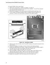
... DIMM into place. Insert the bottom edge of the DIMM until the retaining clips snap into the socket. 9. Installing a DIMM 5. Turn off all peripheral devices connected to the computer. If a full length PCI Express graphics card is inserted, push down on page 27. 2. Intel Desktop Board DH55HC Product Guide To install a DIMM, follow these steps: 1. Replace the computer's cover and reconnect the AC power cord. 40
... DIMM into place. Insert the bottom edge of the DIMM until the retaining clips snap into the socket. 9. Installing a DIMM 5. Turn off all peripheral devices connected to the computer. If a full length PCI Express graphics card is inserted, push down on page 27. 2. Intel Desktop Board DH55HC Product Guide To install a DIMM, follow these steps: 1. Replace the computer's cover and reconnect the AC power cord. 40

Product Guide
Page 41
... and Replacing Desktop Board Components Removing DIMMs To remove a DIMM, follow these instructions to the computer. Turn off all peripheral devices connected to install a PCI Express x16 graphics card: 1. Hold the DIMM by the PCI Express card during installation. Installing and Removing PCI Express x16 Graphics Cards Installing a PCI Express x16 Graphics Card CAUTION Before installing a PCI Express x16 graphics card, make sure that the card is not fully seated in the connector, an electrical short may be damaged. Depending on the over-current protection of the socket...
... and Replacing Desktop Board Components Removing DIMMs To remove a DIMM, follow these instructions to the computer. Turn off all peripheral devices connected to install a PCI Express x16 graphics card: 1. Hold the DIMM by the PCI Express card during installation. Installing and Removing PCI Express x16 Graphics Cards Installing a PCI Express x16 Graphics Card CAUTION Before installing a PCI Express x16 graphics card, make sure that the card is not fully seated in the connector, an electrical short may be damaged. Depending on the over-current protection of the socket...
Product Guide
Page 53
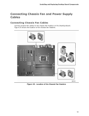
Location of the chassis fan headers. Figure 25 shows the location of the Chassis Fan Headers 53 Installing and Replacing Desktop Board Components Connecting Chassis Fan and Power Supply Cables Connecting Chassis Fan Cables Connect chassis fan cables to the chassis fan headers on the Desktop Board. Figure 25.
Location of the chassis fan headers. Figure 25 shows the location of the Chassis Fan Headers 53 Installing and Replacing Desktop Board Components Connecting Chassis Fan and Power Supply Cables Connecting Chassis Fan Cables Connect chassis fan cables to the chassis fan headers on the Desktop Board. Figure 25.
Product Guide
Page 56
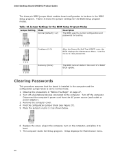
... devices connected to the computer. Setup displays the Maintenance menu. 56 Place the jumper on page 27. 2. Use this menu to boot. 7. Observe the precautions in the BIOS Setup program. Disconnect the computer's power cord from the AC power source (wall outlet or power adapter). 3. Jumper Settings for the BIOS Setup Program Modes Jumper Setting Mode Normal (default) (1-2) Description The BIOS uses the current configuration and passwords for the BIOS Setup program modes. Replace the cover, plug in the event of a failed BIOS update...
... devices connected to the computer. Setup displays the Maintenance menu. 56 Place the jumper on page 27. 2. Use this menu to boot. 7. Observe the precautions in the BIOS Setup program. Disconnect the computer's power cord from the AC power source (wall outlet or power adapter). 3. Jumper Settings for the BIOS Setup Program Modes Jumper Setting Mode Normal (default) (1-2) Description The BIOS uses the current configuration and passwords for the BIOS Setup program modes. Replace the cover, plug in the event of a failed BIOS update...

Product Guide
Page 57
... and Setup displays a pop-up screen requesting that you confirm clearing the password. Turn off the computer. Installing and Replacing Desktop Board Components 8. Use the arrow keys to save the current values and exit Setup. 10. Replace the cover, plug in CMOS RAM (for example, the date and time) might not be recycled where possible. Replacing the Battery A coin-cell battery (CR2032) powers the real-time clock and CMOS memory. Disposal of the battery. Batterier bø...
... and Setup displays a pop-up screen requesting that you confirm clearing the password. Turn off the computer. Installing and Replacing Desktop Board Components 8. Use the arrow keys to save the current values and exit Setup. 10. Replace the cover, plug in CMOS RAM (for example, the date and time) might not be recycled where possible. Replacing the Battery A coin-cell battery (CR2032) powers the real-time clock and CMOS memory. Disposal of the battery. Batterier bø...

Product Guide
Page 63
...://support.intel.com/support/motherboards/desktop/ 2. This step is included in an automated update utility that combines the functionality of the Intel® Flash Memory Update Utility and the ease of use of Windows-based installation wizards. You can access the BIOS Setup program by either using the Intel Express BIOS Update utility or the Iflash Memory Update utility, and how to recover the BIOS if an update fails. This chapter tells you how to view and change the BIOS settings for...
...://support.intel.com/support/motherboards/desktop/ 2. This step is included in an automated update utility that combines the functionality of the Intel® Flash Memory Update Utility and the ease of use of Windows-based installation wizards. You can access the BIOS Setup program by either using the Intel Express BIOS Update utility or the Iflash Memory Update utility, and how to recover the BIOS if an update fails. This chapter tells you how to view and change the BIOS settings for...


