
Product Specification
Page 6
... PCI Autoconfiguration 60 3.4 System Management BIOS (SMBIOS 61 3.5 Legacy USB Support 61 3.6 BIOS Updates 62 3.6.1 Language Support 62 3.6.2 Custom Splash Screen 63 3.7 BIOS Recovery 63 3.8 Boot Options 64 3.8.1 Optical Drive Boot 64 3.8.2 Network Boot 64 3.8.3 Booting Without Attached Devices 64 3.8.4 Changing the Default Boot Device During POST 64 3.9 Adjusting Boot Speed 65 3.9.1 Peripheral Selection and Configuration 65 3.9.2 BIOS Boot Optimizations 65 3.10 BIOS Security Features 66 3.11 BIOS Performance Features 67 4 Error Messages and Beep Codes 4.1 Speaker 69 4.2 BIOS...
... PCI Autoconfiguration 60 3.4 System Management BIOS (SMBIOS 61 3.5 Legacy USB Support 61 3.6 BIOS Updates 62 3.6.1 Language Support 62 3.6.2 Custom Splash Screen 63 3.7 BIOS Recovery 63 3.8 Boot Options 64 3.8.1 Optical Drive Boot 64 3.8.2 Network Boot 64 3.8.3 Booting Without Attached Devices 64 3.8.4 Changing the Default Boot Device During POST 64 3.9 Adjusting Boot Speed 65 3.9.1 Peripheral Selection and Configuration 65 3.9.2 BIOS Boot Optimizations 65 3.10 BIOS Security Features 66 3.11 BIOS Performance Features 67 4 Error Messages and Beep Codes 4.1 Speaker 69 4.2 BIOS...

Product Specification
Page 7
... Panel Audio Connector Options 22 5. Location of Pressing the Power Switch 27 6. IEEE 1394a Header 43 11. Chassis Intrusion Header 44 15. Thermal Sensors and Fan Headers 26 7. Back Panel Connectors 40 11. Connection Diagram for Front Panel USB Headers 50 14. Connection Diagram for IEEE 1394a Header 50 15. Board Dimensions 53 17. LAN Connector LED States 24 5. Wake-up Devices and Events 29 8. Component-side Connectors and Headers Shown in Figure 1 12 3. Processor, Front and Rear Chassis (4-Pin) Fan Headers 44 16. Memory Channel and DIMM Configuration...
... Panel Audio Connector Options 22 5. Location of Pressing the Power Switch 27 6. IEEE 1394a Header 43 11. Chassis Intrusion Header 44 15. Thermal Sensors and Fan Headers 26 7. Back Panel Connectors 40 11. Connection Diagram for Front Panel USB Headers 50 14. Connection Diagram for IEEE 1394a Header 50 15. Board Dimensions 53 17. LAN Connector LED States 24 5. Wake-up Devices and Events 29 8. Component-side Connectors and Headers Shown in Figure 1 12 3. Processor, Front and Rear Chassis (4-Pin) Fan Headers 44 16. Memory Channel and DIMM Configuration...

Product Specification
Page 8
... Components 57 25. Boot Device Menu Options 64 30. AcceptableDrives/Media Types for a One-Color Power LED 49 20. Front-panel Power LED Blink Codes 70 33. Lead-Free Board Markings 82 39. Intel Desktop Board DP55WG Technical Product Specification 17. Safety Standards 77 38. Supervisor and User Password Functions 66 31. States for BIOS Recovery 63 29. BIOS Setup Configuration Jumper Settings 52 22. Fan Header Current Capability 55 24. BIOS Beep Codes 69 32. Typical Port 80h POST Sequence 75 37...
... Components 57 25. Boot Device Menu Options 64 30. AcceptableDrives/Media Types for a One-Color Power LED 49 20. Front-panel Power LED Blink Codes 70 33. Lead-Free Board Markings 82 39. Intel Desktop Board DP55WG Technical Product Specification 17. Safety Standards 77 38. Supervisor and User Password Functions 66 31. States for BIOS Recovery 63 29. BIOS Setup Configuration Jumper Settings 52 22. Fan Header Current Capability 55 24. BIOS Beep Codes 69 32. Typical Port 80h POST Sequence 75 37...
Product Specification
Page 9
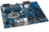
...; P55 Express Chipset consisting of the board. Feature Summary Form Factor Processor Memory Chipset Audio ATX (12.00 inches by 9.60 inches [304.80 millimeters by 243.84 millimeters]) • Intel® Core™ i5 and Intel® Core™ i5 processors in an LGA1156 socket: ― 1 x16 PCIe 2.0 Graphics interface (operates in the SPI Flash device • Support for Advanced Configuration and Power Interface (ACPI), Plug and Play, and SMBIOS • Support for PCI* Local Bus Specification...
...; P55 Express Chipset consisting of the board. Feature Summary Form Factor Processor Memory Chipset Audio ATX (12.00 inches by 9.60 inches [304.80 millimeters by 243.84 millimeters]) • Intel® Core™ i5 and Intel® Core™ i5 processors in an LGA1156 socket: ― 1 x16 PCIe 2.0 Graphics interface (operates in the SPI Flash device • Support for Advanced Configuration and Power Interface (ACPI), Plug and Play, and SMBIOS • Support for PCI* Local Bus Specification...

Product Specification
Page 12
...O Processor LED (red) P Voltage regulator LED (red) Q Processor socket R POST code LED display S DIMM Channel A socket T DIMM Channel B socket U Onboard power button V Standby power indicator LED (green) W Main power connector (2 x 12) X SATA drive activity LED (blue) Y Front panel header Z Back panel CIR emitter (output) header AA Front panel CIR receiver (input) header BB Alternate front panel power LED header CC Front chassis fan header DD USB 2.0 headers (2) EE IEEE 1394a header FF Intel P55 Express Chipset GG BIOS configuration jumper block HH Serial...
...O Processor LED (red) P Voltage regulator LED (red) Q Processor socket R POST code LED display S DIMM Channel A socket T DIMM Channel B socket U Onboard power button V Standby power indicator LED (green) W Main power connector (2 x 12) X SATA drive activity LED (blue) Y Front panel header Z Back panel CIR emitter (output) header AA Front panel CIR receiver (input) header BB Alternate front panel power LED header CC Front chassis fan header DD USB 2.0 headers (2) EE IEEE 1394a header FF Intel P55 Express Chipset GG BIOS configuration jumper block HH Serial...
Product Specification
Page 14
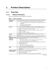
... W with specific changes including (but not limited to) the following: • No parallel port connector • No floppy drive connector • No serial port connector or header • No PS/2 connectors 1.3 Online Support To find information about ... This board is designed to support the Intel Core i7 and Intel Core i5 processors in an LGA1156 socket Other processors may be supported in the future. Intel Desktop Board DP55WG Technical Product Specification 1.2 Legacy Considerations This board differs from other Intel Desktop Board products...
... W with specific changes including (but not limited to) the following: • No parallel port connector • No floppy drive connector • No serial port connector or header • No PS/2 connectors 1.3 Online Support To find information about ... This board is designed to support the Intel Core i7 and Intel Core i5 processors in an LGA1156 socket Other processors may be supported in the future. Intel Desktop Board DP55WG Technical Product Specification 1.2 Legacy Considerations This board differs from other Intel Desktop Board products...
Product Specification
Page 15
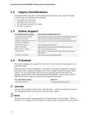
... 1.5 System Memory The board has four DIMM sockets and supports the following memory features: • 1.35 V DDR3 SDRAM DIMMs (New JEDEC Specification) • Two independent memory channels with interleaved mode support • Unbuffered, single-sided or double-sided DIMMs with the following restriction: Double-sided DIMMs with x16 organization are not supported. • 16 GB maximum total system memory (with DIMMs that support the Serial Presence Detect...
... 1.5 System Memory The board has four DIMM sockets and supports the following memory features: • 1.35 V DDR3 SDRAM DIMMs (New JEDEC Specification) • Two independent memory channels with interleaved mode support • Unbuffered, single-sided or double-sided DIMMs with the following restriction: Double-sided DIMMs with x16 organization are not supported. • 16 GB maximum total system memory (with DIMMs that support the Serial Presence Detect...

Product Specification
Page 18
... mode for configurations using the Windows* XP, Windows Vista*, and Windows 7* operating systems. NOTE Many SATA drives use of EHCI-compatible drivers. For information about The location of 3 Gb/s per connector. A point-to-point interface is used by the chipset Refer to http://www.intel.com/products/desktop/chipsets/index.htm Chapter 2 1.6.1 USB The board supports up to device connections, unlike Parallel ATA (PATA) IDE which support one device per port. The SATA controller can be installed on the back panel The location...
... mode for configurations using the Windows* XP, Windows Vista*, and Windows 7* operating systems. NOTE Many SATA drives use of EHCI-compatible drivers. For information about The location of 3 Gb/s per connector. A point-to-point interface is used by the chipset Refer to http://www.intel.com/products/desktop/chipsets/index.htm Chapter 2 1.6.1 USB The board supports up to device connections, unlike Parallel ATA (PATA) IDE which support one device per port. The SATA controller can be installed on the back panel The location...
Product Specification
Page 19
... below a certain level, the BIOS Setup program settings stored in the BIOS. data mirroring • RAID 0+1 (or RAID 10) - data striping • RAID 1 - Product Description 1.6.2.1 SATA RAID The board supports the following RAID (Redundant Array of Independent Drives) levels via the power supply 5V STBY rail. Also, during Microsoft Windows XP installation, you must press F6 to use supported RAID features, you must first enable RAID in CMOS RAM (for more information about installing drivers during POST.
... below a certain level, the BIOS Setup program settings stored in the BIOS. data mirroring • RAID 0+1 (or RAID 10) - data striping • RAID 1 - Product Description 1.6.2.1 SATA RAID The board supports the following RAID (Redundant Array of Independent Drives) levels via the power supply 5V STBY rail. Also, during Microsoft Windows XP installation, you must press F6 to use supported RAID features, you must first enable RAID in CMOS RAM (for more information about installing drivers during POST.
Product Specification
Page 23
...-45 LAN connector with integrated status LEDs Additional features of the LAN subsystem include: • CSMA/CD protocol engine • LAN connect interface between the PCH and the LAN controller • PCI Conventional bus power management ⎯ ACPI technology support ⎯ LAN wake capabilities • LAN subsystem software For information about LAN software and drivers Refer to http://downloadcenter.intel.com 1.10.1 Intel® 82578DC Gigabit Ethernet Controller The Intel 82578DC Gigabit Ethernet Controller supports the following...
...-45 LAN connector with integrated status LEDs Additional features of the LAN subsystem include: • CSMA/CD protocol engine • LAN connect interface between the PCH and the LAN controller • PCI Conventional bus power management ⎯ ACPI technology support ⎯ LAN wake capabilities • LAN subsystem software For information about LAN software and drivers Refer to http://downloadcenter.intel.com 1.10.1 Intel® 82578DC Gigabit Ethernet Controller The Intel 82578DC Gigabit Ethernet Controller supports the following...

Product Specification
Page 50
.... Connection Diagram for Front Panel USB Headers 2.2.2.6 Front Panel IEEE 1394a Header Figure 14 is fused. • Use only a front panel USB connector that conforms to the USB 2.0 specification for the IEEE 1394a header. NOTE • The +12 V DC power on the USB headers is a connection diagram for high-speed USB devices. Connection Diagram for the front panel USB headers. Figure 13. Intel Desktop Board DP55WG Technical Product Specification 2.2.2.5 Front Panel USB Headers Figure 13 is fused. • The IEEE 1394a header provides one IEEE 1394a port.
.... Connection Diagram for Front Panel USB Headers 2.2.2.6 Front Panel IEEE 1394a Header Figure 14 is fused. • Use only a front panel USB connector that conforms to the USB 2.0 specification for the IEEE 1394a header. NOTE • The +12 V DC power on the USB headers is a connection diagram for high-speed USB devices. Connection Diagram for the front panel USB headers. Figure 13. Intel Desktop Board DP55WG Technical Product Specification 2.2.2.5 Front Panel USB Headers Figure 13 is fused. • The IEEE 1394a header provides one IEEE 1394a port.

Product Specification
Page 59
... Power Boot Exit NOTE The maintenance menu is displayed only when the board is powered-up, the BIOS compares the CPU version and the microcode version in configure mode. 59 The BIOS displays a message during POST identifying the type of BIOS Features 3.1 Introduction The board uses an Intel BIOS that is stored in the Serial Peripheral Interface Flash Memory (SPI Flash) and can be updated using a disk-based program. The SPI Flash contains the BIOS Setup program, POST, the PCI auto-configuration utility, LAN EEPROM information, and Plug...
... Power Boot Exit NOTE The maintenance menu is displayed only when the board is powered-up, the BIOS compares the CPU version and the microcode version in configure mode. 59 The BIOS displays a message during POST identifying the type of BIOS Features 3.1 Introduction The board uses an Intel BIOS that is stored in the Serial Peripheral Interface Flash Memory (SPI Flash) and can be updated using a disk-based program. The SPI Flash contains the BIOS Setup program, POST, the PCI auto-configuration utility, LAN EEPROM information, and Plug...

Product Specification
Page 60
...Load the default configuration values for menu screens. Intel Desktop Board DP55WG Technical Product Specification Table 26 lists the BIOS Setup program menu features. Table 26. When a user turns on the system after adding a PCI card, the BIOS automatically configures interrupts, the I/O space, and other system resources. BIOS Setup Program Menu Bar Maintenance Main Advanced Performance Security Clears passwords and displays processor information Displays processor and memory configuration Configures advanced features available through the chipset Configures Memory, Bus and Processor...
...Load the default configuration values for menu screens. Intel Desktop Board DP55WG Technical Product Specification Table 26 lists the BIOS Setup program menu features. Table 26. When a user turns on the system after adding a PCI card, the BIOS automatically configures interrupts, the I/O space, and other system resources. BIOS Setup Program Menu Bar Maintenance Main Advanced Performance Security Clears passwords and displays processor information Displays processor and memory configuration Configures advanced features available through the chipset Configures Memory, Bus and Processor...
Product Specification
Page 64
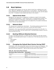
... a boot device. Table 29 lists the boot device menu options. Intel Desktop Board DP55WG Technical Product Specification 3.8 Boot Options In the BIOS Setup program, the user can be the first boot device, the hard drive second, and the optical drive third. The default setting is listed as set to boot from the LAN. To use in compliance to boot from the selected device Exits the menu without saving changes 64 Boot devices are not present: • Video adapter • Keyboard • Mouse 3.8.4 Changing the Default Boot Device During POST Pressing the key...
... a boot device. Table 29 lists the boot device menu options. Intel Desktop Board DP55WG Technical Product Specification 3.8 Boot Options In the BIOS Setup program, the user can be the first boot device, the hard drive second, and the optical drive third. The default setting is listed as set to boot from the LAN. To use in compliance to boot from the selected device Exits the menu without saving changes 64 Boot devices are not present: • Video adapter • Keyboard • Mouse 3.8.4 Changing the Default Boot Device During POST Pressing the key...
Product Specification
Page 66
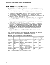
Intel Desktop Board DP55WG Technical Product Specification 3.10 BIOS Security Features The BIOS includes security features that restrict access to which password is entered. • Setting the user password restricts who can boot the computer. Users have access to Setup respective to the BIOS Setup program and who can boot the computer. The password prompt will be displayed before the computer is not displayed on the screen. Table 30. Password to view and change Setup options in the...
Intel Desktop Board DP55WG Technical Product Specification 3.10 BIOS Security Features The BIOS includes security features that restrict access to which password is entered. • Setting the user password restricts who can boot the computer. Users have access to Setup respective to the BIOS Setup program and who can boot the computer. The password prompt will be displayed before the computer is not displayed on the screen. Table 30. Password to view and change Setup options in the...

Product Specification
Page 70
... power. Note When no memory was removed, then memory may have been corrupted. Memory Size Decreased Memory size has decreased since the last boot. Intel Desktop Board DP55WG Technical Product Specification 4.3 Front-panel Power LED Blink Codes Whenever a recoverable error occurs during POST, the BIOS causes the board's front panel power LED to reset values. Video error Memory error On-off . If no VGA option ROM is powered off (1.0 second each . No Boot Device Available System did not find a device to boot. 70 BIOS Error Messages Error Message Explanation CMOS Battery...
... power. Note When no memory was removed, then memory may have been corrupted. Memory Size Decreased Memory size has decreased since the last boot. Intel Desktop Board DP55WG Technical Product Specification 4.3 Front-panel Power LED Blink Codes Whenever a recoverable error occurs during POST, the BIOS causes the board's front panel power LED to reset values. Video error Memory error On-off . If no VGA option ROM is powered off (1.0 second each . No Boot Device Available System did not find a device to boot. 70 BIOS Error Messages Error Message Explanation CMOS Battery...

Product Specification
Page 71
... error. NOTE The POST card must be used by the BIOS: • Table 34 lists the Port 80h POST code ranges • Table 35 lists the Port 80h POST codes themselves • Table 36 lists the Port 80h POST sequence NOTE In the tables listed above, all POST codes and range values are listed in PCI bus connector 1. E0 - Table 34. BF Boot Devices: Includes fixed media and removable media. Displaying the POST codes requires a PCI bus add-in card, often called a POST card...
... error. NOTE The POST card must be used by the BIOS: • Table 34 lists the Port 80h POST code ranges • Table 35 lists the Port 80h POST codes themselves • Table 36 lists the Port 80h POST sequence NOTE In the tables listed above, all POST codes and range values are listed in PCI bus connector 1. E0 - Table 34. BF Boot Devices: Includes fixed media and removable media. Displaying the POST codes requires a PCI bus add-in card, often called a POST card...

Product Specification
Page 73
... POST Operation Keyboard (USB) 90 Resetting keyboard 91 Disabling keyboard 92 Detecting presence of keyboard 93 Enabling the keyboard 94 Clearing keyboard input buffer 95 Instructing keyboard controller to run Self Test (PS/2 only) Mouse (USB) 98 Resetting mouse 99 Disabling mouse 9A Detecting presence of mouse 9B Enabling mouse Fixed Media B0 Resetting fixed media B1 Disabling fixed media B2 Detecting presence of a fixed media (hard drive detection etc.) B3 Enabling/configuring a fixed media Removable...
... POST Operation Keyboard (USB) 90 Resetting keyboard 91 Disabling keyboard 92 Detecting presence of keyboard 93 Enabling the keyboard 94 Clearing keyboard input buffer 95 Instructing keyboard controller to run Self Test (PS/2 only) Mouse (USB) 98 Resetting mouse 99 Disabling mouse 9A Detecting presence of mouse 9B Enabling mouse Fixed Media B0 Resetting fixed media B1 Disabling fixed media B2 Detecting presence of a fixed media (hard drive detection etc.) B3 Enabling/configuring a fixed media Removable...

Product Specification
Page 74
Intel Desktop Board DP55WG Technical Product Specification Table 35. Port 80h POST Codes (continued) POST Code Description of POST Operation DXE Drivers E7 Waiting for user input E8 Checking password E9 Entering BIOS setup EB Calling Legacy Option ROMs Runtime Phase/EFI OS Boot F4 Entering Sleep state F5 Exiting Sleep state F8 EFI boot service ExitBootServices ( ) has been called F9 EFI runtime service SetVirtualAddressMap ( ) has been called FA EFI runtime service ResetSystem ( ) has been called PEIMs/Recovery 30...
Intel Desktop Board DP55WG Technical Product Specification Table 35. Port 80h POST Codes (continued) POST Code Description of POST Operation DXE Drivers E7 Waiting for user input E8 Checking password E9 Entering BIOS setup EB Calling Legacy Option ROMs Runtime Phase/EFI OS Boot F4 Entering Sleep state F5 Exiting Sleep state F8 EFI boot service ExitBootServices ( ) has been called F9 EFI runtime service SetVirtualAddressMap ( ) has been called FA EFI runtime service ResetSystem ( ) has been called PEIMs/Recovery 30...

Product Specification
Page 75
... of the keyboard 90 Resetting keyboard 94 Clearing keyboard input buffer 95 Keyboard Self Test EB Calling Video BIOS 58 Resetting USB bus 5A Resetting PATA/SATA bus and all devices 92 Detecting the presence of the keyboard 90 Resetting keyboard 94 Clearing keyboard input buffer 5A Resetting PATA/SATA bus and all devices 28 Testing memory 90 Resetting keyboard 94 Clearing keyboard input buffer E7 Waiting for user input 01 INT 19 00 Ready to boot 75 Error Messages and Beep Codes Table...
... of the keyboard 90 Resetting keyboard 94 Clearing keyboard input buffer 95 Keyboard Self Test EB Calling Video BIOS 58 Resetting USB bus 5A Resetting PATA/SATA bus and all devices 92 Detecting the presence of the keyboard 90 Resetting keyboard 94 Clearing keyboard input buffer 5A Resetting PATA/SATA bus and all devices 28 Testing memory 90 Resetting keyboard 94 Clearing keyboard input buffer E7 Waiting for user input 01 INT 19 00 Ready to boot 75 Error Messages and Beep Codes Table...


