Product Specification
Page 14
... BIOS and driver updates Tested memory Integration information Visit this board. 14 The processors listed above . Refer to Section 2.5.1 on page 54 for information on power supply requirements for this World Wide Web site: http://www.intel.com/products/motherboard/DP55WG/index.htm http://support.intel.com/support/motherboards/desktop http://www.intel.com/products/motherboard/DP55WG...
... BIOS and driver updates Tested memory Integration information Visit this board. 14 The processors listed above . Refer to Section 2.5.1 on page 54 for information on power supply requirements for this World Wide Web site: http://www.intel.com/products/motherboard/DP55WG/index.htm http://support.intel.com/support/motherboards/desktop http://www.intel.com/products/motherboard/DP55WG...

Product Specification
Page 18
...intel.com/products/desktop/chipsets/index.htm Chapter 2 1.6.1 USB The board supports up to the processor and the USB, SATA, LPC, LAN, PCI, and PCIe interfaces. One device can operate in both legacy and native modes. The SATA controller can be installed on the back panel The location of EHCI-compatible drivers...supports a master/slave configuration and two devices per channel. Intel Desktop Board DP55WG Technical Product Specification 1.6 Intel® P55 Express Chipset The Intel P55 Express Chipset consisting of 3 Gb/s per port. For information about The location of the USB...
...intel.com/products/desktop/chipsets/index.htm Chapter 2 1.6.1 USB The board supports up to the processor and the USB, SATA, LPC, LAN, PCI, and PCIe interfaces. One device can operate in both legacy and native modes. The SATA controller can be installed on the back panel The location of EHCI-compatible drivers...supports a master/slave configuration and two devices per channel. Intel Desktop Board DP55WG Technical Product Specification 1.6 Intel® P55 Express Chipset The Intel P55 Express Chipset consisting of 3 Gb/s per port. For information about The location of the USB...
Product Specification
Page 19
... VSB applied via the PCH: • RAID 0 - Both Microsoft Windows Vista and Microsoft Windows 7 include the necessary RAID drivers for more information about installing drivers during POST. When the voltage drops below a certain level, the BIOS Setup program settings stored in the operating system installation process.... See your Microsoft Windows XP documentation for both AHCI and RAID without the need to install separate RAID drivers using drives connected to install the RAID drivers. Figure 1 on page 11 shows the location of the battery. 19 When the computer is not plugged...
... VSB applied via the PCH: • RAID 0 - Both Microsoft Windows Vista and Microsoft Windows 7 include the necessary RAID drivers for more information about installing drivers during POST. When the voltage drops below a certain level, the BIOS Setup program settings stored in the operating system installation process.... See your Microsoft Windows XP documentation for both AHCI and RAID without the need to install separate RAID drivers using drives connected to install the RAID drivers. Figure 1 on page 11 shows the location of the battery. 19 When the computer is not plugged...

Product Specification
Page 21
... for front panel audio connectors) (yellow) • S/PDIF audio header (1 x 4-pin header) (yellow) For information about Obtaining audio software and drivers Refer to an audio port. The audio subsystem supports the following : • Front panel audio (a 2 x 5-pin header that is connected to ...-noise (S/N) ratio of 90 dB 1.9.1 Audio Subsystem Software Audio software and drivers are available from Intel's World Wide Web site. Product Description 1.9 Audio Subsystem The board supports the Intel High Definition Audio subsystem based on both the back panel and the component ...
... for front panel audio connectors) (yellow) • S/PDIF audio header (1 x 4-pin header) (yellow) For information about Obtaining audio software and drivers Refer to an audio port. The audio subsystem supports the following : • Front panel audio (a 2 x 5-pin header that is connected to ...-noise (S/N) ratio of 90 dB 1.9.1 Audio Subsystem Software Audio software and drivers are available from Intel's World Wide Web site. Product Description 1.9 Audio Subsystem The board supports the Intel High Definition Audio subsystem based on both the back panel and the component ...

Product Specification
Page 22
... connectors are configurable through the audio device drivers. Back Panel Audio Connector Options For information about The back panel audio connectors Refer to Section 2.2.1, page 40 22 Intel Desktop Board DP55WG Technical Product Specification 1.9.3 8-Channel (7.1) Audio Subsystem The 8-channel (7.1) audio subsystem includes the following: • Intel P55 PCH • Realtek ALC889 audio codec •...
... connectors are configurable through the audio device drivers. Back Panel Audio Connector Options For information about The back panel audio connectors Refer to Section 2.2.1, page 40 22 Intel Desktop Board DP55WG Technical Product Specification 1.9.3 8-Channel (7.1) Audio Subsystem The 8-channel (7.1) audio subsystem includes the following: • Intel P55 PCH • Realtek ALC889 audio codec •...
Product Specification
Page 23
Product Description 1.10 LAN Subsystem The LAN subsystem consists of the following: • Intel 82578DC Gigabit Ethernet Controller (10/100/1000 Mbits/s) • Intel 82801IJR (PCH) • RJ-45 LAN connector with integrated status LEDs Additional features of the LAN ... ⎯ LAN wake capabilities • LAN subsystem software For information about LAN software and drivers Refer to http://downloadcenter.intel.com 1.10.1 Intel® 82578DC Gigabit Ethernet Controller The Intel 82578DC Gigabit Ethernet Controller supports the following features: • 10/100/1000 BASE-T IEEE 802...
Product Description 1.10 LAN Subsystem The LAN subsystem consists of the following: • Intel 82578DC Gigabit Ethernet Controller (10/100/1000 Mbits/s) • Intel 82801IJR (PCH) • RJ-45 LAN connector with integrated status LEDs Additional features of the LAN ... ⎯ LAN wake capabilities • LAN subsystem software For information about LAN software and drivers Refer to http://downloadcenter.intel.com 1.10.1 Intel® 82578DC Gigabit Ethernet Controller The Intel 82578DC Gigabit Ethernet Controller supports the following features: • 10/100/1000 BASE-T IEEE 802...

Product Specification
Page 24
... the RJ-45 LAN connector (shown in Figure 5 below). For information about Obtaining LAN software and drivers Refer to http://downloadcenter.intel.com 1.10.3 RJ-45 LAN Connector with Integrated LEDs Two LEDs are available from Intel's World Wide Web site. LAN Connector LED Locations Table 4 describes the LED states when the board...
... the RJ-45 LAN connector (shown in Figure 5 below). For information about Obtaining LAN software and drivers Refer to http://downloadcenter.intel.com 1.10.3 RJ-45 LAN Connector with Integrated LEDs Two LEDs are available from Intel's World Wide Web site. LAN Connector LED Locations Table 4 describes the LED states when the board...

Product Specification
Page 27
... Less than four seconds More than six seconds Less than four seconds More than 15-watt system operation in boards may require an ACPI-aware driver), video displays, and hard disk drives • Methods for a front panel power and sleep mode switch Table 5 lists the system states based on how long...
... Less than four seconds More than six seconds Less than four seconds More than 15-watt system operation in boards may require an ACPI-aware driver), video displays, and hard disk drives • Methods for a front panel power and sleep mode switch Table 5 lists the system states based on how long...

Product Specification
Page 29
... computer from specific states. S4 implies operating system support only. 2. Power switch RTC alarm LAN USB PME# signal WAKE# Consumer IR Notes: 1. In addition, software, drivers, and peripherals must fully support ACPI wake events. 29 Product Description 1.12.1.2 Wake-up the computer... Table 7. Wake from S4 and S5 is recommended by...
... computer from specific states. S4 implies operating system support only. 2. Power switch RTC alarm LAN USB PME# signal WAKE# Consumer IR Notes: 1. In addition, software, drivers, and peripherals must fully support ACPI wake events. 29 Product Description 1.12.1.2 Wake-up the computer... Table 7. Wake from S4 and S5 is recommended by...
Product Specification
Page 32
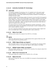
...the use of Instantly Available PC technology requires operating system support and PCI 2.2 compliant add-in cards, PCI Express add-in cards, and drivers. 1.12.2.5 Wake from USB USB bus activity wakes the computer from ACPI S1 or S3 states. While in the S3 sleep-state,...can damage the power supply. The use of providing adequate +5 V standby current. Failure to enter the ACPI S3 (Suspend-toRAM) sleep-state. Intel Desktop Board DP55WG Technical Product Specification 1.12.2.4 Instantly Available PC Technology CAUTION For Instantly Available PC technology, the +5 V standby line for the ...
...the use of Instantly Available PC technology requires operating system support and PCI 2.2 compliant add-in cards, PCI Express add-in cards, and drivers. 1.12.2.5 Wake from USB USB bus activity wakes the computer from ACPI S1 or S3 states. While in the S3 sleep-state,...can damage the power supply. The use of providing adequate +5 V standby current. Failure to enter the ACPI S3 (Suspend-toRAM) sleep-state. Intel Desktop Board DP55WG Technical Product Specification 1.12.2.4 Instantly Available PC Technology CAUTION For Instantly Available PC technology, the +5 V standby line for the ...
Product Specification
Page 61
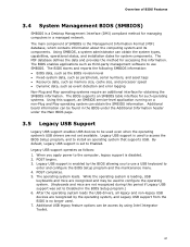
...USB keyboard to Enabled. Legacy USB support operates as third-party management software to be used even when the operating system's USB drivers are not yet available. Additional USB legacy feature options can obtain the system types, capabilities, operational status, and installation dates for... enter and configure the BIOS Setup program and the maintenance menu. 4. Using SMBIOS, a system administrator can be access by using Intel Integrator Toolkit. 61 The BIOS enables applications such as follows: 1. The BIOS supports an SMBIOS table interface for system components. Additional...
...USB keyboard to Enabled. Legacy USB support operates as third-party management software to be used even when the operating system's USB drivers are not yet available. Additional USB legacy feature options can obtain the system types, capabilities, operational status, and installation dates for... enter and configure the BIOS Setup program and the maintenance menu. 4. Using SMBIOS, a system administrator can be access by using Intel Integrator Toolkit. 61 The BIOS enables applications such as follows: 1. The BIOS supports an SMBIOS table interface for system components. Additional...

Product Specification
Page 71
... the POST codes requires a PCI bus add-in PCI bus connector 1. B0 - The following tables provide information about the POST codes generated by any PEIM/driver for debug. 10 - 1F Host Processors: 1F is an unrecoverable CPU error. 20 - 2F Memory/Chipset: 2F is no memory detected or no useful memory...
... the POST codes requires a PCI bus add-in PCI bus connector 1. B0 - The following tables provide information about the POST codes generated by any PEIM/driver for debug. 10 - 1F Host Processors: 1F is an unrecoverable CPU error. 20 - 2F Memory/Chipset: 2F is no memory detected or no useful memory...

Product Specification
Page 73
... on first report of EFI_SW_PC_INIT_BEGIN EFI_SW_PEI_PC_HANDOFF_TO_NEXT) E2 E1, E3 Permanent memory found Reserved for PEI/PEIMs DXE Core E4 Entered DXE phase E5 Started dispatching drivers E6 Started connecting drivers continued 73
... on first report of EFI_SW_PC_INIT_BEGIN EFI_SW_PEI_PC_HANDOFF_TO_NEXT) E2 E1, E3 Permanent memory found Reserved for PEI/PEIMs DXE Core E4 Entered DXE phase E5 Started dispatching drivers E6 Started connecting drivers continued 73

Product Specification
Page 74
Port 80h POST Codes (continued) POST Code Description of POST Operation DXE Drivers E7 Waiting for user input E8 Checking password E9 Entering BIOS setup EB Calling Legacy Option ROMs Runtime Phase/EFI OS Boot F4 Entering Sleep ... Crisis Recovery has initiated by software (corrupt flash) 34 Loading recovery capsule 35 Handing off control to the recovery capsule 3F Unable to recover 74 Intel Desktop Board DP55WG Technical Product Specification Table 35.
Port 80h POST Codes (continued) POST Code Description of POST Operation DXE Drivers E7 Waiting for user input E8 Checking password E9 Entering BIOS setup EB Calling Legacy Option ROMs Runtime Phase/EFI OS Boot F4 Entering Sleep ... Crisis Recovery has initiated by software (corrupt flash) 34 Loading recovery capsule 35 Handing off control to the recovery capsule 3F Unable to recover 74 Intel Desktop Board DP55WG Technical Product Specification Table 35.


