Product Specification
Page 8
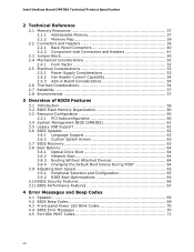
...3.5 Legacy USB Support 61 3.6 BIOS Updates 62 3.6.1 Language Support 62 3.6.2 Custom Splash Screen 63 3.7 BIOS Recovery 63 3.8 Boot Options 64 3.8.1 Optical Drive Boot 64 3.8.2 Network Boot 64 3.8.3 Booting Without Attached Devices 64 3.8.4 Changing the Default Boot Device During POST 64 3.9 Adjusting Boot Speed 65 3.9.1 Peripheral Selection and Configuration 65 3.9.2 BIOS Boot Optimizations 65 3.10 BIOS Security Features 66 3.11 BIOS Performance Features 67 4 Error Messages and Beep Codes 4.1 Speaker 69 4.2 BIOS Beep Codes 69 4.3 Front-panel Power LED Blink Codes 70 4.4 BIOS...
...3.5 Legacy USB Support 61 3.6 BIOS Updates 62 3.6.1 Language Support 62 3.6.2 Custom Splash Screen 63 3.7 BIOS Recovery 63 3.8 Boot Options 64 3.8.1 Optical Drive Boot 64 3.8.2 Network Boot 64 3.8.3 Booting Without Attached Devices 64 3.8.4 Changing the Default Boot Device During POST 64 3.9 Adjusting Boot Speed 65 3.9.1 Peripheral Selection and Configuration 65 3.9.2 BIOS Boot Optimizations 65 3.10 BIOS Security Features 66 3.11 BIOS Performance Features 67 4 Error Messages and Beep Codes 4.1 Speaker 69 4.2 BIOS Beep Codes 69 4.3 Front-panel Power LED Blink Codes 70 4.4 BIOS...

Product Specification
Page 9
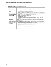
...the Power Switch 30 7. Connection Diagram for Front Panel USB 2.0 Headers 49 13. Connection Diagram for Front Panel Header 47 12. LAN Connector LED States 27 6. Effects of the Standby Power LED 36 8. Wake-up Devices and Events 32 9. System Memory Map 39 10. SATA Connectors 44 16. Memory Channel and DIMM Configuration 20 4. LAN Connector LED Locations 27 6. Feature Summary 11 2. Power States and Targeted System Power 31 8. Detailed System Memory Address Map 38 9. Supported Memory Configurations 18 4. Audio Jack Support 24 5. Front Panel Audio Header for...
...the Power Switch 30 7. Connection Diagram for Front Panel USB 2.0 Headers 49 13. Connection Diagram for Front Panel Header 47 12. LAN Connector LED States 27 6. Effects of the Standby Power LED 36 8. Wake-up Devices and Events 32 9. System Memory Map 39 10. SATA Connectors 44 16. Memory Channel and DIMM Configuration 20 4. LAN Connector LED Locations 27 6. Feature Summary 11 2. Power States and Targeted System Power 31 8. Detailed System Memory Address Map 38 9. Supported Memory Configurations 18 4. Audio Jack Support 24 5. Front Panel Audio Header for...

Product Specification
Page 10
...) Header 45 21. Main Power Connector 46 23. Alternate Front Panel Power/Sleep LED Header 48 27. Fan Header Current Capability 54 31. Environmental Specifications 57 34. Port 80h POST Codes 72 44. Safety Standards 77 46. Boot Device Menu Options 64 38. Supervisor and User Password Functions 66 39. Port 80h POST Code Ranges 71 43. BIOS Setup Program Menu Bar 60 35. Acceptable Drives/Media Types for a Two-Color Power LED 48 26. Processor, Front, and Rear Chassis (4-Pin) Fan Headers 44 19. Processor Core Power Connector 46...
...) Header 45 21. Main Power Connector 46 23. Alternate Front Panel Power/Sleep LED Header 48 27. Fan Header Current Capability 54 31. Environmental Specifications 57 34. Port 80h POST Codes 72 44. Safety Standards 77 46. Boot Device Menu Options 64 38. Supervisor and User Password Functions 66 39. Port 80h POST Code Ranges 71 43. BIOS Setup Program Menu Bar 60 35. Acceptable Drives/Media Types for a Two-Color Power LED 48 26. Processor, Front, and Rear Chassis (4-Pin) Fan Headers 44 19. Processor Core Power Connector 46...

Product Specification
Page 11
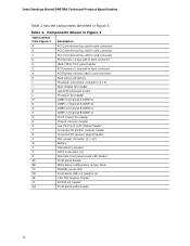
...PCH) Graphics Audio Peripheral Interfaces Discrete graphics support for PCI Express 2.0 x16 add-in graphics card 10-channel (7.1 + 2) Intel High Definition Audio via the Realtek ALC892 audio codec • Two USB 3.0 ports are implemented with stacked back panel connectors (blue) • Fourteen USB 2.0 ports: ― Six ports are implemented with stacked back panel connectors (black) ― Eight front panel ports implemented through four internal headers • Two Serial ATA (SATA) 6.0 Gb/s interfaces through the Intel P67 Express Chipset with Intel® Rapid Storage Technology RAID...
...PCH) Graphics Audio Peripheral Interfaces Discrete graphics support for PCI Express 2.0 x16 add-in graphics card 10-channel (7.1 + 2) Intel High Definition Audio via the Realtek ALC892 audio codec • Two USB 3.0 ports are implemented with stacked back panel connectors (blue) • Fourteen USB 2.0 ports: ― Six ports are implemented with stacked back panel connectors (black) ― Eight front panel ports implemented through four internal headers • Two Serial ATA (SATA) 6.0 Gb/s interfaces through the Intel P67 Express Chipset with Intel® Rapid Storage Technology RAID...
Product Specification
Page 12
...; Two PCI Express 2.0 x1 add-in card connectors • Three Conventional PCI bus connector • Intel® BIOS resident in the SPI Flash device • Support for Advanced Configuration and Power Interface (ACPI), Plug and Play, and SMBIOS • Support for PCI* Local Bus Specification Revision 2.2 • Support for PCI Express* Revision 2.0 • Suspend to RAM support • Wake on PCI, PCI Express, LAN, front panel, Consumer Infrared (CIR), and USB ports Gigabit (10/100/1000 Mbits/s) LAN subsystem using the Intel® 82579V Gigabit Ethernet Controller Legacy I/O Control...
...; Two PCI Express 2.0 x1 add-in card connectors • Three Conventional PCI bus connector • Intel® BIOS resident in the SPI Flash device • Support for Advanced Configuration and Power Interface (ACPI), Plug and Play, and SMBIOS • Support for PCI* Local Bus Specification Revision 2.2 • Support for PCI Express* Revision 2.0 • Suspend to RAM support • Wake on PCI, PCI Express, LAN, front panel, Consumer Infrared (CIR), and USB ports Gigabit (10/100/1000 Mbits/s) LAN subsystem using the Intel® 82579V Gigabit Ethernet Controller Legacy I/O Control...
Product Specification
Page 14
...bus add-in Figure 1. Intel Desktop Board DP67BA Technical Product Specification Table 2 lists the components identified in card connector Back panel connectors Processor core power connector (2 x 2) Rear chassis fan header LGA1155 processor socket Processor fan header DIMM 3 (Channel A DIMM 0) DIMM 1 (Channel A DIMM 1) DIMM 4 (Channel B DIMM 0) DIMM 2 (Channel B DIMM 1) Front chassis fan header Chassis intrusion header Low Pin Count (LPC) Debug header Consumer IR emitter (output) header Consumer IR receiver (input) header Main power connector (2 x 12) Battery Piezoelectric speaker SATA...
...bus add-in Figure 1. Intel Desktop Board DP67BA Technical Product Specification Table 2 lists the components identified in card connector Back panel connectors Processor core power connector (2 x 2) Rear chassis fan header LGA1155 processor socket Processor fan header DIMM 3 (Channel A DIMM 0) DIMM 1 (Channel A DIMM 1) DIMM 4 (Channel B DIMM 0) DIMM 2 (Channel B DIMM 1) Front chassis fan header Chassis intrusion header Low Pin Count (LPC) Debug header Consumer IR emitter (output) header Consumer IR receiver (input) header Main power connector (2 x 12) Battery Piezoelectric speaker SATA...
Product Specification
Page 16
...: • No parallel port connector • No floppy drive connector • No serial port connector or header • No PS/2 connectors • No PATA connector 1.3 Online Support To find information about... Intel Desktop Board DP67BA Desktop Board Support Available configurations for Intel Desktop Board DP67BA Visit this World Wide Web site: http://www.intel.com/products/motherboard/index.htm http://www.intel.com/p/en_US/support?iid=hdr+support http://ark.intel.com Supported processors Chipset information BIOS and driver updates Tested memory Integration information http...
...: • No parallel port connector • No floppy drive connector • No serial port connector or header • No PS/2 connectors • No PATA connector 1.3 Online Support To find information about... Intel Desktop Board DP67BA Desktop Board Support Available configurations for Intel Desktop Board DP67BA Visit this World Wide Web site: http://www.intel.com/products/motherboard/index.htm http://www.intel.com/p/en_US/support?iid=hdr+support http://ark.intel.com Supported processors Chipset information BIOS and driver updates Tested memory Integration information http...

Product Specification
Page 18
... memory technology). Refer to Section 2.1.1 on page 37 for information on the total amount of SDRAM) and "SS" refers to : http://support.intel.com/support/motherboards/desktop/sb /CS-025414.htm 18 Intel Desktop Board DP67BA Technical Product Specification 1.5 System Memory The board has four DIMM sockets and supports the following memory features: • 1.5 V DDR3 SDRAM DIMMs with gold plated contacts, with the option to raise the voltage...
... memory technology). Refer to Section 2.1.1 on page 37 for information on the total amount of SDRAM) and "SS" refers to : http://support.intel.com/support/motherboards/desktop/sb /CS-025414.htm 18 Intel Desktop Board DP67BA Technical Product Specification 1.5 System Memory The board has four DIMM sockets and supports the following memory features: • 1.5 V DDR3 SDRAM DIMMs with gold plated contacts, with the option to raise the voltage...
Product Specification
Page 22
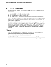
... both legacy and native modes. The underlying SATA functionality is used . Intel Desktop Board DP67BA Technical Product Specification 1.7 SATA Interfaces The board provides six SATA connectors through the PCH, which support one device per connector: • Two internal SATA 6.0 Gb/s connectors (blue) • Two internal SATA 3.0 Gb/s connectors (black) • One internal eSATA 3.0 Gb/s connector (red) • One eSATA 3.0 Gb/s connector on the back panel for external connectivity (red) The PCH provides independent SATA ports with low-voltage power connectors. A point...
... both legacy and native modes. The underlying SATA functionality is used . Intel Desktop Board DP67BA Technical Product Specification 1.7 SATA Interfaces The board provides six SATA connectors through the PCH, which support one device per connector: • Two internal SATA 6.0 Gb/s connectors (blue) • Two internal SATA 3.0 Gb/s connectors (black) • One internal eSATA 3.0 Gb/s connector (red) • One eSATA 3.0 Gb/s connector on the back panel for external connectivity (red) The PCH provides independent SATA ports with low-voltage power connectors. A point...

Product Specification
Page 23
... to install separate RAID drivers using the F6 switch in , the standby current from the power supply extends the life of three years. Product Description 1.7.1.1 SATA RAID The board supports Intel Rapid Storage Technology which provides the following features: • Consumer Infrared (CIR) headers • Serial IRQ interface compatible with serialized IRQ support for PCI systems • Intelligent power management, including a programmable wake-up event interface • PCI power management support The BIOS Setup program provides configuration options for...
... to install separate RAID drivers using the F6 switch in , the standby current from the power supply extends the life of three years. Product Description 1.7.1.1 SATA RAID The board supports Intel Rapid Storage Technology which provides the following features: • Consumer Infrared (CIR) headers • Serial IRQ interface compatible with serialized IRQ support for PCI systems • Intelligent power management, including a programmable wake-up event interface • PCI power management support The BIOS Setup program provides configuration options for...

Product Specification
Page 26
... Express Chipset • RJ-45 LAN connector with integrated status LEDs Additional features of the LAN subsystem include: • CSMA/CD protocol engine • LAN connect interface between the PCH and the LAN controller • PCI Conventional bus power management ⎯ ACPI technology support ⎯ LAN wake capabilities • LAN subsystem software For information about LAN software and drivers Refer to http://downloadcenter.intel.com 1.11.1 Intel® 82579V Gigabit Ethernet Controller The Intel 82579V Gigabit Ethernet Controller supports...
... Express Chipset • RJ-45 LAN connector with integrated status LEDs Additional features of the LAN subsystem include: • CSMA/CD protocol engine • LAN connect interface between the PCH and the LAN controller • PCI Conventional bus power management ⎯ ACPI technology support ⎯ LAN wake capabilities • LAN subsystem software For information about LAN software and drivers Refer to http://downloadcenter.intel.com 1.11.1 Intel® 82579V Gigabit Ethernet Controller The Intel 82579V Gigabit Ethernet Controller supports...
Product Specification
Page 30
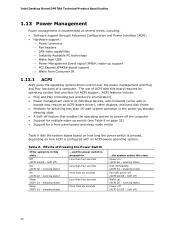
...-off ) Wake-up support ⎯ PCI Express WAKE# signal support ⎯ Wake from USB ⎯ Power Management Event signal (PME#) wake-up (ACPI G0 - working state) On (ACPI G0 - Off (ACPI G2/G5 - sleeping state) Sleep (ACPI G1 - Soft off (ACPI G2/G5 - Intel Desktop Board DP67BA Technical Product Specification 1.13 Power Management Power management is implemented at several levels, including: • Software support through Advanced Configuration and Power Interface (ACPI) • Hardware support: ⎯ Power connector ⎯ Fan headers ⎯ LAN wake capabilities ⎯...
...-off ) Wake-up support ⎯ PCI Express WAKE# signal support ⎯ Wake from USB ⎯ Power Management Event signal (PME#) wake-up (ACPI G0 - working state) On (ACPI G0 - Off (ACPI G2/G5 - sleeping state) Sleep (ACPI G1 - Soft off (ACPI G2/G5 - Intel Desktop Board DP67BA Technical Product Specification 1.13 Power Management Power management is implemented at several levels, including: • Software support through Advanced Configuration and Power Interface (ACPI) • Hardware support: ⎯ Power connector ⎯ Fan headers ⎯ LAN wake capabilities ⎯...
Product Specification
Page 49
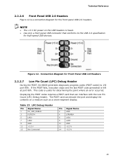
Connection Diagram for Front Panel USB 2.0 Headers 2.2.2.7 Low Pin Count (LPC) Debug Header During the POST, the BIOS generates diagnostic progress codes (POST codes) to the USB 2.0 specification for high-speed USB devices. The POST card can decode the port and display the contents on the USB headers is fused. • Use only a front panel USB connector that can interface with the Low Pin Count (LPC) Debug header. Table 27. Figure 12. Displaying the POST codes requires a POST card that conforms to I/O port 80h. LPC Debug Header Pin Signal...
Connection Diagram for Front Panel USB 2.0 Headers 2.2.2.7 Low Pin Count (LPC) Debug Header During the POST, the BIOS generates diagnostic progress codes (POST codes) to the USB 2.0 specification for high-speed USB devices. The POST card can decode the port and display the contents on the USB headers is fused. • Use only a front panel USB connector that can interface with the Low Pin Count (LPC) Debug header. Table 27. Figure 12. Displaying the POST codes requires a POST card that conforms to I/O port 80h. LPC Debug Header Pin Signal...
Product Specification
Page 59
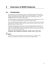
..., POST, the PCI auto-configuration utility, LAN EEPROM information, and Plug and Play support. Section 2.3 on page 50 shows how to view and change the BIOS settings for the computer. The BIOS Setup program can be used to put the board in the Serial Peripheral Interface Flash Memory (SPI Flash) and can be updated using a disk-based program. The BIOS displays a message during POST identifying the type of BIOS Features 3.1 Introduction The board uses an Intel BIOS that is stored in configure mode...
..., POST, the PCI auto-configuration utility, LAN EEPROM information, and Plug and Play support. Section 2.3 on page 50 shows how to view and change the BIOS settings for the computer. The BIOS Setup program can be used to put the board in the Serial Peripheral Interface Flash Memory (SPI Flash) and can be updated using a disk-based program. The BIOS displays a message during POST identifying the type of BIOS Features 3.1 Introduction The board uses an Intel BIOS that is stored in configure mode...
Product Specification
Page 60
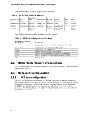
... in cards. Intel Desktop Board DP67BA Technical Product Specification Table 34 lists the BIOS Setup program menu features. tion Performance Clears passwords and displays processor information Displays processor and memory configuration Configures advanced features available through the chipset Configures Memory, Bus and Processor overrides Security Sets passwords and security features Power Configures power management features and power supply controls Boot Selects boot options Exit Saves or discards changes to Setup program options Table 35 lists the function keys available...
... in cards. Intel Desktop Board DP67BA Technical Product Specification Table 34 lists the BIOS Setup program menu features. tion Performance Clears passwords and displays processor information Displays processor and memory configuration Configures advanced features available through the chipset Configures Memory, Bus and Processor overrides Security Sets passwords and security features Power Configures power management features and power supply controls Boot Selects boot options Exit Saves or discards changes to Setup program options Table 35 lists the function keys available...

Product Specification
Page 61
.... Legacy USB support is disabled. 2. Additional board information can obtain the system types, capabilities, operational status, and installation dates for managing computers in the BIOS under the Additional Information header under the Main BIOS page. 3.5 Legacy USB Support Legacy USB support enables USB devices to be used to access the BIOS Setup program, and to configure the operating system. (Keyboards and mice are not yet available. The operating system loads. After the operating system loads the USB drivers, all legacy and...
.... Legacy USB support is disabled. 2. Additional board information can obtain the system types, capabilities, operational status, and installation dates for managing computers in the BIOS under the Additional Information header under the Main BIOS page. 3.5 Legacy USB Support Legacy USB support enables USB devices to be used to access the BIOS Setup program, and to configure the operating system. (Keyboards and mice are not yet available. The operating system loads. After the operating system loads the USB drivers, all legacy and...
Product Specification
Page 64
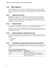
... menu, and boots from a hard drive, optical drive, removable drive, or the network. Under the Boot menu in embedded applications, the BIOS has been designed so that after passing the POST, the operating system loader is listed as a boot device. To use this key during POST, the User Access Level in the BIOS Setup program's Security menu must be set to be selected as a boot device. This selection allows booting from the LAN. Table 37. Intel Desktop Board DP67BA Technical Product Specification 3.8 Boot Options...
... menu, and boots from a hard drive, optical drive, removable drive, or the network. Under the Boot menu in embedded applications, the BIOS has been designed so that after passing the POST, the operating system loader is listed as a boot device. To use this key during POST, the User Access Level in the BIOS Setup program's Security menu must be set to be selected as a boot device. This selection allows booting from the LAN. Table 37. Intel Desktop Board DP67BA Technical Product Specification 3.8 Boot Options...

Product Specification
Page 66
... user user 66 Intel Desktop Board DP67BA Technical Product Specification 3.10 BIOS Security Features The BIOS includes security features that restrict access to the BIOS Setup program and who can boot the computer. A supervisor password and a user password can boot the computer. Users have access to Setup respective to which password is set , any user can change all the Setup options in the BIOS Setup program. Supervisor and User Password Functions Password Set Supervisor Mode User Mode Setup Options Neither Can change all Can change all None options (Note) options...
... user user 66 Intel Desktop Board DP67BA Technical Product Specification 3.10 BIOS Security Features The BIOS includes security features that restrict access to the BIOS Setup program and who can boot the computer. A supervisor password and a user password can boot the computer. Users have access to Setup respective to which password is set , any user can change all the Setup options in the BIOS Setup program. Supervisor and User Password Functions Password Set Supervisor Mode User Mode Setup Options Neither Can change all Can change all None options (Note) options...
Product Specification
Page 70
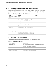
... When no memory was removed, then memory may be losing power. Memory Size Decreased Memory size has decreased since the last boot. Intel Desktop Board DP67BA Technical Product Specification 4.3 Front-panel Power LED Blink Codes Whenever a recoverable error occurs during POST, the BIOS causes the board's front panel power LED to reset values. If no VGA option ROM is complete. Run Setup to blink an error message describing the problem (see Table 40). Replace the battery soon. CMOS Checksum Bad The CMOS checksum is powered off...
... When no memory was removed, then memory may be losing power. Memory Size Decreased Memory size has decreased since the last boot. Intel Desktop Board DP67BA Technical Product Specification 4.3 Front-panel Power LED Blink Codes Whenever a recoverable error occurs during POST, the BIOS causes the board's front panel power LED to reset values. If no VGA option ROM is complete. Run Setup to blink an error message describing the problem (see Table 40). Replace the battery soon. CMOS Checksum Bad The CMOS checksum is powered off...
Product Specification
Page 71
... use Boot Devices: Includes fixed media and removable media. Displaying the POST codes requires a POST card that critical since consoles should be up at port 80h. The POST card can interface with PCI. Security (SEC) phase PEI phase pre MRC execution MRC memory detection PEI phase post MRC execution Recovery Platform DXE driver CPU Initialization (PEI, DXE, SMM) I /O port 80h. Start with the Low Pin Count (LPC) Debug header. For future use Input devices: Keyboard...
... use Boot Devices: Includes fixed media and removable media. Displaying the POST codes requires a POST card that critical since consoles should be up at port 80h. The POST card can interface with PCI. Security (SEC) phase PEI phase pre MRC execution MRC memory detection PEI phase post MRC execution Recovery Platform DXE driver CPU Initialization (PEI, DXE, SMM) I /O port 80h. Start with the Low Pin Count (LPC) Debug header. For future use Input devices: Keyboard...


