
Product Specification
Page 6
...3.5 Legacy USB Support 63 3.6 BIOS Updates 64 3.6.1 Language Support 64 3.6.2 Custom Splash Screen 65 3.7 BIOS Recovery 65 3.8 Boot Options 66 3.8.1 Optical Drive Boot 66 3.8.2 Network Boot 66 3.8.3 Booting Without Attached Devices 66 3.8.4 Changing the Default Boot Device During POST 66 3.9 Adjusting Boot Speed 67 3.9.1 Peripheral Selection and Configuration 67 3.9.2 BIOS Boot Optimizations 67 3.10 BIOS Security Features 68 3.11 BIOS Performance Features 69 4 Error Messages and Beep Codes 4.1 Speaker 71 4.2 BIOS Beep Codes 71 4.3 Front-panel Power LED Blink Codes 72 4.4 BIOS...
...3.5 Legacy USB Support 63 3.6 BIOS Updates 64 3.6.1 Language Support 64 3.6.2 Custom Splash Screen 65 3.7 BIOS Recovery 65 3.8 Boot Options 66 3.8.1 Optical Drive Boot 66 3.8.2 Network Boot 66 3.8.3 Booting Without Attached Devices 66 3.8.4 Changing the Default Boot Device During POST 66 3.9 Adjusting Boot Speed 67 3.9.1 Peripheral Selection and Configuration 67 3.9.2 BIOS Boot Optimizations 67 3.10 BIOS Security Features 68 3.11 BIOS Performance Features 69 4 Error Messages and Beep Codes 4.1 Speaker 71 4.2 BIOS Beep Codes 71 4.3 Front-panel Power LED Blink Codes 72 4.4 BIOS...

Product Specification
Page 7
... 8. Supported Memory Configurations 16 107H 287H 4. Effects of the Onboard Power and Reset Buttons 37 96H 276H 9. SATA Connectors 45 18H 298H 15. S/PDIF Header 45 19H 29H 16. Memory Channel and DIMM Configuration 18 91H 271H 4. Diagnostic LEDs 36 13H 293H 10. Location of Pressing the Power Switch 29 10H 290H 7. Localized High Temperature Zones 58 104H 284H Tables 1. LAN Connector LED Locations 25 93H 273H 6. Board Dimensions 54 103H 283H 16. Connection Diagram for...
... 8. Supported Memory Configurations 16 107H 287H 4. Effects of the Onboard Power and Reset Buttons 37 96H 276H 9. SATA Connectors 45 18H 298H 15. S/PDIF Header 45 19H 29H 16. Memory Channel and DIMM Configuration 18 91H 271H 4. Diagnostic LEDs 36 13H 293H 10. Location of Pressing the Power Switch 29 10H 290H 7. Localized High Temperature Zones 58 104H 284H Tables 1. LAN Connector LED Locations 25 93H 273H 6. Board Dimensions 54 103H 283H 16. Connection Diagram for...

Product Specification
Page 8
.... BIOS Error Messages 72 36. Recommended Power Supply Current Values 55 25. Front-panel Power LED Blink Codes 72 35. EMC Regulations 83 32H 41. BIOS Setup Configuration Jumper Settings 53 24. AcceptableDrives/Media Types for a Two-Color Power LED 50 23. BIOS Beep Codes 71 34. Front Panel Header 49 21. Port 80h POST Code Ranges 73 37. States for BIOS Recovery 65 31. Fan Header Current Capability 56 26. Safety Standards 79 40. Processor Core Power Connector 48 19. Boot Device Menu Options 66...
.... BIOS Error Messages 72 36. Recommended Power Supply Current Values 55 25. Front-panel Power LED Blink Codes 72 35. EMC Regulations 83 32H 41. BIOS Setup Configuration Jumper Settings 53 24. AcceptableDrives/Media Types for a Two-Color Power LED 50 23. BIOS Beep Codes 71 34. Front Panel Header 49 21. Port 80h POST Code Ranges 73 37. States for BIOS Recovery 65 31. Fan Header Current Capability 56 26. Safety Standards 79 40. Processor Core Power Connector 48 19. Boot Device Menu Options 66...

Product Specification
Page 9
...; High Definition Audio subsystem using the Realtek* ALC892 audio codec Legacy I/O Control Peripheral Interfaces Wireless Module BIOS Nuvoton* legacy I/O controller for Consumer Infrared (CIR) • Two USB 3.0 ports are implemented with stacked back panel connectors (blue) • Fourteen USB 2.0 ports: ― Eight ports are implemented with stacked back panel connectors (black) ― Six front panel ports implemented through three internal headers • Two Serial ATA (SATA) 6.0 Gb/s interfaces through the Intel P67 Express Chipset with Intel® Rapid Storage Technology RAID...
...; High Definition Audio subsystem using the Realtek* ALC892 audio codec Legacy I/O Control Peripheral Interfaces Wireless Module BIOS Nuvoton* legacy I/O controller for Consumer Infrared (CIR) • Two USB 3.0 ports are implemented with stacked back panel connectors (blue) • Fourteen USB 2.0 ports: ― Eight ports are implemented with stacked back panel connectors (black) ― Six front panel ports implemented through three internal headers • Two Serial ATA (SATA) 6.0 Gb/s interfaces through the Intel P67 Express Chipset with Intel® Rapid Storage Technology RAID...

Product Specification
Page 12
... Express x1 bus add-in card connector B Conventional PCI bus add-in card connector J Back panel connectors K 12 V processor core voltage connector (2 x 4 pin) L LGA1155 processor socket M Processor fan header N DIMM 3 (Channel A DIMM 0) O DIMM 1 (Channel A DIMM 1) P DIMM 4 (Channel B DIMM 0) Q DIMM 2 (Channel B DIMM 1) R Alternate front panel power LED header S Main power connector (2 x 12 pin) T POST code LED display U Onboard power button V Onboard reset button W Speaker X Front chassis fan header Y Battery Z Intel P67 Express Chipset AA SATA connectors...
... Express x1 bus add-in card connector B Conventional PCI bus add-in card connector J Back panel connectors K 12 V processor core voltage connector (2 x 4 pin) L LGA1155 processor socket M Processor fan header N DIMM 3 (Channel A DIMM 0) O DIMM 1 (Channel A DIMM 1) P DIMM 4 (Channel B DIMM 0) Q DIMM 2 (Channel B DIMM 1) R Alternate front panel power LED header S Main power connector (2 x 12 pin) T POST code LED display U Onboard power button V Onboard reset button W Speaker X Front chassis fan header Y Battery Z Intel P67 Express Chipset AA SATA connectors...

Product Specification
Page 14
... parallel port connector • No floppy drive connector • No PS/2 connectors 1.3 Online Support To find information about ... Supported processors Refer to: http://processormatch.intel.com CAUTION Use only the processors listed on power supply requirements for this World Wide Web site: http://www.intel.com/products/motherboard/index.htm http://www.intel.com/p/en_US/support?iid=hdr+support http://ark.intel.com Supported processors Chipset information BIOS and driver updates Tested memory Integration information http://processormatch.intel.com...
... parallel port connector • No floppy drive connector • No PS/2 connectors 1.3 Online Support To find information about ... Supported processors Refer to: http://processormatch.intel.com CAUTION Use only the processors listed on power supply requirements for this World Wide Web site: http://www.intel.com/products/motherboard/index.htm http://www.intel.com/p/en_US/support?iid=hdr+support http://ark.intel.com Supported processors Chipset information BIOS and driver updates Tested memory Integration information http://processormatch.intel.com...

Product Specification
Page 15
... memory speeds above 1600 MHz NOTE To be fully compliant with DIMMs that support the Serial Presence Detect (SPD) data structure. Refer to accurately configure memory settings for an aggregate of addressable memory. • Minimum total system memory: 1 GB using 4 Gb memory technology). Product Description 1.4.1 PCI Express x16 Graphics The Intel Core i7, Intel Core i5, and Intel Core i3 processors in an LGA1155 socket support discrete add in graphics cards via the PCI Express 2.0 x16 graphics connector: • Supports PCI Express GEN2 frequency...
... memory speeds above 1600 MHz NOTE To be fully compliant with DIMMs that support the Serial Presence Detect (SPD) data structure. Refer to accurately configure memory settings for an aggregate of addressable memory. • Minimum total system memory: 1 GB using 4 Gb memory technology). Product Description 1.4.1 PCI Express x16 Graphics The Intel Core i7, Intel Core i5, and Intel Core i3 processors in an LGA1155 socket support discrete add in graphics cards via the PCI Express 2.0 x16 graphics connector: • Supports PCI Express GEN2 frequency...
Product Specification
Page 19
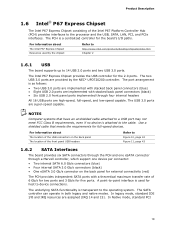
...://www.intel.com/products/desktop/chipsets/index.htm Chapter 2 1.6.1 USB The board supports up to 14 USB 2.0 ports and two USB 3.0 ports. In legacy mode, standard IDE I /O paths. The Intel P67 Express Chipset provides the USB controller for full-speed devices. In Native mode, standard PCI 19 The underlying SATA functionality is transparent to the cable. The SATA controller can operate in both legacy and native modes. For information about The location of the USB connectors on the back panel for external connectivity...
...://www.intel.com/products/desktop/chipsets/index.htm Chapter 2 1.6.1 USB The board supports up to 14 USB 2.0 ports and two USB 3.0 ports. In legacy mode, standard IDE I /O paths. The Intel P67 Express Chipset provides the USB controller for full-speed devices. In Native mode, standard PCI 19 The underlying SATA functionality is transparent to the cable. The SATA controller can operate in both legacy and native modes. For information about The location of the USB connectors on the back panel for external connectivity...

Product Specification
Page 20
... RAID drivers. Intel Desktop Board DP67BG Technical Product Specification Conventional bus resource steering is only supported when using the Windows* XP, Windows Vista*, and Windows 7* operating systems. NOTE Many SATA drives use supported RAID features, you must first enable RAID in the operating system installation process. 20 NOTE In order to install separate RAID drivers using the F6 switch in the BIOS. See your Microsoft Windows XP documentation for both AHCI and RAID without the need to use new low-voltage power connectors...
... RAID drivers. Intel Desktop Board DP67BG Technical Product Specification Conventional bus resource steering is only supported when using the Windows* XP, Windows Vista*, and Windows 7* operating systems. NOTE Many SATA drives use supported RAID features, you must first enable RAID in the operating system installation process. 20 NOTE In order to install separate RAID drivers using the F6 switch in the BIOS. See your Microsoft Windows XP documentation for both AHCI and RAID without the need to use new low-voltage power connectors...

Product Specification
Page 21
Product Description 1.7 Real-Time Clock Subsystem A coin-cell battery (CR2032) powers the real-time clock and CMOS memory. When the voltage drops below a certain level, the BIOS Setup program settings stored in CMOS RAM (for the I/O controller. 1.8.1 Consumer Infrared (CIR) The Consumer Infrared (CIR) feature is made up event interface • PCI power management support The BIOS Setup program provides configuration options for example, the date and time) might not be...
Product Description 1.7 Real-Time Clock Subsystem A coin-cell battery (CR2032) powers the real-time clock and CMOS memory. When the voltage drops below a certain level, the BIOS Setup program settings stored in CMOS RAM (for the I/O controller. 1.8.1 Consumer Infrared (CIR) The Consumer Infrared (CIR) feature is made up event interface • PCI power management support The BIOS Setup program provides configuration options for example, the date and time) might not be...

Product Specification
Page 24
... Specification 1.10 LAN Subsystem The LAN subsystem consists of the following: • Intel 82579V Gigabit Ethernet Controller (10/100/1000 Mbits/s) • Intel P67 Express Chipset • RJ-45 LAN connector with integrated status LEDs Additional features of the LAN subsystem include: • CSMA/CD protocol engine • LAN connect interface between the PCH and the LAN controller • Conventional PCI bus power management ⎯ ACPI technology support ⎯ LAN wake capabilities • LAN subsystem software...
... Specification 1.10 LAN Subsystem The LAN subsystem consists of the following: • Intel 82579V Gigabit Ethernet Controller (10/100/1000 Mbits/s) • Intel P67 Express Chipset • RJ-45 LAN connector with integrated status LEDs Additional features of the LAN subsystem include: • CSMA/CD protocol engine • LAN connect interface between the PCH and the LAN controller • Conventional PCI bus power management ⎯ ACPI technology support ⎯ LAN wake capabilities • LAN subsystem software...

Product Specification
Page 29
...) Wake-up support ⎯ PCI Express WAKE# signal support ⎯ Wake from USB ⎯ Power Management Event signal (PME#) wake-up (ACPI G0 - working state) Soft-off (ACPI G2/G5 - Off (ACPI G2/G5 - Table 6. sleeping state) ...and the power switch is pressed for a front panel power and sleep mode switch Table 6 lists the system states based on how long the power switch is pressed, depending on how ACPI is configured with this board requires an operating system that enables...
...) Wake-up support ⎯ PCI Express WAKE# signal support ⎯ Wake from USB ⎯ Power Management Event signal (PME#) wake-up (ACPI G0 - working state) Soft-off (ACPI G2/G5 - Off (ACPI G2/G5 - Table 6. sleeping state) ...and the power switch is pressed for a front panel power and sleep mode switch Table 6 lists the system states based on how long the power switch is pressed, depending on how ACPI is configured with this board requires an operating system that enables...

Product Specification
Page 51
Connection Diagram for high-speed USB devices. Figure 13. NOTE • The +5 V DC power on the USB headers is a connection diagram for the front panel USB headers. Technical Reference 2.2.2.5 Front Panel USB Headers Figure 13 is fused. • Use only a front panel USB connector that conforms to the USB 2.0 specification for Front Panel USB Headers 51
Connection Diagram for high-speed USB devices. Figure 13. NOTE • The +5 V DC power on the USB headers is a connection diagram for the front panel USB headers. Technical Reference 2.2.2.5 Front Panel USB Headers Figure 13 is fused. • Use only a front panel USB connector that conforms to the USB 2.0 specification for Front Panel USB Headers 51

Product Specification
Page 61
... configure mode. 61 The menu bar is accessed by pressing the key after the Power-On Self-Test (POST) memory test begins and before the operating system boot begins. The BIOS displays a message during POST identifying the type of BIOS Features 3.1 Introduction The board uses an Intel BIOS that is set to view and change the BIOS settings for the computer. The SPI Flash contains the BIOS Setup program, POST, the PCI auto-configuration utility, LAN EEPROM information, and Plug and Play support...
... configure mode. 61 The menu bar is accessed by pressing the key after the Power-On Self-Test (POST) memory test begins and before the operating system boot begins. The BIOS displays a message during POST identifying the type of BIOS Features 3.1 Introduction The board uses an Intel BIOS that is set to view and change the BIOS settings for the computer. The SPI Flash contains the BIOS Setup program, POST, the PCI auto-configuration utility, LAN EEPROM information, and Plug and Play support...

Product Specification
Page 62
Table 29. BIOS Setup Program Menu Bar Maintenance Main Configura- tion Performance Security Power Clears passwords and displays processor information Displays processor and memory configuration Configures advanced features available through the chipset Configures Memory, Bus and Processor overrides Sets passwords and security features Configures power management features and power supply controls Boot Selects boot options Exit Saves or discards changes to Setup program options Table 29 lists the function keys available for the current menu Save the current values ...
Table 29. BIOS Setup Program Menu Bar Maintenance Main Configura- tion Performance Security Power Clears passwords and displays processor information Displays processor and memory configuration Configures advanced features available through the chipset Configures Memory, Bus and Processor overrides Sets passwords and security features Configures power management features and power supply controls Boot Selects boot options Exit Saves or discards changes to Setup program options Table 29 lists the function keys available for the current menu Save the current values ...

Product Specification
Page 66
...in card with a remote boot ROM installed. Table 31. Boot Device Menu Options Boot Device Menu Function Keys or Description Selects a default boot device Exits the menu, saves changes, and boots from the LAN. Intel Desktop Board DP67BG Technical Product Specification 3.8 Boot Options In the BIOS Setup program, the user can be displayed. Under the Boot menu in the BIOS Setup program, the optical drive is supported in the BIOS setup program's Boot Device Priority Submenu). Pressing the key during POST causes a boot device menu to be the first boot device, the hard drive second...
...in card with a remote boot ROM installed. Table 31. Boot Device Menu Options Boot Device Menu Function Keys or Description Selects a default boot device Exits the menu, saves changes, and boots from the LAN. Intel Desktop Board DP67BG Technical Product Specification 3.8 Boot Options In the BIOS Setup program, the user can be displayed. Under the Boot menu in the BIOS Setup program, the optical drive is supported in the BIOS setup program's Boot Device Priority Submenu). Pressing the key during POST causes a boot device menu to be the first boot device, the hard drive second...
Product Specification
Page 67
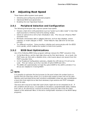
... four seconds of option ROM boot time. • The BIOS will automatically not load the option ROM for the SATA controller if no drives are installed in the Drive Configuration Submenu of the BIOS Setup program). 67 This rate can influence POST execution time. • Eliminate unnecessary add-in adapter features, such as logo displays, screen repaints, or mode changes in less than eight seconds to minimize hard drive startup delays. •...
... four seconds of option ROM boot time. • The BIOS will automatically not load the option ROM for the SATA controller if no drives are installed in the Drive Configuration Submenu of the BIOS Setup program). 67 This rate can influence POST execution time. • Eliminate unnecessary add-in adapter features, such as logo displays, screen repaints, or mode changes in less than eight seconds to minimize hard drive startup delays. •...

Product Specification
Page 68
... change all Setup options. Passwords may be displayed before the computer is set , the user can enter either the supervisor password or the user password to access Setup. The password prompt will be up to 16 characters in the BIOS Setup program. Password to Enter Setup None Password During Boot None Supervisor None User User Supervisor or Supervisor or user user 68 This table is for a password. This is not displayed on the screen. Intel Desktop Board DP67BG Technical Product Specification 3.10 BIOS...
... change all Setup options. Passwords may be displayed before the computer is set , the user can enter either the supervisor password or the user password to access Setup. The password prompt will be up to 16 characters in the BIOS Setup program. Password to Enter Setup None Password During Boot None Supervisor None User User Supervisor or Supervisor or user user 68 This table is for a password. This is not displayed on the screen. Intel Desktop Board DP67BG Technical Product Specification 3.10 BIOS...

Product Specification
Page 72
... for 0.5 seconds. CMOS memory may be bad. If no VGA option ROM is found. 4.4 BIOS Error Messages Table 35 lists the error messages and provides a brief description of 16 blinks. Intel Desktop Board DP67BG Technical Product Specification 4.3 Front-panel Power LED Blink Codes Whenever a recoverable error occurs during POST, the BIOS causes the board's front panel power LED to boot. 72 Front-panel Power LED Blink Codes Type Pattern F2 Setup/F10 Boot Menu None Prompt BIOS update in a total of each. Video error Memory error On-off (1.0 second...
... for 0.5 seconds. CMOS memory may be bad. If no VGA option ROM is found. 4.4 BIOS Error Messages Table 35 lists the error messages and provides a brief description of 16 blinks. Intel Desktop Board DP67BG Technical Product Specification 4.3 Front-panel Power LED Blink Codes Whenever a recoverable error occurs during POST, the BIOS causes the board's front panel power LED to boot. 72 Front-panel Power LED Blink Codes Type Pattern F2 Setup/F10 Boot Menu None Prompt BIOS update in a total of each. Video error Memory error On-off (1.0 second...

Product Specification
Page 73
... Recovery 0x36 - 0x3F Platform DXE driver 0x41 - 0x4F CPU Initialization (PEI, DXE, SMM) 0x50 - 0x5F 0x60 - 0x6F I /O port 80h. Port 80h POST Code Ranges Range Subsystem 0x00 - 0x05 Entering SX states S0 to I /O Buses: PCI, USB, ATA etc. 0x5F is an unrecoverable error. Not that critical since consoles should be installed in PCI bus connector 1. Error Messages and Beep Codes 4.5 Port 80h POST Codes During the POST, the BIOS generates diagnostic progress codes (POST codes) to...
... Recovery 0x36 - 0x3F Platform DXE driver 0x41 - 0x4F CPU Initialization (PEI, DXE, SMM) 0x50 - 0x5F 0x60 - 0x6F I /O port 80h. Port 80h POST Code Ranges Range Subsystem 0x00 - 0x05 Entering SX states S0 to I /O Buses: PCI, USB, ATA etc. 0x5F is an unrecoverable error. Not that critical since consoles should be installed in PCI bus connector 1. Error Messages and Beep Codes 4.5 Port 80h POST Codes During the POST, the BIOS generates diagnostic progress codes (POST codes) to...


