
Product Specification
Page 5
...9 1.1.1 Feature Summary 9 1.1.2 Board Layout 11 1.1.3 Block Diagram 13 1.2 Legacy Considerations 14 1.3 Online Support 14 1.4 Processor 14 1.5 System Memory 15 1.5.1 Memory Configurations 17 1.6 Intel® P67 Express Chipset 19 1.6.1 PCI Express x16 Graphics 19 1.6.2 USB 19 1.6.3 SATA Interfaces 19 1.7 Real-Time Clock... 21 1.9 Audio Subsystem 22 1.9.1 Audio Subsystem Software 22 1.9.2 Audio Subsystem Components 22 1.10 LAN Subsystem 24 1.10.1 Intel® 82579V Gigabit Ethernet Controller 24 1.10.2 LAN Subsystem Software 25 1.10.3 RJ-45 LAN Connector with Integrated LEDs 25...
...9 1.1.1 Feature Summary 9 1.1.2 Board Layout 11 1.1.3 Block Diagram 13 1.2 Legacy Considerations 14 1.3 Online Support 14 1.4 Processor 14 1.5 System Memory 15 1.5.1 Memory Configurations 17 1.6 Intel® P67 Express Chipset 19 1.6.1 PCI Express x16 Graphics 19 1.6.2 USB 19 1.6.3 SATA Interfaces 19 1.7 Real-Time Clock... 21 1.9 Audio Subsystem 22 1.9.1 Audio Subsystem Software 22 1.9.2 Audio Subsystem Components 22 1.10 LAN Subsystem 24 1.10.1 Intel® 82579V Gigabit Ethernet Controller 24 1.10.2 LAN Subsystem Software 25 1.10.3 RJ-45 LAN Connector with Integrated LEDs 25...

Product Specification
Page 8
...Menu Bar 62 29. Supervisor and User Password Functions 68 33. BIOS Error Messages 72 36. Regulatory Compliance Marks 87 14H 324H viii Processor, Front and Rear Chassis, and Auxiliary (4-Pin) Fan Headers ..... 46 18. Front Panel Header 49 21. States for Components 58 27... Port 80h POST Code Ranges 73 37. Safety Standards 79 40. Intel Desktop Board DP67BG Technical Product Specification 17. Thermal Considerations for a Two-Color Power LED 50 23. EMC Regulations 83 32H 41. Processor Core Power Connector 48 19. States for BIOS Recovery 65 31. ...
...Menu Bar 62 29. Supervisor and User Password Functions 68 33. BIOS Error Messages 72 36. Regulatory Compliance Marks 87 14H 324H viii Processor, Front and Rear Chassis, and Auxiliary (4-Pin) Fan Headers ..... 46 18. Front Panel Header 49 21. States for Components 58 27... Port 80h POST Code Ranges 73 37. Safety Standards 79 40. Intel Desktop Board DP67BG Technical Product Specification 17. Thermal Considerations for a Two-Color Power LED 50 23. EMC Regulations 83 32H 41. Processor Core Power Connector 48 19. States for BIOS Recovery 65 31. ...

Product Specification
Page 9
...for non-ECC memory • Support for 1.35 V low voltage JEDEC memory • Support for XMP memory Intel® P67 Express Chipset consisting of the board. Feature Summary Form Factor Processor Memory Chipset Audio ATX (12.00 inches by 9.60 inches [304.80 millimeters by 243.84 millimeters]) •...; Intel® Core™ i7, Intel® Core™ i5, and Intel® Core™ i3 processors with up to 95 W TDP in an LGA1155 socket: ― 1 x16 PCIe 2.0 Graphics interface (operates ...
...for non-ECC memory • Support for 1.35 V low voltage JEDEC memory • Support for XMP memory Intel® P67 Express Chipset consisting of the board. Feature Summary Form Factor Processor Memory Chipset Audio ATX (12.00 inches by 9.60 inches [304.80 millimeters by 243.84 millimeters]) •...; Intel® Core™ i7, Intel® Core™ i5, and Intel® Core™ i3 processors with up to 95 W TDP in an LGA1155 socket: ― 1 x16 PCIe 2.0 Graphics interface (operates ...

Product Specification
Page 12
... PCI bus add-in card connector J Back panel connectors K 12 V processor core voltage connector (2 x 4 pin) L LGA1155 processor socket M Processor fan header N DIMM 3 (Channel A DIMM 0) O DIMM 1 (...Channel A DIMM 1) P DIMM 4 (Channel B DIMM 0) Q DIMM 2 (Channel B DIMM 1) R Alternate front panel power LED header S Main power connector (2 x 12 pin) T POST code LED display U Onboard power button V Onboard reset button W Speaker X Front chassis fan header Y Battery Z Intel...
... PCI bus add-in card connector J Back panel connectors K 12 V processor core voltage connector (2 x 4 pin) L LGA1155 processor socket M Processor fan header N DIMM 3 (Channel A DIMM 0) O DIMM 1 (...Channel A DIMM 1) P DIMM 4 (Channel B DIMM 0) Q DIMM 2 (Channel B DIMM 1) R Alternate front panel power LED header S Main power connector (2 x 12 pin) T POST code LED display U Onboard power button V Onboard reset button W Speaker X Front chassis fan header Y Battery Z Intel...

Product Specification
Page 14
... up-to-date list of supported processors. Supported processors Refer to: http://processormatch.intel.com CAUTION Use only the processors listed on power supply requirements for greater than 150 W operation. This board is designed to support the Intel Core i7, Intel Core i5, and Intel Core i3 processors in an LGA1155 socket Other processors may be supported in the...
... up-to-date list of supported processors. Supported processors Refer to: http://processormatch.intel.com CAUTION Use only the processors listed on power supply requirements for greater than 150 W operation. This board is designed to support the Intel Core i7, Intel Core i5, and Intel Core i3 processors in an LGA1155 socket Other processors may be supported in the...

Product Specification
Page 15
... DDR3 1066 MHz SDRAM DIMMs • XMP version 1.2 performance profile support for optimum performance. Product Description 1.4.1 PCI Express x16 Graphics The Intel Core i7, Intel Core i5, and Intel Core i3 processors in an LGA1155 socket support discrete add in graphics cards via the PCI Express 2.0 x16 graphics connector: • Supports PCI Express GEN2...
... DDR3 1066 MHz SDRAM DIMMs • XMP version 1.2 performance profile support for optimum performance. Product Description 1.4.1 PCI Express x16 Graphics The Intel Core i7, Intel Core i5, and Intel Core i3 processors in an LGA1155 socket support discrete add in graphics cards via the PCI Express 2.0 x16 graphics connector: • Supports PCI Express GEN2...

Product Specification
Page 17
... other but the installed memory capacity for real world applications. Technology and device width can vary from one channel to : http://www.intel.com/support/motherboards/desktop/sb/cs011965.htm 17 Dual channel mode is enabled when the installed memory capacities of memory organization: • Dual... slowest memory timing will be used. This mode is used . • Single channel (Asymmetric) mode. Product Description 1.5.1 Memory Configurations The Intel Core i7, Intel Core i5, and Intel Core i3 processors support the following types of both DIMM channels are unequal.
... other but the installed memory capacity for real world applications. Technology and device width can vary from one channel to : http://www.intel.com/support/motherboards/desktop/sb/cs011965.htm 17 Dual channel mode is enabled when the installed memory capacities of memory organization: • Dual... slowest memory timing will be used. This mode is used . • Single channel (Asymmetric) mode. Product Description 1.5.1 Memory Configurations The Intel Core i7, Intel Core i5, and Intel Core i3 processors support the following types of both DIMM channels are unequal.
Product Specification
Page 18
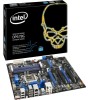
Memory Channel and DIMM Configuration NOTE The Intel Core i7, Intel Core i5, and Intel Core i3 processors require memory to be populated in your configuration. 18 Figure 3. Intel Desktop Board DP67BG Technical Product Specification Figure 3 illustrates the memory channel and DIMM configuration. For best memory performance always install memory into the blue DIMM memory sockets if only installing two DIMMs in the DIMM 1 (Channel A, DIMM 0) socket.
Memory Channel and DIMM Configuration NOTE The Intel Core i7, Intel Core i5, and Intel Core i3 processors require memory to be populated in your configuration. 18 Figure 3. Intel Desktop Board DP67BG Technical Product Specification Figure 3 illustrates the memory channel and DIMM configuration. For best memory performance always install memory into the blue DIMM memory sockets if only installing two DIMMs in the DIMM 1 (Channel A, DIMM 0) socket.
Product Specification
Page 19
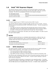
... Express Chipset provides the USB controller for full-speed devices. The USB 3.0 ports are provided by the chipset Refer to http://www.intel.com/products/desktop/chipsets/index.htm Chapter 2 1.6.1 USB The board supports up to the cable. In legacy mode, standard IDE I /O paths. .... In Native mode, standard PCI 19 The port arrangement is a centralized controller for host to the processor and the USB, SATA, LAN, PCI, and PCIe interfaces. For information about The Intel P67 Express Chipset Resources used for the board's I /O and IRQ resources are implemented with stacked back...
... Express Chipset provides the USB controller for full-speed devices. The USB 3.0 ports are provided by the chipset Refer to http://www.intel.com/products/desktop/chipsets/index.htm Chapter 2 1.6.1 USB The board supports up to the cable. In legacy mode, standard IDE I /O paths. .... In Native mode, standard PCI 19 The port arrangement is a centralized controller for host to the processor and the USB, SATA, LAN, PCI, and PCIe interfaces. For information about The Intel P67 Express Chipset Resources used for the board's I /O and IRQ resources are implemented with stacked back...

Product Specification
Page 27
... enable the board to the chassis intrusion header. The board has several hardware management features, including the following : • Processor and system ambient temperature monitoring • Chassis fan speed monitoring • Power monitoring of the chassis intrusion header Refer to Section... 1.13.2.2, page 33 1.12.3 Chassis Intrusion and Detection The board supports a chassis security feature that attaches to be implemented using Intel® Desktop Control Center or third-party software. For information about The location of +12 V, +5 V, +3.3 V, V_SM and +VCCP ...
... enable the board to the chassis intrusion header. The board has several hardware management features, including the following : • Processor and system ambient temperature monitoring • Chassis fan speed monitoring • Power monitoring of the chassis intrusion header Refer to Section... 1.13.2.2, page 33 1.12.3 Chassis Intrusion and Detection The board supports a chassis security feature that attaches to be implemented using Intel® Desktop Control Center or third-party software. For information about The location of +12 V, +5 V, +3.3 V, V_SM and +VCCP ...

Product Specification
Page 28
Intel Desktop Board DP67BG Technical Product Specification 1.12.4 Thermal Monitoring Figure 6 shows the locations of the thermal sensors and fan headers. Item A B C D E F G Description Rear chassis fan header Voltage regulator thermal diode Thermal diode, located on processor die Processor fan header Front chassis fan header Thermal diode, located on the Intel P67 Express Chipset Auxiliary fan header Figure 6. Thermal Sensors and Fan Headers 28
Intel Desktop Board DP67BG Technical Product Specification 1.12.4 Thermal Monitoring Figure 6 shows the locations of the thermal sensors and fan headers. Item A B C D E F G Description Rear chassis fan header Voltage regulator thermal diode Thermal diode, located on processor die Processor fan header Front chassis fan header Thermal diode, located on the Intel P67 Express Chipset Auxiliary fan header Figure 6. Thermal Sensors and Fan Headers 28

Product Specification
Page 30
...and knowledge of how devices are not being used can be turned off . S5 - C0 - No power D3 - Notes: 1. Intel Desktop Board DP67BG Technical Product Specification 1.13.1.1 System States and Power States Under ACPI, the operating system directs all system and device ...transitions. Table 7 lists the power states supported by the system chassis' power supply. 2. Power States and Targeted System Power Global States Sleeping States Processor States Device States Targeted System Power (Note 1) G0 - working state G1 - Suspend to disk. Context saved to RAM. D3 - D3 ...
...and knowledge of how devices are not being used can be turned off . S5 - C0 - No power D3 - Notes: 1. Intel Desktop Board DP67BG Technical Product Specification 1.13.1.1 System States and Power States Under ACPI, the operating system directs all system and device ...transitions. Table 7 lists the power states supported by the system chassis' power supply. 2. Power States and Targeted System Power Global States Sleeping States Processor States Device States Targeted System Power (Note 1) G0 - working state G1 - Suspend to disk. Context saved to RAM. D3 - D3 ...
Product Specification
Page 36
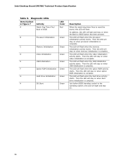
... is complete. Diagnostic LEDs Item/Callout in Figure 7 Activity A Watch Dog Timer Fire/ Back to BIOS LED Color Red B Processor Initialization Green C Memory Initialization Green D Video Initialization Green E USB Initialization Green F Option ROM Initialization Green G Hard Drive Initialization... LED will stay on . 36 This LED will flash when the processor initialization activity starts. Then the LED will light and stay on when video initialization is complete. Intel Desktop Board DP67BG Technical Product Specification Table 9. This LED will flash ...
... is complete. Diagnostic LEDs Item/Callout in Figure 7 Activity A Watch Dog Timer Fire/ Back to BIOS LED Color Red B Processor Initialization Green C Memory Initialization Green D Video Initialization Green E USB Initialization Green F Option ROM Initialization Green G Hard Drive Initialization... LED will stay on . 36 This LED will flash when the processor initialization activity starts. Then the LED will light and stay on when video initialization is complete. Intel Desktop Board DP67BG Technical Product Specification Table 9. This LED will flash ...
Product Specification
Page 44
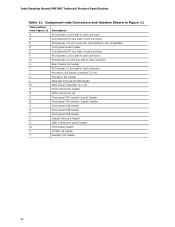
... 11 Item/callout from Figure 11 A B C D E F G H I J K L M N Description PCI Express x1 bus add-in card connector Conventional PCI bus add-in card connector Processor core power connector (2 X 4) Processor fan header Alternate front panel LED header Main power connector (2 x 12) Front chassis fan header O SATA connectors (6) P Front panel CIR receiver (input) header Q Front...2.0 x16 bus add-in card connector Rear chassis fan header PCI Express x1 bus add-in card connector PCI Express 2.0 x16 connector (x8 electrical; Intel Desktop Board DP67BG Technical Product Specification Table 11.
... 11 Item/callout from Figure 11 A B C D E F G H I J K L M N Description PCI Express x1 bus add-in card connector Conventional PCI bus add-in card connector Processor core power connector (2 X 4) Processor fan header Alternate front panel LED header Main power connector (2 x 12) Front chassis fan header O SATA connectors (6) P Front panel CIR receiver (input) header Q Front...2.0 x16 bus add-in card connector Rear chassis fan header PCI Express x1 bus add-in card connector PCI Express 2.0 x16 connector (x8 electrical; Intel Desktop Board DP67BG Technical Product Specification Table 11.
Product Specification
Page 46
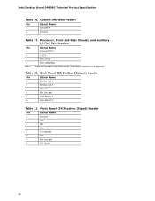
... Signal Name 1 Ground 2 LED 3 NC 4 Learn-in 5 5 V standby 6 VCC 7 Key (no pin) 5 Jack detect 1 6 Jack detect 2 Table 21. Processor, Front and Rear Chassis, and Auxiliary (4-Pin) Fan Headers Pin Signal Name 1 Ground (Note) 2 +12 V 3 FAN_TACH 4 FAN_CONTROL Note: These fan headers use Pulse Width...(Output) Header Pin Signal Name 1 Emitter out 1 2 Emitter out 2 3 Ground 4 Key (no pin) 8 CIR Input 46 Intel Desktop Board DP67BG Technical Product Specification Table 16. Chassis Intrusion Header Pin Signal Name 1 Intruder# 2 Ground Table 17.
... Signal Name 1 Ground 2 LED 3 NC 4 Learn-in 5 5 V standby 6 VCC 7 Key (no pin) 5 Jack detect 1 6 Jack detect 2 Table 21. Processor, Front and Rear Chassis, and Auxiliary (4-Pin) Fan Headers Pin Signal Name 1 Ground (Note) 2 +12 V 3 FAN_TACH 4 FAN_CONTROL Note: These fan headers use Pulse Width...(Output) Header Pin Signal Name 1 Emitter out 1 2 Emitter out 2 3 Ground 4 Key (no pin) 8 CIR Input 46 Intel Desktop Board DP67BG Technical Product Specification Table 16. Chassis Intrusion Header Pin Signal Name 1 Intruder# 2 Ground Table 17.

Product Specification
Page 48
...Pin Signal Name 13 +3.3 V 2 +3.3 V 14 -12 V 3 Ground 4 +5 V 5 Ground 6 +5 V 15 Ground 16 PS-ON# (power supply remote on Intel Desktop boards. This connector provides power directly to Section 2.5.1 on the rightmost pins of ATX12V power supplies with either 2 x 10 or 2 x 12 main power cables... power - a 2 x 12 connector. The board supports the use of the main power connector, leaving pins 11, 12, 23, and 24 unconnected. • Processor core power - Failure to do so will be used on /off) 17 Ground 18 Ground 7 Ground 8 PWRGD (Power Good) 9 +5 V (Standby) 10...
...Pin Signal Name 13 +3.3 V 2 +3.3 V 14 -12 V 3 Ground 4 +5 V 5 Ground 6 +5 V 15 Ground 16 PS-ON# (power supply remote on Intel Desktop boards. This connector provides power directly to Section 2.5.1 on the rightmost pins of ATX12V power supplies with either 2 x 10 or 2 x 12 main power cables... power - a 2 x 12 connector. The board supports the use of the main power connector, leaving pins 11, 12, 23, and 24 unconnected. • Processor core power - Failure to do so will be used on /off) 17 Ground 18 Ground 7 Ground 8 PWRGD (Power Good) 9 +5 V (Standby) 10...

Product Specification
Page 52
... location of the Jumper Block 52 When the jumper is set to configure mode and the computer is powered-up, the BIOS compares the processor version and the microcode version in the BIOS and reports if the two match. The 3-pin jumper block determines the BIOS Setup program's .... Otherwise, the board could be damaged. Figure 14. Table 23 describes the jumper settings for the three modes: normal, configure, and recovery. Intel Desktop Board DP67BG Technical Product Specification 2.3 Jumper Block CAUTION Do not move the jumper with the power on. Always turn off the power and unplug...
... location of the Jumper Block 52 When the jumper is set to configure mode and the computer is powered-up, the BIOS compares the processor version and the microcode version in the BIOS and reports if the two match. The 3-pin jumper block determines the BIOS Setup program's .... Otherwise, the board could be damaged. Figure 14. Table 23 describes the jumper settings for the three modes: normal, configure, and recovery. Intel Desktop Board DP67BG Technical Product Specification 2.3 Jumper Block CAUTION Do not move the jumper with the power on. Always turn off the power and unplug...
Product Specification
Page 55
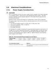
...8226; All voltage tolerances For example, for a system consisting of a supported 95 W processor (see Section 1.4 on page 14 for a list of providing adequate +5 V standby current. Failure to http://support.intel.com/support/motherboards/desktop/sb /CS-026472.htm 55 Table 24 lists the recommended power supply... supply. Additional power required will depend on the wake devices supported and manufacturing options. The power supply must be capable of supported processors), 4 GB DDR3 RAM, one high end video card, one hard disk drive, one optical drive, and all board peripherals enabled...
...8226; All voltage tolerances For example, for a system consisting of a supported 95 W processor (see Section 1.4 on page 14 for a list of providing adequate +5 V standby current. Failure to http://support.intel.com/support/motherboards/desktop/sb /CS-026472.htm 55 Table 24 lists the recommended power supply... supply. Additional power required will depend on the wake devices supported and manufacturing options. The power supply must be capable of supported processors), 4 GB DDR3 RAM, one high end video card, one hard disk drive, one optical drive, and all board peripherals enabled...
Product Specification
Page 56
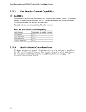
...a chassis fan header may result in onboard component damage that will halt fan operation. Fan Header Current Capability Fan Header Maximum Available Current Processor fan Front chassis fan Rear chassis fan Auxiliary chassis fan 1.5 A 1.5 A 1.5 A 1.5 A 2.5.3 Add-in Board Considerations The board... boards for each add-in board from the +5 V rail. Connecting the processor fan to a chassis fan header. Intel Desktop Board DP67BG Technical Product Specification 2.5.2 Fan Header Current Capability CAUTION The processor fan must not exceed the system's power supply +5 V maximum current or 14...
...a chassis fan header may result in onboard component damage that will halt fan operation. Fan Header Current Capability Fan Header Maximum Available Current Processor fan Front chassis fan Rear chassis fan Auxiliary chassis fan 1.5 A 1.5 A 1.5 A 1.5 A 2.5.3 Add-in Board Considerations The board... boards for each add-in board from the +5 V rail. Connecting the processor fan to a chassis fan header. Intel Desktop Board DP67BG Technical Product Specification 2.5.2 Fan Header Current Capability CAUTION The processor fan must not exceed the system's power supply +5 V maximum current or 14...
Product Specification
Page 57
... maintained in an open chassis. 57 Intel makes no warranties or representations that have been tested with Intel desktop boards please refer to the following the instructions presented in this document will result in damage to the processor voltage regulator area. CAUTION Ensure that... so could cause components to maintain required airflow across the processor voltage regulator area. Failure to 85 oC in the processor voltage regulator circuit. For a list of chassis that merely following website: http://www3.intel.com/cd/channel/reseller/asmo-na/eng/tech_reference/53211.htm All...
... maintained in an open chassis. 57 Intel makes no warranties or representations that have been tested with Intel desktop boards please refer to the following the instructions presented in this document will result in damage to the processor voltage regulator area. CAUTION Ensure that... so could cause components to maintain required airflow across the processor voltage regulator area. Failure to 85 oC in the processor voltage regulator circuit. For a list of chassis that merely following website: http://www3.intel.com/cd/channel/reseller/asmo-na/eng/tech_reference/53211.htm All...


