
Product Specification
Page 5
Contents 1 Product Description 1.1 Overview 10 1.1.1 Feature Summary 10 1.1.2 Board Layout 12 1.1.3 Block Diagram 14 1.2 Legacy Considerations 15 1.3 Online Support 15 1.4 Processor 15 1.5 System Memory 16 1.5.1 Memory Configurations 17 1.6 Intel® X48 Chipset 19 1.6.1 USB 19 1.6.2 Serial ATA Interfaces 20 1.7 Discrete eSATA/PATA Controller 21 1.7.1 External Serial ATA Support 21 1.7.2 Parallel ATA IDE Controller...
Contents 1 Product Description 1.1 Overview 10 1.1.1 Feature Summary 10 1.1.2 Board Layout 12 1.1.3 Block Diagram 14 1.2 Legacy Considerations 15 1.3 Online Support 15 1.4 Processor 15 1.5 System Memory 16 1.5.1 Memory Configurations 17 1.6 Intel® X48 Chipset 19 1.6.1 USB 19 1.6.2 Serial ATA Interfaces 20 1.7 Discrete eSATA/PATA Controller 21 1.7.1 External Serial ATA Support 21 1.7.2 Parallel ATA IDE Controller...
Product Specification
Page 7
... and Headers 45 12. Connection Diagram for Front Panel USB Headers 54 14. Wake-up Devices and Events 34 8. Front Panel Audio Header 47 12. Processor and Rear Chassis 2 (4-Pin) Fan Headers 48 16. Memory Channel and DIMM Configuration 18 4. LAN Connector LED Locations 27 6. Connection Diagram for IEEE 1394a Header...
... and Headers 45 12. Connection Diagram for Front Panel USB Headers 54 14. Wake-up Devices and Events 34 8. Front Panel Audio Header 47 12. Processor and Rear Chassis 2 (4-Pin) Fan Headers 48 16. Memory Channel and DIMM Configuration 18 4. LAN Connector LED Locations 27 6. Connection Diagram for IEEE 1394a Header...

Product Specification
Page 8
Boot Device Menu Options 69 32. Intel Desktop Board DX48BT2 Technical Product Specification 17. Front Panel Header 52 21. BIOS Setup Configuration Jumper Settings 55 24. BIOS Setup Program Menu Bar 64 ... Keys 64 30. Product Certification Markings 86 viii Auxiliary PCI Express Graphics Power 51 20. Beep Codes 73 34. Lead-Free Board Markings 84 40. Processor Core Power Connector 50 18. Recommended Power Supply Current Values 57 25. Port 80h POST Code Ranges 74 36. Port 80h POST Codes 75 37.
Boot Device Menu Options 69 32. Intel Desktop Board DX48BT2 Technical Product Specification 17. Front Panel Header 52 21. BIOS Setup Configuration Jumper Settings 55 24. BIOS Setup Program Menu Bar 64 ... Keys 64 30. Product Certification Markings 86 viii Auxiliary PCI Express Graphics Power 51 20. Beep Codes 73 34. Lead-Free Board Markings 84 40. Processor Core Power Connector 50 18. Recommended Power Supply Current Values 57 25. Port 80h POST Code Ranges 74 36. Port 80h POST Codes 75 37.

Product Specification
Page 9
1 Product Description What This Chapter Contains 1.1 Overview 10 1.2 Legacy Considerations 15 1.3 Online Support 15 1.4 Processor 15 1.5 System Memory 16 1.6 Intel® X48 Chipset 19 1.7 Discrete eSATA/PATA Controller 21 1.8 Real-Time Clock Subsystem 22 1.9 Legacy I/O Controller 23 1.10 Audio Subsystem 24 1.11 LAN Subsystem 26 1.12 Hardware Management Subsystem 29 1.13 Power Management 31 1.14 Onboard Power Button 39 9
1 Product Description What This Chapter Contains 1.1 Overview 10 1.2 Legacy Considerations 15 1.3 Online Support 15 1.4 Processor 15 1.5 System Memory 16 1.6 Intel® X48 Chipset 19 1.7 Discrete eSATA/PATA Controller 21 1.8 Real-Time Clock Subsystem 22 1.9 Legacy I/O Controller 23 1.10 Audio Subsystem 24 1.11 LAN Subsystem 26 1.12 Hardware Management Subsystem 29 1.13 Power Management 31 1.14 Onboard Power Button 39 9

Product Specification
Page 10
....00 inches by 9.60 inches [304.80 millimeters by 243.84 millimeters]) • Intel® Core™2 Extreme Processor in an LGA775 socket with a 1600 MHz, 1333 MHz, and 1066 MHz system bus • Intel® Core™2 Quad Processor in an LGA775 socket with a 1333 MHz and 1066 MHz system bus •...; Intel® Core™2 Duo Processor in an LGA775 socket with a 1333 MHz, 1066 MHz, and 800 MHz system bus ...
....00 inches by 9.60 inches [304.80 millimeters by 243.84 millimeters]) • Intel® Core™2 Extreme Processor in an LGA775 socket with a 1600 MHz, 1333 MHz, and 1066 MHz system bus • Intel® Core™2 Quad Processor in an LGA775 socket with a 1333 MHz and 1066 MHz system bus •...; Intel® Core™2 Duo Processor in an LGA775 socket with a 1333 MHz, 1066 MHz, and 800 MHz system bus ...

Product Specification
Page 13
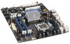
... H Rear chassis fan header I Memory Controller Hub (MCH) fan header J Back panel connectors K Processor core power connector (2 X 4) L LGA775 processor socket M Processor fan header N DIMM Channel A sockets [2] O DIMM Channel B sockets [2] P Parallel ATE IDE connector Q Main power connector R Front chassis fan header S Intel 82X48 Memory Controller Hub (MCH) T Chassis intrusion header U Battery V Serial ATA connectors [6] W Front...
... H Rear chassis fan header I Memory Controller Hub (MCH) fan header J Back panel connectors K Processor core power connector (2 X 4) L LGA775 processor socket M Processor fan header N DIMM Channel A sockets [2] O DIMM Channel B sockets [2] P Parallel ATE IDE connector Q Main power connector R Front chassis fan header S Intel 82X48 Memory Controller Hub (MCH) T Chassis intrusion header U Battery V Serial ATA connectors [6] W Front...

Product Specification
Page 15
.../support/motherboards/desktop/DX48BT2 http://www.intel.com/products/motherboard/DX48BT2/index.htm http://www.intel.com/go/findcpu http://www.intel.com/products/desktop/chipsets/index.htm http://downloadcenter.intel.com/Product_Filter.aspx?ProductID=2912 1.4 Processor The board is designed to support the following processors: • Intel Core 2 Extreme Processor in an LGA775 socket with a 1600 MHz...
.../support/motherboards/desktop/DX48BT2 http://www.intel.com/products/motherboard/DX48BT2/index.htm http://www.intel.com/go/findcpu http://www.intel.com/products/desktop/chipsets/index.htm http://downloadcenter.intel.com/Product_Filter.aspx?ProductID=2912 1.4 Processor The board is designed to support the following processors: • Intel Core 2 Extreme Processor in an LGA775 socket with a 1600 MHz...

Product Specification
Page 16
.... 16 This allows the BIOS to read the SPD data and program the chipset to the processor. Intel Desktop Board DX48BT2 Technical Product Specification CAUTION Use only the processors listed on the XMP format. It is recommended that support the Serial Presence Detect (SPD) data... system memory for optimum performance. Refer to Section 2.1.1 on page 41 for information on the total amount of unsupported processors can damage the board, the processor, and the power supply. # INTEGRATOR'S NOTE This board has specific requirements for providing power to accurately configure memory settings...
.... 16 This allows the BIOS to read the SPD data and program the chipset to the processor. Intel Desktop Board DX48BT2 Technical Product Specification CAUTION Use only the processors listed on the XMP format. It is recommended that support the Serial Presence Detect (SPD) data... system memory for optimum performance. Refer to Section 2.1.1 on page 41 for information on the total amount of unsupported processors can damage the board, the processor, and the power supply. # INTEGRATOR'S NOTE This board has specific requirements for providing power to accurately configure memory settings...
Product Specification
Page 19
... UHCI- For information about The location of the USB connectors on the back panel The location of the following devices: • Intel 82X48 Memory Controller Hub (MCH) with dual stacked back panel connectors adjacent to the audio connectors • Four ports are implemented ...provides the USB controller for the board's I /O Controller Hub (ICH9R) The MCH component provides interfaces to the processor, memory, and PCI Express. Product Description 1.6 Intel® X48 Chipset The Intel X48 chipset consists of the front panel USB headers Refer to Figure 10, page 44 Figure 11, page 45...
... UHCI- For information about The location of the USB connectors on the back panel The location of the following devices: • Intel 82X48 Memory Controller Hub (MCH) with dual stacked back panel connectors adjacent to the audio connectors • Four ports are implemented ...provides the USB controller for the board's I /O Controller Hub (ICH9R) The MCH component provides interfaces to the processor, memory, and PCI Express. Product Description 1.6 Intel® X48 Chipset The Intel X48 chipset consists of the front panel USB headers Refer to Figure 10, page 44 Figure 11, page 45...

Product Specification
Page 21
... the six SATA connectors of 3 Gbits/sec per port. The discrete SATA interface supports the following modes: • Programmed I/O (PIO): processor controls data transfer. • 8237-style DMA: DMA offloads the processor, supporting transfer rates of up to 16 MB/sec. • Ultra DMA: DMA protocol on IDE bus supporting host and...
... the six SATA connectors of 3 Gbits/sec per port. The discrete SATA interface supports the following modes: • Programmed I/O (PIO): processor controls data transfer. • 8237-style DMA: DMA offloads the processor, supporting transfer rates of up to 16 MB/sec. • Ultra DMA: DMA protocol on IDE bus supporting host and...
Product Specification
Page 28
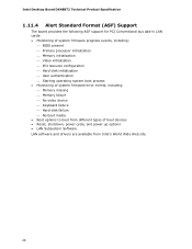
Intel Desktop Board DX48BT2 Technical Product Specification 1.11.4 Alert Standard Format (ASF) Support The board provides the following ASF support for PCI Conventional bus add-in LAN cards: • Monitoring of system firmware progress events, including: ⎯ BIOS present ⎯ Primary processor initialization ⎯ Memory initialization ⎯ Video initialization ⎯ PCI resource ...different types of boot devices • Reset, shutdown, power cycle, and power up options • LAN Subsystem Software LAN software and drivers are available from Intel's World Wide Web site. 28
Intel Desktop Board DX48BT2 Technical Product Specification 1.11.4 Alert Standard Format (ASF) Support The board provides the following ASF support for PCI Conventional bus add-in LAN cards: • Monitoring of system firmware progress events, including: ⎯ BIOS present ⎯ Primary processor initialization ⎯ Memory initialization ⎯ Video initialization ⎯ PCI resource ...different types of boot devices • Reset, shutdown, power cycle, and power up options • LAN Subsystem Software LAN software and drivers are available from Intel's World Wide Web site. 28
Product Specification
Page 29
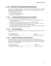
When the chassis cover is removed, the mechanical switch is in the processor, 82X48 MCH, and 82801IR ICH9R • Power supply monitoring of the fan headers Refer to Section 1.13.2.2, page 36 1.12.3 Chassis Intrusion and Detection The ... that detects if the chassis cover is removed. Product Description 1.12 Hardware Management Subsystem The hardware management features enable the board to be implemented using Intel® Desktop Control Center or third-party software.
When the chassis cover is removed, the mechanical switch is in the processor, 82X48 MCH, and 82801IR ICH9R • Power supply monitoring of the fan headers Refer to Section 1.13.2.2, page 36 1.12.3 Chassis Intrusion and Detection The ... that detects if the chassis cover is removed. Product Description 1.12 Hardware Management Subsystem The hardware management features enable the board to be implemented using Intel® Desktop Control Center or third-party software.
Product Specification
Page 30
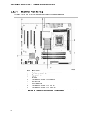
Item A B C D E F G H Description Auxiliary rear chassis fan Rear chassis fan MCH fan Thermal diode, located on processor die Processor fan Front chassis fan Thermal diode, located on the MCH die Thermal diode, located on the ICH9R die Figure 6. Intel Desktop Board DX48BT2 Technical Product Specification 1.12.4 Thermal Monitoring Figure 6 shows the locations of the thermal sensors and fan headers. Thermal Sensors and Fan Headers 30
Item A B C D E F G H Description Auxiliary rear chassis fan Rear chassis fan MCH fan Thermal diode, located on processor die Processor fan Front chassis fan Thermal diode, located on the MCH die Thermal diode, located on the ICH9R die Figure 6. Intel Desktop Board DX48BT2 Technical Product Specification 1.12.4 Thermal Monitoring Figure 6 shows the locations of the thermal sensors and fan headers. Thermal Sensors and Fan Headers 30

Product Specification
Page 33
... - S5 - Suspend to RAM. Notes: 1. Context saved to the system. Power States and Targeted System Power Global States Sleeping States Processor States Device States Targeted System Power (Note 1) G0 - working D0 - Product Description Table 6 lists the power states supported by the system...up logic. 5 W < power < 52.5 W Power < 5 W (Note 2) Power < 5 W (Note 2) Power < 5 W (Note 2) G3 - Full power > 30 W G1 - Processor stopped C1 - Context not saved. No power No power No power D1, D2, D3 - No power to disk. Dependent on the system configuration, including add...
... - S5 - Suspend to RAM. Notes: 1. Context saved to the system. Power States and Targeted System Power Global States Sleeping States Processor States Device States Targeted System Power (Note 1) G0 - working D0 - Product Description Table 6 lists the power states supported by the system...up logic. 5 W < power < 52.5 W Power < 5 W (Note 2) Power < 5 W (Note 2) Power < 5 W (Note 2) G3 - Full power > 30 W G1 - Processor stopped C1 - Context not saved. No power No power No power D1, D2, D3 - No power to disk. Dependent on the system configuration, including add...

Product Specification
Page 38
...contains two LEDs that indicate the following: • The Processor LED indicates an elevated temperature on the board. Failure to do so could effect performance Figure 7 shows the location of Indicator LEDs 38 Intel Desktop Board DX48BT2 Technical Product Specification 1.13.2.8 +5 V ...devices. Figure 7 shows the location of the standby power indicator LED on the processor that could effect performance • The Voltage Regulator LED indicates an elevated temperature in the processor voltage regulator circuit that could damage the board and any devices connected to the ...
...contains two LEDs that indicate the following: • The Processor LED indicates an elevated temperature on the board. Failure to do so could effect performance Figure 7 shows the location of Indicator LEDs 38 Intel Desktop Board DX48BT2 Technical Product Specification 1.13.2.8 +5 V ...devices. Figure 7 shows the location of the standby power indicator LED on the processor that could effect performance • The Voltage Regulator LED indicates an elevated temperature in the processor voltage regulator circuit that could damage the board and any devices connected to the ...

Product Specification
Page 46
...G Primary PCI Express x16 (electrical x16) bus add-in card connector H Rear chassis fan header I Memory Controller Hub (MCH) fan header J Processor core power connector (2 X 4) K Processor fan header L Parallel ATA IDE connector M Main power connector N Front chassis fan header O Chassis intrusion header P Serial ATA connectors [6] Q Front...CIR emitter (output) header W Front panel header X High Definition Audio Link header Y Auxiliary PCI Express graphics power connector Z S/PDIF connector 46 Intel Desktop Board DX48BT2 Technical Product Specification Table 9.
...G Primary PCI Express x16 (electrical x16) bus add-in card connector H Rear chassis fan header I Memory Controller Hub (MCH) fan header J Processor core power connector (2 X 4) K Processor fan header L Parallel ATA IDE connector M Main power connector N Front chassis fan header O Chassis intrusion header P Serial ATA connectors [6] Q Front...CIR emitter (output) header W Front panel header X High Definition Audio Link header Y Auxiliary PCI Express graphics power connector Z S/PDIF connector 46 Intel Desktop Board DX48BT2 Technical Product Specification Table 9.
Product Specification
Page 48
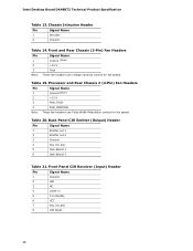
... Front Panel CIR Receiver (Input) Header Pin Signal Name 1 Ground 2 LED 3 NC 4 Learn-in 5 5 V standby 6 VCC 7 Key (no pin) 5 Jack detect 1 6 Jack detect 2 Table 21. Processor and Rear Chassis 2 (4-Pin) Fan Headers Pin 1 2 3 Signal Name Ground (Note) +12 V FAN_TACH 4 FAN_CONTROL Note: These fan headers use voltage variance control for fan speed...
... Front Panel CIR Receiver (Input) Header Pin Signal Name 1 Ground 2 LED 3 NC 4 Learn-in 5 5 V standby 6 VCC 7 Key (no pin) 5 Jack detect 1 6 Jack detect 2 Table 21. Processor and Rear Chassis 2 (4-Pin) Fan Headers Pin 1 2 3 Signal Name Ground (Note) +12 V FAN_TACH 4 FAN_CONTROL Note: These fan headers use voltage variance control for fan speed...
Product Specification
Page 50
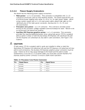
... PCI Express graphics power connector to the board and the add-in cards. Failure to do so may cause damage to ensure stable board operation. Processor Core Power Connector Pin Signal Name Pin Signal Name 1 Ground 2 +12 V 3 Ground 4 +12 V 5 Ground 6 +12 V 7 Ground 8 ...17. This connector provides power directly to do so will prevent the board from booting. • Auxiliary PCI Express graphics power - Intel Desktop Board DX48BT2 Technical Product Specification 2.2.2.4 Power Supply Connectors The board has the following power supply connectors: • Main power -...
... PCI Express graphics power connector to the board and the add-in cards. Failure to do so may cause damage to ensure stable board operation. Processor Core Power Connector Pin Signal Name Pin Signal Name 1 Ground 2 +12 V 3 Ground 4 +12 V 5 Ground 6 +12 V 7 Ground 8 ...17. This connector provides power directly to do so will prevent the board from booting. • Auxiliary PCI Express graphics power - Intel Desktop Board DX48BT2 Technical Product Specification 2.2.2.4 Power Supply Connectors The board has the following power supply connectors: • Main power -...

Product Specification
Page 55
... recover the BIOS configuration. Figure 15 shows the location of the Jumper Block Table 23. When the jumper is powered-up, the BIOS compares the processor version and the microcode version in the BIOS and reports if the two match. Location of the jumper block. Always turn off the power and...
... recover the BIOS configuration. Figure 15 shows the location of the Jumper Block Table 23. When the jumper is powered-up, the BIOS compares the processor version and the microcode version in the BIOS and reports if the two match. Location of the jumper block. Always turn off the power and...
Product Specification
Page 57
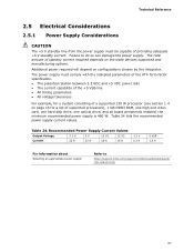
... • All timing parameters • All voltage tolerances For example, for a system consisting of a supported 130 W processor (see section 1.4 on page 15 for a list of supported processors), 1 GB DDR3 RAM, one high end video card, one hard disk drive, one optical drive, and all board ...peripherals enabled, the minimum recommended power supply is 460 W. The total amount of providing adequate +5 V standby current. Failure to http://support.intel.com/support/...
... • All timing parameters • All voltage tolerances For example, for a system consisting of a supported 130 W processor (see section 1.4 on page 15 for a list of supported processors), 1 GB DDR3 RAM, one high end video card, one hard disk drive, one optical drive, and all board ...peripherals enabled, the minimum recommended power supply is 460 W. The total amount of providing adequate +5 V standby current. Failure to http://support.intel.com/support/...


