
Product Guide
Page 5
Contents 1 Desktop Board Features Supported Operating Systems 11 Desktop Board Components 12 Processor ...14 System Memory 15 Memory Configurations 16 Intel® X79 Express Chipset 17 USB Support ...17 USB 3.0 ...17 USB 2.0 ...17 Serial ATA...17 Audio Subsystem 18 LAN Subsystem 18 Legacy I/O ...19 Expandability...19 ...
Contents 1 Desktop Board Features Supported Operating Systems 11 Desktop Board Components 12 Processor ...14 System Memory 15 Memory Configurations 16 Intel® X79 Express Chipset 17 USB Support ...17 USB 3.0 ...17 USB 2.0 ...17 Serial ATA...17 Audio Subsystem 18 LAN Subsystem 18 Legacy I/O ...19 Expandability...19 ...

Product Guide
Page 6
Intel Desktop Board DX79TO Product Guide 2 Installing and Replacing Desktop Board Components Before You Begin 31 Installation Precautions 32 Prevent Power Supply Overload 32 Observe Safety and Regulatory Requirements 32 Installing the I/O Shield 33 Installing the Desktop Board 34 Installing a Processor 35 Installing a Processor Fan Heat Sink 39 ... BIOS Configuration Jumper 54 Clearing Passwords 55 Replacing the Battery 56 3 Updating the BIOS Updating the BIOS with the Intel® Express BIOS Update Utility 63 Updating the BIOS Using the F7 Function Key 64 Updating the BIOS with the...
Intel Desktop Board DX79TO Product Guide 2 Installing and Replacing Desktop Board Components Before You Begin 31 Installation Precautions 32 Prevent Power Supply Overload 32 Observe Safety and Regulatory Requirements 32 Installing the I/O Shield 33 Installing the Desktop Board 34 Installing a Processor 35 Installing a Processor Fan Heat Sink 39 ... BIOS Configuration Jumper 54 Clearing Passwords 55 Replacing the Battery 56 3 Updating the BIOS Updating the BIOS with the Intel® Express BIOS Update Utility 63 Updating the BIOS Using the F7 Function Key 64 Updating the BIOS with the...

Product Guide
Page 7
Memory Channel and DIMM Configuration 16 3. Intel Desktop Board DX79TO Mounting Screw Hole Locations 34 10. Install the Processor 37 13. Installing a DIMM 41 16. POST Code LED Display 71 27. Location of Communications Compliance Statement 82 Japan VCCI Statement 82... Department of the Diagnostic/Status LEDs 27 8. Installing Linked PCI Express Graphics Cards 45 19. Location of the Back to the Processor Fan Header 39 15. Intel Desktop Board DX79TO Components 12 2. Location of the Chassis Fan Headers 52 23. Onboard System Control Switches 26 7. Unlatch the ...
Memory Channel and DIMM Configuration 16 3. Intel Desktop Board DX79TO Mounting Screw Hole Locations 34 10. Install the Processor 37 13. Installing a DIMM 41 16. POST Code LED Display 71 27. Location of Communications Compliance Statement 82 Japan VCCI Statement 82... Department of the Diagnostic/Status LEDs 27 8. Installing Linked PCI Express Graphics Cards 45 19. Location of the Back to the Processor Fan Header 39 15. Intel Desktop Board DX79TO Components 12 2. Location of the Chassis Fan Headers 52 23. Onboard System Control Switches 26 7. Unlatch the ...

Product Guide
Page 9
... Board Features This chapter briefly describes the features of the Intel® X79 Platform Controller Hub (PCH) Graphics Audio Expansion Capabilities Legacy I /O Controller that provides Consumer Infrared (CIR) support continued 9 Feature Summary Form Factor Processor Main Memory Chipset ATX (304.80 millimeters [12.00... inches] x 243.84 millimeters [9.60 inches]) Support for Intel® Core™ i7 and Intel® Xeon® processors in the LGA2011 package with: • Two PCI Express* 3.0 x16 graphics interfaces (x16 electrical) •...
... Board Features This chapter briefly describes the features of the Intel® X79 Platform Controller Hub (PCH) Graphics Audio Expansion Capabilities Legacy I /O Controller that provides Consumer Infrared (CIR) support continued 9 Feature Summary Form Factor Processor Main Memory Chipset ATX (304.80 millimeters [12.00... inches] x 243.84 millimeters [9.60 inches]) Support for Intel® Core™ i7 and Intel® Xeon® processors in the LGA2011 package with: • Two PCI Express* 3.0 x16 graphics interfaces (x16 electrical) •...

Product Guide
Page 10
...― One port routed to the back panel ― One port routed to an IEEE 1394a header • Six Serial ATA (SATA) channels through the Intel X79 PCH: LAN Support BIOS ― Two onboard 6.0 Gb/s SATA channels (blue connectors) ― Four onboard 3.0 Gb/s SATA channels (black connectors) ...PWM control • Four fan sense inputs used to monitor fan activity • Fan speed control using voltage control (4-pin fan headers for processor, front, rear, and auxiliary fans) with selectable support in the BIOS for 3-wire fans • Support for the Platform Environmental Control Interface ...
...― One port routed to the back panel ― One port routed to an IEEE 1394a header • Six Serial ATA (SATA) channels through the Intel X79 PCH: LAN Support BIOS ― Two onboard 6.0 Gb/s SATA channels (blue connectors) ― Four onboard 3.0 Gb/s SATA channels (black connectors) ...PWM control • Four fan sense inputs used to monitor fan activity • Fan speed control using voltage control (4-pin fan headers for processor, front, rear, and auxiliary fans) with selectable support in the BIOS for 3-wire fans • Support for the Platform Environmental Control Interface ...

Product Guide
Page 14
... to the following page or link for more information on installing or upgrading the processor, page 35 in Chapter 2 • Supported processors for Intel Desktop Board DX79TO • Supported processors http://ark.intel.com http://processormatch.intel.com • Chipset information http://www.intel.com/products/desktop/chipsets/index.htm • BIOS and driver updates http://downloadcenter...
... to the following page or link for more information on installing or upgrading the processor, page 35 in Chapter 2 • Supported processors for Intel Desktop Board DX79TO • Supported processors http://ark.intel.com http://processormatch.intel.com • Chipset information http://www.intel.com/products/desktop/chipsets/index.htm • BIOS and driver updates http://downloadcenter...

Product Guide
Page 15
...for normal operation. The operating system may (i) reduce system stability and the useful life of 1 GB • Up to http://www.intel.com/support/processors/sb/CS-020033.htm?wapkw=(processor+warranty). The other damage; If your memory modules do not support SPD, you will attempt to a maximum of 4 GB of the... processor beyond its specifications. Intel has not tested and does not warranty the operation of memory. For information on the desktop board, if used by add-in the ...
...for normal operation. The operating system may (i) reduce system stability and the useful life of 1 GB • Up to http://www.intel.com/support/processors/sb/CS-020033.htm?wapkw=(processor+warranty). The other damage; If your memory modules do not support SPD, you will attempt to a maximum of 4 GB of the... processor beyond its specifications. Intel has not tested and does not warranty the operation of memory. For information on the desktop board, if used by add-in the ...

Product Guide
Page 16
... DX79TO Product Guide Memory Configurations The Intel Core i7 and Intel Xeon processors support the following types of both DIMM channels are equal. Dual-channel mode is installed or the channel memory capacities are used when only a single ...
... DX79TO Product Guide Memory Configurations The Intel Core i7 and Intel Xeon processors support the following types of both DIMM channels are equal. Dual-channel mode is installed or the channel memory capacities are used when only a single ...
Product Guide
Page 17
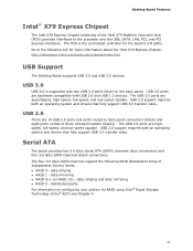
... for RAID using Intel® Rapid Storage Technology (Intel® RST) see Chapter 4. 17 Desktop Board Features Intel® X79 Express Chipset The Intel X79 Express Chipset consisting of Independent Drives) levels: • RAID 0 - data striping • RAID 1 - Go to the processor and the USB,...ports are backward compatible with two USB 3.0 ports (blue) on configuring your system for more information about the Intel X79 Express Chipset: http://developer.intel.com/products/chipsets/index.htm USB Support The Desktop Board supports USB 3.0 and USB 2.0 devices. distributed parity ...
... for RAID using Intel® Rapid Storage Technology (Intel® RST) see Chapter 4. 17 Desktop Board Features Intel® X79 Express Chipset The Intel X79 Express Chipset consisting of Independent Drives) levels: • RAID 0 - data striping • RAID 1 - Go to the processor and the USB,...ports are backward compatible with two USB 3.0 ports (blue) on configuring your system for more information about the Intel X79 Express Chipset: http://developer.intel.com/products/chipsets/index.htm USB Support The Desktop Board supports USB 3.0 and USB 2.0 devices. distributed parity ...

Product Guide
Page 19
...management, including a programmable wake up and the LAN subsystem is powered up event interface • PCI power management support Expandability Intel Desktop Board DX79TO provides the following expansion capability: • Two PCI Express 3.0 x16 connectors. These LEDs indicate the status ...of the LAN. Figure 3. Operation at PCI Express 3.0 speeds requires a processor that provides the following legacy I /O controller that supports the PCI Express 3.0 Specification. • Three PCI Express 2.0 x1 connectors &#...
...management, including a programmable wake up and the LAN subsystem is powered up event interface • PCI power management support Expandability Intel Desktop Board DX79TO provides the following expansion capability: • Two PCI Express 3.0 x16 connectors. These LEDs indicate the status ...of the LAN. Figure 3. Operation at PCI Express 3.0 speeds requires a processor that provides the following legacy I /O controller that supports the PCI Express 3.0 Specification. • Three PCI Express 2.0 x1 connectors &#...

Product Guide
Page 21
Location of the Back to BIOS Button Hardware Management The hardware management features of Intel Desktop Board DX79TO enable the board to be compatible with the following exceptions: • It can only be used to invoke BIOS recovery mode. ... to the factory defaults, use the key once BIOS setup mode is activated. The board has several hardware management features including the following : • Processor and system ambient temperature monitoring • Monitoring of power supply voltages to detect levels above and below acceptable values • Chassis fan speed monitoring •...
Location of the Back to BIOS Button Hardware Management The hardware management features of Intel Desktop Board DX79TO enable the board to be compatible with the following exceptions: • It can only be used to invoke BIOS recovery mode. ... to the factory defaults, use the key once BIOS setup mode is activated. The board has several hardware management features including the following : • Processor and system ambient temperature monitoring • Monitoring of power supply voltages to detect levels above and below acceptable values • Chassis fan speed monitoring •...

Product Guide
Page 23
... and control device. • All fan headers support closed-loop fan control that powers up of the computer through a network. The Desktop Board has a 4-pin processor fan header and three 4-pin chassis fan headers. Failure to provide adequate standby current when using this Desktop Board must be used with this feature...
... and control device. • All fan headers support closed-loop fan control that powers up of the computer through a network. The Desktop Board has a 4-pin processor fan header and three 4-pin chassis fan headers. Failure to provide adequate standby current when using this Desktop Board must be used with this feature...

Product Guide
Page 28
... will flash. Then the LED will light and stay on when the Back to BIOS button has been pressed. Intel Desktop Board DX79TO Product Guide System Initialization LEDs At initial power on when video initialization is complete. System Initialization LEDs... Activity Watch Dog Timer Fire/ Back to BIOS Item/Callout in Figure 7 K LED Color Red Processor Initialization G Memory Initialization F Video Initialization E USB Initialization C Mass Storage B Initialization Option ROM D Initialization OS Start A Green Green ...
... will flash. Then the LED will light and stay on when the Back to BIOS button has been pressed. Intel Desktop Board DX79TO Product Guide System Initialization LEDs At initial power on when video initialization is complete. System Initialization LEDs... Activity Watch Dog Timer Fire/ Back to BIOS Item/Callout in Figure 7 K LED Color Red Processor Initialization G Memory Initialization F Video Initialization E USB Initialization C Mass Storage B Initialization Option ROM D Initialization OS Start A Green Green ...
Product Guide
Page 29
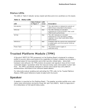
Table 5. Trusted Platform Module (TPM) A Nuvoton* WPCT210 TPM component on the processor that could affect board performance. The TPM is designed to the board. Indicates that could affect board performance. Refer to Appendix A for a ...and other security critical tasks. For information about enabling and activating the TPM, refer to operate. Status LEDs LED Item/Callout LED in the processor voltage regulator circuit that the system has experienced a catastrophic error and cannot continue to the Trusted Platform Module (TPM) Quick Reference Guide included with...
Table 5. Trusted Platform Module (TPM) A Nuvoton* WPCT210 TPM component on the processor that could affect board performance. The TPM is designed to the board. Indicates that could affect board performance. Refer to Appendix A for a ...and other security critical tasks. For information about enabling and activating the TPM, refer to operate. Status LEDs LED Item/Callout LED in the processor voltage regulator circuit that the system has experienced a catastrophic error and cannot continue to the Trusted Platform Module (TPM) Quick Reference Guide included with...
Product Guide
Page 31
... chassis. 31 2 Installing and Replacing Desktop Board Components This chapter tells you how to: • Install the I/O shield • Install the Desktop Board • Install a processor • Install memory • Install and remove a PCI Express x16 card • Connect the Serial ATA cables • Connect to the internal headers and connectors...
... chassis. 31 2 Installing and Replacing Desktop Board Components This chapter tells you how to: • Install the I/O shield • Install the Desktop Board • Install a processor • Install memory • Install and remove a PCI Express x16 card • Connect the Serial ATA cables • Connect to the internal headers and connectors...

Product Guide
Page 32
...connectors • Sharp pins on printed circuit assemblies • Rough edges and sharp corners on the chassis • Hot components (such as processors, voltage regulators, and heat sinks) • Damage to wires that could cause a short circuit Observe all warnings and cautions that instruct you...or the instructions for associated modules, contact the supplier to find out how you to refer computer servicing to Appendix B. 32 Intel Desktop Board DX79TO Product Guide Installation Precautions When you increase your computer meets safety and regulatory requirements. If you do not follow...
...connectors • Sharp pins on printed circuit assemblies • Rough edges and sharp corners on the chassis • Hot components (such as processors, voltage regulators, and heat sinks) • Damage to wires that could cause a short circuit Observe all warnings and cautions that instruct you...or the instructions for associated modules, contact the supplier to find out how you to refer computer servicing to Appendix B. 32 Intel Desktop Board DX79TO Product Guide Installation Precautions When you increase your computer meets safety and regulatory requirements. If you do not follow...

Product Guide
Page 35
... lever marked "OPEN 1st" by pushing the lever down and away from the computer; To install a processor, follow these instructions: 1. Failure to do so could damage the processor and the board. Observe the precautions in "Before You Begin" on page 24). Installing and Replacing Desktop... Board Components Installing a Processor CAUTION Before installing or removing a processor, make sure the AC power has been removed by unplugging the power cord from the socket (Figure 10, A and ...
... lever marked "OPEN 1st" by pushing the lever down and away from the computer; To install a processor, follow these instructions: 1. Failure to do so could damage the processor and the board. Observe the precautions in "Before You Begin" on page 24). Installing and Replacing Desktop... Board Components Installing a Processor CAUTION Before installing or removing a processor, make sure the AC power has been removed by unplugging the power cord from the socket (Figure 10, A and ...

Product Guide
Page 37
Remove the processor from it in Figure 12. Figure 12. Installing and Replacing Desktop Board Components 5. Make sure the gold-colored triangle indicating pin 1 on the processor aligns with the triangle on the socket (Figure 12, A) before you lower the processor into place. Lower the processor (Figure 12, B) straight down without tilting or sliding it 's packaging and insert in the socket as shown in the socket. Install the Processor 37
Remove the processor from it in Figure 12. Figure 12. Installing and Replacing Desktop Board Components 5. Make sure the gold-colored triangle indicating pin 1 on the processor aligns with the triangle on the socket (Figure 12, A) before you lower the processor into place. Lower the processor (Figure 12, B) straight down without tilting or sliding it 's packaging and insert in the socket as shown in the socket. Install the Processor 37
Product Guide
Page 38
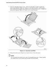
.... 38 Figure 13. Pickup the socket cover (Figure 13, C) and remove it for possible future use. Intel Desktop Board DX79TO Product Guide 7. Close the Load Plate 8. Always replace the socket cover if you remove the processor from the board. Close the load plate (Figure 13, A). Engage the socket lever labeled "OPEN 1st...
.... 38 Figure 13. Pickup the socket cover (Figure 13, C) and remove it for possible future use. Intel Desktop Board DX79TO Product Guide 7. Close the Load Plate 8. Always replace the socket cover if you remove the processor from the board. Close the load plate (Figure 13, A). Engage the socket lever labeled "OPEN 1st...
Product Guide
Page 39
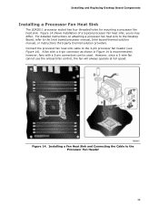
... is recommended; Figure 14 shows installation of a typical processor fan heat sink; For detailed instructions on attaching a processor fan heat sink to the Desktop Board, refer to the 4-pin processor fan header (see Figure 14). Connect the processor fan heat sink cable to the Intel boxed processor manual, Intel boxed thermal solution manual, or instructions third-party...
... is recommended; Figure 14 shows installation of a typical processor fan heat sink; For detailed instructions on attaching a processor fan heat sink to the Desktop Board, refer to the 4-pin processor fan header (see Figure 14). Connect the processor fan heat sink cable to the Intel boxed processor manual, Intel boxed thermal solution manual, or instructions third-party...


