
Product Specification
Page 3
....0032 1,2 G27985-103 BCZ6810H.86A.0032 1,2 G27985-104 BCZ6810H.86A.0032 1,2 G27985-105 BCZ6810H.86A.0039 1,2 Notes: 1. The Z68 processor used on the component side of the following component: Device 82Z68 Platform Controller Hub (PCH) Stepping B3 S-Spec Numbers SLJ4F Errata Current characterized... errata, if any, are documented in a separate Specification Update. See http://developer.intel.com/products/desktop/motherboard/index.htm for the latest documentation. The AA number is found on a small label on this AA ...
....0032 1,2 G27985-103 BCZ6810H.86A.0032 1,2 G27985-104 BCZ6810H.86A.0032 1,2 G27985-105 BCZ6810H.86A.0039 1,2 Notes: 1. The Z68 processor used on the component side of the following component: Device 82Z68 Platform Controller Hub (PCH) Stepping B3 S-Spec Numbers SLJ4F Errata Current characterized... errata, if any, are documented in a separate Specification Update. See http://developer.intel.com/products/desktop/motherboard/index.htm for the latest documentation. The AA number is found on a small label on this AA ...
Product Specification
Page 7
...Summary 11 1.1.2 Board Layout 13 1.1.3 Block Diagram 15 1.2 Legacy Considerations 16 1.3 Online Support 16 1.4 Processor 17 1.4.1 PCI Express x16 Graphics 17 1.5 System Memory 18 1.5.1 Memory Configurations 19 1.6 Intel® Z68 Express Chipset 21 1.7 Graphics Subsystem 21 1.7.1 Integrated Graphics 21 1.7.2 USB 23 1.8 SATA ... Audio Subsystem 26 1.11.1 Audio Subsystem Software 26 1.11.2 Audio Subsystem Components 27 1.12 LAN Subsystem 28 1.12.1 Intel® 82579V Gigabit Ethernet Controller 28 1.12.2 LAN Subsystem Software 29 1.12.3 RJ-45 LAN Connector with Integrated LEDs ...
...Summary 11 1.1.2 Board Layout 13 1.1.3 Block Diagram 15 1.2 Legacy Considerations 16 1.3 Online Support 16 1.4 Processor 17 1.4.1 PCI Express x16 Graphics 17 1.5 System Memory 18 1.5.1 Memory Configurations 19 1.6 Intel® Z68 Express Chipset 21 1.7 Graphics Subsystem 21 1.7.1 Integrated Graphics 21 1.7.2 USB 23 1.8 SATA ... Audio Subsystem 26 1.11.1 Audio Subsystem Software 26 1.11.2 Audio Subsystem Components 27 1.12 LAN Subsystem 28 1.12.1 Intel® 82579V Gigabit Ethernet Controller 28 1.12.2 LAN Subsystem Software 29 1.12.3 RJ-45 LAN Connector with Integrated LEDs ...

Product Specification
Page 10
...BIOS Setup Program Function Keys 62 36. Front-panel Power LED Blink Codes 72 41. SATA Connectors 46 17. States for Intel HD Audio 45 14. Intel Desktop Board DZ68DB Technical Product Specification 11. Component-side Connectors and Headers Shown in Figure 10 44 13. Chassis Intrusion Header 46...Map 41 12. Front Panel Audio Header for a Two-Color Power LED 50 27. Front Panel USB Headers 45 16. S/PDIF Header 46 18. Processor, Front, and Rear Chassis (4-Pin) Fan Headers 46 20. Front Panel CIR Receiver (Input) Header 47 22. Front Panel Header 49 25. ...
...BIOS Setup Program Function Keys 62 36. Front-panel Power LED Blink Codes 72 41. SATA Connectors 46 17. States for Intel HD Audio 45 14. Intel Desktop Board DZ68DB Technical Product Specification 11. Component-side Connectors and Headers Shown in Figure 10 44 13. Chassis Intrusion Header 46...Map 41 12. Front Panel Audio Header for a Two-Color Power LED 50 27. Front Panel USB Headers 45 16. S/PDIF Header 46 18. Processor, Front, and Rear Chassis (4-Pin) Fan Headers 46 20. Front Panel CIR Receiver (Input) Header 47 22. Front Panel Header 49 25. ...
Product Specification
Page 11
... 1 Product Description 1.1 Overview 1.1.1 Feature Summary Table 1 summarizes the major features of the Intel® Z68 Express Platform Controller Hub (PCH) • Integrated graphics support for processors with Intel HD Graphics: ― High Definition Multimedia Interface* (HDMI*) ― DVI-I ―...add-in an LGA1155 socket ― Integrated memory controller with dual channel DDR3 memory support ― Integrated graphics processing (processors with Intel® HD Graphics) ― External graphics interface controller • Four 240-pin DDR3 SDRAM Dual Inline Memory Module ...
... 1 Product Description 1.1 Overview 1.1.1 Feature Summary Table 1 summarizes the major features of the Intel® Z68 Express Platform Controller Hub (PCH) • Integrated graphics support for processors with Intel HD Graphics: ― High Definition Multimedia Interface* (HDMI*) ― DVI-I ―...add-in an LGA1155 socket ― Integrated memory controller with dual channel DDR3 memory support ― Integrated graphics processing (processors with Intel® HD Graphics) ― External graphics interface controller • Four 240-pin DDR3 SDRAM Dual Inline Memory Module ...
Product Specification
Page 14
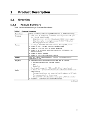
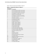
... bus add-in card connector PCI Express x16 bus add-in Figure 1. Intel Desktop Board DZ68DB Technical Product Specification Table 2 lists the components identified in card connector Back panel connectors Processor core power connector (2 x 2) Rear chassis fan header LGA1155 processor socket Processor fan header DIMM 3 (Channel A DIMM 0) DIMM 1 (Channel A DIMM 1) DIMM 4 (... Alternate front panel power LED header Front panel header BIOS Setup configuration jumper block Standby power LED Front panel USB 2.0 headers (4) Intel Z68 Express Chipset S/PDIF out header Front panel audio header 14
... bus add-in card connector PCI Express x16 bus add-in Figure 1. Intel Desktop Board DZ68DB Technical Product Specification Table 2 lists the components identified in card connector Back panel connectors Processor core power connector (2 x 2) Rear chassis fan header LGA1155 processor socket Processor fan header DIMM 3 (Channel A DIMM 0) DIMM 1 (Channel A DIMM 1) DIMM 4 (... Alternate front panel power LED header Front panel header BIOS Setup configuration jumper block Standby power LED Front panel USB 2.0 headers (4) Intel Z68 Express Chipset S/PDIF out header Front panel audio header 14

Product Specification
Page 16
...=hdr+support http://ark.intel.com Supported processors Chipset information BIOS and driver updates Tested memory Integration information http://processormatch.intel.com http://www.intel.com/products/desktop/chipsets/index.htm http://downloadcenter.intel.com http://www.intel.com/support/motherboards/desktop/sb/CS025414.htm http://www.intel.com/support/go/buildit 16 Intel Desktop Board DZ68DB Technical...
...=hdr+support http://ark.intel.com Supported processors Chipset information BIOS and driver updates Tested memory Integration information http://processormatch.intel.com http://www.intel.com/products/desktop/chipsets/index.htm http://downloadcenter.intel.com http://www.intel.com/support/motherboards/desktop/sb/CS025414.htm http://www.intel.com/support/go/buildit 16 Intel Desktop Board DZ68DB Technical...
Product Specification
Page 17
... direction, simultaneously, for providing power to -date list of supported processors. Refer to : http://processormatch.intel.com CAUTION Use only the processors listed on power supply requirements for this board. 1.4.1 PCI Express x16 Graphics The Intel Core i7, Intel Core i5, and Intel Core i3 processors in an LGA1155 socket support discrete add in graphics cards via...
... direction, simultaneously, for providing power to -date list of supported processors. Refer to : http://processormatch.intel.com CAUTION Use only the processors listed on power supply requirements for this board. 1.4.1 PCI Express x16 Graphics The Intel Core i7, Intel Core i5, and Intel Core i3 processors in an LGA1155 socket support discrete add in graphics cards via...
Product Specification
Page 19
... use flex mode, it is necessary to the other . Memory Configuration Examples Refer to single channel operation. Product Description 1.5.1 Memory Configurations The Intel Core i7, Intel Core i5, and Intel Core i3 processors in multiple zones of dual and single channel operation across the whole of memory organization: • Dual channel (Interleaved) mode. This... that is nearest to the 8 GB address space limit), if any, is used . • Single channel (Asymmetric) mode. This mode is mapped to : http://www.intel.com/support/motherboards/desktop/sb/cs011965.htm 19
... use flex mode, it is necessary to the other . Memory Configuration Examples Refer to single channel operation. Product Description 1.5.1 Memory Configurations The Intel Core i7, Intel Core i5, and Intel Core i3 processors in multiple zones of dual and single channel operation across the whole of memory organization: • Dual channel (Interleaved) mode. This... that is nearest to the 8 GB address space limit), if any, is used . • Single channel (Asymmetric) mode. This mode is mapped to : http://www.intel.com/support/motherboards/desktop/sb/cs011965.htm 19
Product Specification
Page 20
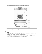
Intel Desktop Board DZ68DB Technical Product Specification Figure 3 illustrates the memory channel and DIMM configuration. Memory Channel and DIMM Configuration NOTE The Intel Core i7, Intel Core i5, and Intel Core i3 processors require memory to be populated in your configuration. 20 Figure 3. For best memory performance always install memory into the blue DIMM memory sockets if only installing two DIMMs in the DIMM 1 (Channel A, DIMM 1) socket.
Intel Desktop Board DZ68DB Technical Product Specification Figure 3 illustrates the memory channel and DIMM configuration. Memory Channel and DIMM Configuration NOTE The Intel Core i7, Intel Core i5, and Intel Core i3 processors require memory to be populated in your configuration. 20 Figure 3. For best memory performance always install memory into the blue DIMM memory sockets if only installing two DIMMs in the DIMM 1 (Channel A, DIMM 1) socket.
Product Specification
Page 21
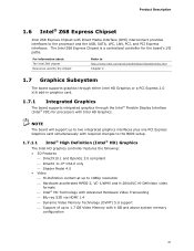
...Memory Technology (DVMT) 5.0 support ⎯ Support of up to 1.7 GB Video Memory with Intel HD Graphics. For information about The Intel Z68 chipset Resources used by the chipset Refer to the processor and the USB, SATA, LPC, LAN, PCI, and PCI Express interfaces. Product Description... 1.6 Intel® Z68 Express Chipset Intel Z68 Express Chipset with Direct Media Interface (DMI) interconnect provides interfaces to http://www.intel.com/products/desktop/chipsets/index...
...Memory Technology (DVMT) 5.0 support ⎯ Support of up to 1.7 GB Video Memory with Intel HD Graphics. For information about The Intel Z68 chipset Resources used by the chipset Refer to the processor and the USB, SATA, LPC, LAN, PCI, and PCI Express interfaces. Product Description... 1.6 Intel® Z68 Express Chipset Intel Z68 Express Chipset with Direct Media Interface (DMI) interconnect provides interfaces to http://www.intel.com/products/desktop/chipsets/index...
Product Specification
Page 30
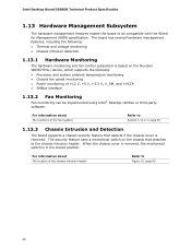
...Wired for Management (WfM) specification. The board has several hardware management features, including the following : • Processor and system ambient temperature monitoring • Chassis fan speed monitoring • Power monitoring of the chassis intrusion header Refer to... be implemented using Intel® Desktop Utilities or third-party software. Intel Desktop Board DZ68DB Technical Product Specification 1.13 Hardware Management Subsystem The hardware management features enable the...
...Wired for Management (WfM) specification. The board has several hardware management features, including the following : • Processor and system ambient temperature monitoring • Chassis fan speed monitoring • Power monitoring of the chassis intrusion header Refer to... be implemented using Intel® Desktop Utilities or third-party software. Intel Desktop Board DZ68DB Technical Product Specification 1.13 Hardware Management Subsystem The hardware management features enable the...
Product Specification
Page 31
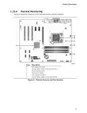
Product Description 1.13.4 Thermal Monitoring Figure 6 shows the locations of the thermal sensors and fan headers. Item A B C D E F Description Rear chassis fan header Thermal diode, located on the processor die Remote thermal diode Processor fan header Front chassis fan header Thermal diode, located on the Intel Z68 PCH Figure 6. Thermal Sensors and Fan Headers 31
Product Description 1.13.4 Thermal Monitoring Figure 6 shows the locations of the thermal sensors and fan headers. Item A B C D E F Description Rear chassis fan header Thermal diode, located on the processor die Remote thermal diode Processor fan header Front chassis fan header Thermal diode, located on the Intel Z68 PCH Figure 6. Thermal Sensors and Fan Headers 31
Product Specification
Page 33
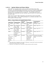
... the system. 33 Table 9 lists the power states supported by battery or external source. Table 9. Power States and Targeted System Power Global States Sleeping States Processor States Device States Targeted System Power (Note 1) G0 - sleeping state S3 - Context saved to the system. Context saved to disk. no power except for a complete...
... the system. 33 Table 9 lists the power states supported by battery or external source. Table 9. Power States and Targeted System Power Global States Sleeping States Processor States Device States Targeted System Power (Note 1) G0 - sleeping state S3 - Context saved to the system. Context saved to disk. no power except for a complete...
Product Specification
Page 44
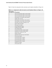
Intel Desktop Board DZ68DB Technical Product Specification Table 12 lists the component-side connectors and headers identified in card connector H Processor core power connector (2 x 2) I Rear chassis fan header J Processor fan header K Front chassis fan header L Chassis intrusion header M LPC Debug header N Consumer IR emitter (output) header O Consumer IR receiver (input) header P Main power connector...
Intel Desktop Board DZ68DB Technical Product Specification Table 12 lists the component-side connectors and headers identified in card connector H Processor core power connector (2 x 2) I Rear chassis fan header J Processor fan header K Front chassis fan header L Chassis intrusion header M LPC Debug header N Consumer IR emitter (output) header O Consumer IR receiver (input) header P Main power connector...
Product Specification
Page 46
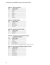
... Panel CIR Emitter (Output) Header Pin Signal Name 1 Emitter out 1 2 Emitter out 2 3 Ground 4 Key (no pin) 4 +5 V DC Table 19. Table 21. Processor, Front, and Rear Chassis (4-Pin) Fan Headers Pin 1 2 3 Signal Name Ground (Note) +12 V FAN_TACH 4 FAN_CONTROL Note: These fan headers use Pulse Width Modulation control for...Ground 2 TXP 3 TXN 4 Ground 5 RXN 6 RXP 7 Ground Table 18. S/PDIF Header Pin Signal Name 1 Ground 2 S/PDIF out 3 Key (no pin) 5 Jack detect 1 6 Jack detect 2 46 Intel Desktop Board DZ68DB Technical Product Specification Table 17.
... Panel CIR Emitter (Output) Header Pin Signal Name 1 Emitter out 1 2 Emitter out 2 3 Ground 4 Key (no pin) 4 +5 V DC Table 19. Table 21. Processor, Front, and Rear Chassis (4-Pin) Fan Headers Pin 1 2 3 Signal Name Ground (Note) +12 V FAN_TACH 4 FAN_CONTROL Note: These fan headers use Pulse Width Modulation control for...Ground 2 TXP 3 TXN 4 Ground 5 RXN 6 RXP 7 Ground Table 18. S/PDIF Header Pin Signal Name 1 Ground 2 S/PDIF out 3 Key (no pin) 5 Jack detect 1 6 Jack detect 2 46 Intel Desktop Board DZ68DB Technical Product Specification Table 17.
Product Specification
Page 48
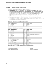
... Ground (Note) Note: When using a power supply with either 2 x 10 or 2 x 12 main power cables. Failure to the processor voltage regulator and must always be unconnected. This connector provides power directly to do so will be used on page 55 48 This connector is... with 2 x 10 connectors previously used . a 2 x 2 connector. Processor Core Power Connector Pin Signal Name Pin Signal Name 1 Ground 3 +12 V 2 Ground 4 +12 V Table 24. a 2 x 12 connector. Intel Desktop Board DZ68DB Technical Product Specification 2.2.2.3 Power Supply Connectors The board has the...
... Ground (Note) Note: When using a power supply with either 2 x 10 or 2 x 12 main power cables. Failure to the processor voltage regulator and must always be unconnected. This connector provides power directly to do so will be used on page 55 48 This connector is... with 2 x 10 connectors previously used . a 2 x 2 connector. Processor Core Power Connector Pin Signal Name Pin Signal Name 1 Ground 3 +12 V 2 Ground 4 +12 V Table 24. a 2 x 12 connector. Intel Desktop Board DZ68DB Technical Product Specification 2.2.2.3 Power Supply Connectors The board has the...
Product Specification
Page 52
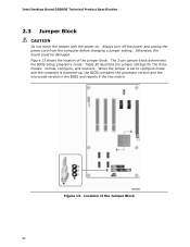
Intel Desktop Board DZ68DB Technical Product Specification 2.3 Jumper Block CAUTION Do not move the jumper with the power on. Location of the jumper block. Table 30 ... block determines the BIOS Setup program's mode. When the jumper is set to configure mode and the computer is powered-up, the BIOS compares the processor version and the microcode version in the BIOS and reports if the two match.
Intel Desktop Board DZ68DB Technical Product Specification 2.3 Jumper Block CAUTION Do not move the jumper with the power on. Location of the jumper block. Table 30 ... block determines the BIOS Setup program's mode. When the jumper is set to configure mode and the computer is powered-up, the BIOS compares the processor version and the microcode version in the BIOS and reports if the two match.
Product Specification
Page 55
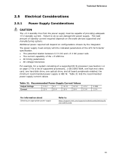
...damage the power supply. Table 31. The power supply must be capable of providing adequate +5 V standby current. Failure to http://support.intel.com/support/motherboards/desktop/sb /CS-026472.htm 55 Technical Reference 2.5 Electrical Considerations 2.5.1 Power Supply Considerations CAUTION The +5 V standby ...8226; All timing parameters • All voltage tolerances For example, for a system consisting of a supported 95 W processor (see Section 1.4 on page 17 for a list of supported processors), 1 GB DDR3 RAM, one high end video card, one hard disk drive, one optical drive, and all ...
...damage the power supply. Table 31. The power supply must be capable of providing adequate +5 V standby current. Failure to http://support.intel.com/support/motherboards/desktop/sb /CS-026472.htm 55 Technical Reference 2.5 Electrical Considerations 2.5.1 Power Supply Considerations CAUTION The +5 V standby ...8226; All timing parameters • All voltage tolerances For example, for a system consisting of a supported 95 W processor (see Section 1.4 on page 17 for a list of supported processors), 1 GB DDR3 RAM, one high end video card, one hard disk drive, one optical drive, and all ...
Product Specification
Page 56
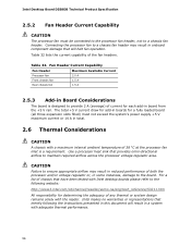
... chassis that merely following website: http://www3.intel.com/cd/channel/reseller/asmo-na/eng/tech_reference/53211.htm All responsibility for a fully loaded board (all three expansion slots filled) must be connected to the processor fan header, not to the following the instructions... presented in this document will halt fan operation. Intel Desktop Board DZ68DB Technical Product Specification 2.5.2 Fan Header Current Capability CAUTION The processor fan must not exceed the system's power supply +5 V maximum current or 14 A in total. 2.6 ...
... chassis that merely following website: http://www3.intel.com/cd/channel/reseller/asmo-na/eng/tech_reference/53211.htm All responsibility for a fully loaded board (all three expansion slots filled) must be connected to the processor fan header, not to the following the instructions... presented in this document will halt fan operation. Intel Desktop Board DZ68DB Technical Product Specification 2.5.2 Fan Header Current Capability CAUTION The processor fan must not exceed the system's power supply +5 V maximum current or 14 A in total. 2.6 ...
Product Specification
Page 57
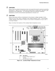
Failure to 120 oC in the processor voltage regulator circuit. Item A B C Description Processor voltage regulator area Processor Intel Z68 Express Chipset Figure 15. Technical Reference CAUTION Ensure that proper airflow is maintained in an open chassis. CAUTION Ensure that the ambient temperature does ...
Failure to 120 oC in the processor voltage regulator circuit. Item A B C Description Processor voltage regulator area Processor Intel Z68 Express Chipset Figure 15. Technical Reference CAUTION Ensure that proper airflow is maintained in an open chassis. CAUTION Ensure that the ambient temperature does ...


