
Product Specification
Page 5
...Memory ...19 1.8 Intel® 845GV Chipset 21 1.8.1 Intel® Extreme Graphics Controller 21 1.8.2 USB ...26 1.8.3 IDE Interfaces 26 1.8.4 Real-Time Clock, CMOS SRAM, and Battery 27 1.9 I/O Controller...28 1.9.1 Serial Ports ...28 1.9.2 Parallel Port 28 1.9.3 Diskette Drive Controller 28 1.9.4 Keyboard and Mouse Interface 28 1.10 Audio Subsystem ...29 1.10.1 Audio Connectors 29 1.10.2 Audio Subsystem Software 30 1.11 LAN Subsystem (Optional 30 1.11.1 Intel® 82562ET Platform LAN Connect Device 30 1.11.2 RJ-45 LAN Connector with Integrated LEDs 31 1.11.3 LAN Subsystem Software...
...Memory ...19 1.8 Intel® 845GV Chipset 21 1.8.1 Intel® Extreme Graphics Controller 21 1.8.2 USB ...26 1.8.3 IDE Interfaces 26 1.8.4 Real-Time Clock, CMOS SRAM, and Battery 27 1.9 I/O Controller...28 1.9.1 Serial Ports ...28 1.9.2 Parallel Port 28 1.9.3 Diskette Drive Controller 28 1.9.4 Keyboard and Mouse Interface 28 1.10 Audio Subsystem ...29 1.10.1 Audio Connectors 29 1.10.2 Audio Subsystem Software 30 1.11 LAN Subsystem (Optional 30 1.11.1 Intel® 82562ET Platform LAN Connect Device 30 1.11.2 RJ-45 LAN Connector with Integrated LEDs 31 1.11.3 LAN Subsystem Software...

Product Specification
Page 6
... BIOS Flash Memory Organization 68 3.3 Resource Configuration 68 3.3.1 PCI Autoconfiguration 68 3.3.2 PCI IDE Support 69 3.4 System Management BIOS (SMBIOS 69 3.5 Legacy USB Support...70 3.6 BIOS Updates ...70 3.6.1 Language Support 71 3.6.2 Custom Splash Screen 71 3.7 Boot Options ...71 3.7.1 CD-ROM Boot 71 3.7.2 Network Boot 71 3.7.3 Booting Without Attached Devices 72 3.7.4 Changing the Default Boot Device During POST 72 3.8 Fast Booting Systems with Intel® Rapid BIOS Boot 73 3.8.1 Peripheral Selection and Configuration 73 3.8.2 Intel Rapid BIOS Boot 73 3.9 BIOS Security...
... BIOS Flash Memory Organization 68 3.3 Resource Configuration 68 3.3.1 PCI Autoconfiguration 68 3.3.2 PCI IDE Support 69 3.4 System Management BIOS (SMBIOS 69 3.5 Legacy USB Support...70 3.6 BIOS Updates ...70 3.6.1 Language Support 71 3.6.2 Custom Splash Screen 71 3.7 Boot Options ...71 3.7.1 CD-ROM Boot 71 3.7.2 Network Boot 71 3.7.3 Booting Without Attached Devices 72 3.7.4 Changing the Default Boot Device During POST 72 3.8 Fast Booting Systems with Intel® Rapid BIOS Boot 73 3.8.1 Peripheral Selection and Configuration 73 3.8.2 Intel Rapid BIOS Boot 73 3.9 BIOS Security...

Product Specification
Page 7
...4.5 BIOS Beep Codes...82 Figures 1. External I /O Map ...40 17. PCI Configuration Space Map 41 19. I/O Shield Dimensions 59 13. Supported Configuration Modes 24 9. Details of the Standby Power Indicator LED on the D845GVFN Board 38 4. Direct Draw Supported Modes 22 7. Wake-up Devices and Events 34 14. Supported DDR DIMM Configurations 20 6. LAN Connector LED States 31 11. Location of bpp Configuration Modes 25 10. Connection Diagram for Front Panel Connector 53 9. Supported System Bus Frequency and Memory Speed Combinations 19 5. Fan Connector...
...4.5 BIOS Beep Codes...82 Figures 1. External I /O Map ...40 17. PCI Configuration Space Map 41 19. I/O Shield Dimensions 59 13. Supported Configuration Modes 24 9. Details of the Standby Power Indicator LED on the D845GVFN Board 38 4. Direct Draw Supported Modes 22 7. Wake-up Devices and Events 34 14. Supported DDR DIMM Configurations 20 6. LAN Connector LED States 31 11. Location of bpp Configuration Modes 25 10. Connection Diagram for Front Panel Connector 53 9. Supported System Bus Frequency and Memory Speed Combinations 19 5. Fan Connector...

Product Specification
Page 8
.... Boot Block Recovery Code Checkpoints 77 51. BIOS Setup Configuration Jumper Settings 57 37. Boot Device Menu Options 72 47. Uncompressed INIT Code Checkpoints 77 50. DC Loading Characteristics 60 38. BIOS Error Messages 75 49. States for a Two-Color Power LED 54 35. Thermal Considerations for Components 62 40. Supervisor and User Password Functions 74 48. Front Chassis Fan Connector 50 29. Product Certification Markings 66 44. BIOS Setup Program Menu Bar 68 45. Intel Desktop Board D845GVFN...
.... Boot Block Recovery Code Checkpoints 77 51. BIOS Setup Configuration Jumper Settings 57 37. Boot Device Menu Options 72 47. Uncompressed INIT Code Checkpoints 77 50. DC Loading Characteristics 60 38. BIOS Error Messages 75 49. States for a Two-Color Power LED 54 35. Thermal Considerations for Components 62 40. Supervisor and User Password Functions 74 48. Front Chassis Fan Connector 50 29. Product Certification Markings 66 44. BIOS Setup Program Menu Bar 68 45. Intel Desktop Board D845GVFN...

Product Specification
Page 10
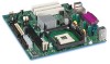
... fan connectors Expansion Capabilities Three PCI bus add-in card connectors (SMBus routed to PCI bus connector 2) BIOS • Intel/AMI BIOS (resident in an mPGA478 socket with a 400/533 MHz system bus • Support for an Intel® Celeron® processor in the 3 Mbit FWH) • Support for Advanced Configuration and Power Interface (ACPI), Plug and Play, and SMBIOS Instantly Available PC Technology • Support for PCI Local Bus Specification Revision 2.2 • Suspend to RAM support • Wake on PCI...
... fan connectors Expansion Capabilities Three PCI bus add-in card connectors (SMBus routed to PCI bus connector 2) BIOS • Intel/AMI BIOS (resident in an mPGA478 socket with a 400/533 MHz system bus • Support for an Intel® Celeron® processor in the 3 Mbit FWH) • Support for Advanced Configuration and Power Interface (ACPI), Plug and Play, and SMBIOS Instantly Available PC Technology • Support for PCI Local Bus Specification Revision 2.2 • Suspend to RAM support • Wake on PCI...

Product Specification
Page 15
... specifications applicable to the Desktop Board D845GVFN. Table 3. Specifications Reference Name AC '97 ACPI ASF ATA/ ATAPI-5 ATX ATX12V BIS DDR SDRAM Specification Title Audio Codec '97 Advanced Configuration and Power Interface Specification Alert Standard Format (ASF) Specification Information Technology-AT Attachment with Packet Interface - 5 (ATA/ATAPI-5) ATX Specification ATX/ATX12V Power Supply Design Guide Boot Integrity Services (BIS) Application Programming Interface (API) Double Data Rate (DDR) SDRAM Specification Design Specification for a 184 Pin...
... specifications applicable to the Desktop Board D845GVFN. Table 3. Specifications Reference Name AC '97 ACPI ASF ATA/ ATAPI-5 ATX ATX12V BIS DDR SDRAM Specification Title Audio Codec '97 Advanced Configuration and Power Interface Specification Alert Standard Format (ASF) Specification Information Technology-AT Attachment with Packet Interface - 5 (ATA/ATAPI-5) ATX Specification ATX/ATX12V Power Supply Design Guide Boot Integrity Services (BIS) Application Programming Interface (API) Double Data Rate (DDR) SDRAM Specification Design Specification for a 184 Pin...

Product Specification
Page 16
...(Enhanced Parallel Port) Bootable CD-ROM Format Specification Low Pin Count Interface Specification microATX Motherboard Interface Specification PCI Local Bus Specification PCI Bus Power Management Interface Specification Plug and Play BIOS Specification Preboot Execution Environment SFX/SFX12V Power Supply Design Guide Version, Revision Date and Ownership Revision 1.0, March 12, 2002, Intel Corporation. Revision 1.0, September 29, 1997, Intel Corporation. Version 2.1, September 20, 1999, Intel Corporation. http://developer.intel.com/te chnology/usb/download/ehc i-r10.pdf http://standards...
...(Enhanced Parallel Port) Bootable CD-ROM Format Specification Low Pin Count Interface Specification microATX Motherboard Interface Specification PCI Local Bus Specification PCI Bus Power Management Interface Specification Plug and Play BIOS Specification Preboot Execution Environment SFX/SFX12V Power Supply Design Guide Version, Revision Date and Ownership Revision 1.0, March 12, 2002, Intel Corporation. Revision 1.0, September 29, 1997, Intel Corporation. Version 2.1, September 20, 1999, Intel Corporation. http://developer.intel.com/te chnology/usb/download/ehc i-r10.pdf http://standards...
Product Specification
Page 29
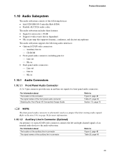
... Line In Connector (Optional) An optional 1 x 4-pin ATAPI-style connector connects the left and right channel signals of an internal audio device to the audio subsystem. Product Description 1.10 Audio Subsystem The audio subsystem consists of the following devices: • Intel 82801DB I /O Connectivity Design Guide Refer to Figure 5, page 48 Table 21, page 49 Section 1.5, page 15 NOTE The front panel audio connector is alternately used as a jumper block for routing audio signals.
... Line In Connector (Optional) An optional 1 x 4-pin ATAPI-style connector connects the left and right channel signals of an internal audio device to the audio subsystem. Product Description 1.10 Audio Subsystem The audio subsystem consists of the following devices: • Intel 82801DB I /O Connectivity Design Guide Refer to Figure 5, page 48 Table 21, page 49 Section 1.5, page 15 NOTE The front panel audio connector is alternately used as a jumper block for routing audio signals.

Product Specification
Page 30
...Full device driver compatibility • ACPI support • Programmable transit threshold • Configuration EEPROM that supports the 82562ET (10/100 Mbit/sec Ethernet) • PCI Power Management ⎯ Supports ACPI technology ⎯ Supports LAN wake capabilities 1.11.1 Intel® 82562ET Platform LAN Connect Device The Intel 82562ET component provides an interface to the audio mixer. Intel Desktop Board D845GVFN Technical Product Specification 1.10.1.3 ATAPI CD-ROM Audio Connector (Optional) An optional 1 x 4-pin ATAPI-style connector connects an internal ATAPI CD-ROM drive to...
...Full device driver compatibility • ACPI support • Programmable transit threshold • Configuration EEPROM that supports the 82562ET (10/100 Mbit/sec Ethernet) • PCI Power Management ⎯ Supports ACPI technology ⎯ Supports LAN wake capabilities 1.11.1 Intel® 82562ET Platform LAN Connect Device The Intel 82562ET component provides an interface to the audio mixer. Intel Desktop Board D845GVFN Technical Product Specification 1.10.1.3 ATAPI CD-ROM Audio Connector (Optional) An optional 1 x 4-pin ATAPI-style connector connects an internal ATAPI CD-ROM drive to...

Product Specification
Page 45
... desktop boards' internal connectors are installed at least 1.5 inches above the main power connector, the diskette drive connector, the IDE connector, and the DIMM sockets. 45 The connectors can be divided into these connectors to power devices external to devices inside the computer's chassis, such as fans and internal peripherals. Do not use these groups: • Back panel I/O connectors (see page 46) ⎯ PS/2 keyboard and mouse ⎯ USB (two ports) ⎯ Parallel port ⎯ Serial port A ⎯ VGA port ⎯ LAN (optional) ⎯ Audio...
... desktop boards' internal connectors are installed at least 1.5 inches above the main power connector, the diskette drive connector, the IDE connector, and the DIMM sockets. 45 The connectors can be divided into these connectors to power devices external to devices inside the computer's chassis, such as fans and internal peripherals. Do not use these groups: • Back panel I/O connectors (see page 46) ⎯ PS/2 keyboard and mouse ⎯ USB (two ports) ⎯ Parallel port ⎯ Serial port A ⎯ VGA port ⎯ LAN (optional) ⎯ Audio...

Product Specification
Page 67
... the BIOS Setup program, POST, the PCI autoconfiguration utility, and Plug and Play support. When the BIOS Setup program configuration jumper is set to configuration mode and the computer is shown below. The BIOS displays a message during POST identifying the type of BIOS Features What This Chapter Contains 3.1 Introduction ...67 3.2 BIOS Flash Memory Organization 68 3.3 Resource Configuration 68 3.4 System Management BIOS (SMBIOS 69 3.5 Legacy USB Support...70 3.6 BIOS Updates ...70 3.7 Boot Options ...71 3.8 Fast Booting Systems with Intel® Rapid BIOS Boot 73 3.9 BIOS Security...
... the BIOS Setup program, POST, the PCI autoconfiguration utility, and Plug and Play support. When the BIOS Setup program configuration jumper is set to configuration mode and the computer is shown below. The BIOS displays a message during POST identifying the type of BIOS Features What This Chapter Contains 3.1 Introduction ...67 3.2 BIOS Flash Memory Organization 68 3.3 Resource Configuration 68 3.4 System Management BIOS (SMBIOS 69 3.5 Legacy USB Support...70 3.6 BIOS Updates ...70 3.7 Boot Options ...71 3.8 Fast Booting Systems with Intel® Rapid BIOS Boot 73 3.9 BIOS Security...

Product Specification
Page 68
... chipset Sets passwords and security features Power Boot Exit Configures power management features Selects boot options and power supply controls Saves or discards changes to Setup program options Table 45 lists the function keys available for the current menu Save the current values and exits the BIOS Setup program Exits the menu For information about the versions of PCI and Plug and Play supported by the add-in cards. Table 44. Intel Desktop Board D845GVFN Technical Product Specification Table 44 lists...
... chipset Sets passwords and security features Power Boot Exit Configures power management features Selects boot options and power supply controls Saves or discards changes to Setup program options Table 45 lists the function keys available for the current menu Save the current values and exits the BIOS Setup program Exits the menu For information about the versions of PCI and Plug and Play supported by the add-in cards. Table 44. Intel Desktop Board D845GVFN Technical Product Specification Table 44 lists...

Product Specification
Page 69
... system types, capabilities, operational status, and installation dates for accessing this information. For example, do not connect an ATA hard drive as event detection and error logging 69 The main component of SMBIOS is a Desktop Management Interface (DMI) compliant method for managing computers in the BIOS Setup program. The IDE interface supports hard drives up the two PCI IDE connectors with drives using any ATAPI compliant devices, including CD-ROM drives, tape drives, and...
... system types, capabilities, operational status, and installation dates for accessing this information. For example, do not connect an ATA hard drive as event detection and error logging 69 The main component of SMBIOS is a Desktop Management Interface (DMI) compliant method for managing computers in the BIOS Setup program. The IDE interface supports hard drives up the two PCI IDE connectors with drives using any ATAPI compliant devices, including CD-ROM drives, tape drives, and...

Product Specification
Page 70
...'s installation instructions. 3.6 BIOS Updates The BIOS can be updated from the BIOS is used . POST completes. 5. Both utilities Verifying that supports USB. The operating system loads. Using this utility, the BIOS can be updated from a file on a hard disk, a 1.44 MB diskette, or a CD-ROM, or from a legacy diskette drive or an LS-120 diskette drive) or a CD-ROM. Using this utility, the BIOS can be used to enter and configure the BIOS Setup program and the maintenance menu. 4. Legacy USB support is no longer used to access the BIOS Setup...
...'s installation instructions. 3.6 BIOS Updates The BIOS can be updated from the BIOS is used . POST completes. 5. Both utilities Verifying that supports USB. The operating system loads. Using this utility, the BIOS can be updated from a file on a hard disk, a 1.44 MB diskette, or a CD-ROM, or from a legacy diskette drive or an LS-120 diskette drive) or a CD-ROM. Using this utility, the BIOS can be used to enter and configure the BIOS Setup program and the maintenance menu. 4. Legacy USB support is no longer used to access the BIOS Setup...

Product Specification
Page 74
... the key at the password prompt of setting the supervisor password and user password. Supervisor and User Password Functions Supervisor Password Set Mode Neither Can change all options (Note) Supervisor only Can change all options User only N/A Supervisor Can change all and user set , the user can enter either the supervisor password or the user password to access Setup. Intel Desktop Board D845GVFN Technical Product Specification 3.9 BIOS Security Features The BIOS includes security features that restrict access to the BIOS Setup program and who can boot...
... the key at the password prompt of setting the supervisor password and user password. Supervisor and User Password Functions Supervisor Password Set Mode Neither Can change all options (Note) Supervisor only Can change all options User only N/A Supervisor Can change all and user set , the user can enter either the supervisor password or the user password to access Setup. Intel Desktop Board D845GVFN Technical Product Specification 3.9 BIOS Security Features The BIOS includes security features that restrict access to the BIOS Setup program and who can boot...

Product Specification
Page 77
... necessary chipset initialization, start memory refresh, and do memory sizing. Control is Disabled. Copy main BIOS image to F000 shadow RAM and give control to main BIOS. Initialize floppy drive. Give two beeps. If the POST fails, execution stops and the last POST code generated is initialized. The POST card can decode the port and display the contents on a medium such as a seven-segment display. Onboard KBC, RTC enabled (if present). Uncompress the main BIOS module. Retry the booting...
... necessary chipset initialization, start memory refresh, and do memory sizing. Control is Disabled. Copy main BIOS image to F000 shadow RAM and give control to main BIOS. Initialize floppy drive. Give two beeps. If the POST fails, execution stops and the last POST code generated is initialized. The POST card can decode the port and display the contents on a medium such as a seven-segment display. Onboard KBC, RTC enabled (if present). Uncompress the main BIOS module. Retry the booting...

Product Specification
Page 78
.... Intel Desktop Board D845GVFN Technical Product Specification Table 51. BIOS stack set . Any initialization after video ROM returns control. Going to begin . To do alternate Display memory R/W test. Interrupt vector initialization to issue Pin-23,24 blocking/unblocking command. Going for any . To give control to look for details of , key during power-on. About to do display memory R/W test. Display mode to start . Different buses init (input, IPL, general devices...
.... Intel Desktop Board D845GVFN Technical Product Specification Table 51. BIOS stack set . Any initialization after video ROM returns control. Going to begin . To do alternate Display memory R/W test. Interrupt vector initialization to issue Pin-23,24 blocking/unblocking command. Going for any . To give control to look for details of , key during power-on. About to do display memory R/W test. Display mode to start . Different buses init (input, IPL, general devices...

Product Specification
Page 79
... mode. Memory size calculation over . Check for memory wrap around at 0:0 and finding the total system memory size. Memory testing/initialization above 1M found and verified. Going to start DMA and interrupt controller test. About to clear Hit message. DMA#2 base register test passed. Extended NMI sources enabling is saved. Keyboard reset error/stuck key found and verified. Runtime Code Uncompressed in extended memory. Going to enter in virtual mode...
... mode. Memory size calculation over . Check for memory wrap around at 0:0 and finding the total system memory size. Memory testing/initialization above 1M found and verified. Going to start DMA and interrupt controller test. About to clear Hit message. DMA#2 base register test passed. Extended NMI sources enabling is saved. Keyboard reset error/stuck key found and verified. Runtime Code Uncompressed in extended memory. Going to enter in virtual mode...

Product Specification
Page 80
... AD Description of different buses optional ROMs from E000 ROM control. Soft error display complete. Going to display power-on screen message. Going to set keyboard typematic rate. Floppy setup complete. To display soft error and check for multiprocessor support (if present). First screen message displayed. message displayed. Runtime Code Uncompressed in Shadow. Hard disk controller reset done. NMI and parity enabled. Initialization after RS-232 base address. Intel Desktop Board D845GVFN Technical Product Specification Table 51. Programming after...
... AD Description of different buses optional ROMs from E000 ROM control. Soft error display complete. Going to display power-on screen message. Going to set keyboard typematic rate. Floppy setup complete. To display soft error and check for multiprocessor support (if present). First screen message displayed. message displayed. Runtime Code Uncompressed in Shadow. Hard disk controller reset done. NMI and parity enabled. Initialization after RS-232 base address. Intel Desktop Board D845GVFN Technical Product Specification Table 51. Programming after...

Product Specification
Page 82
... BIOS displays an error message describing the problem (see Table 55). The BIOS also issues a beep code (one long tone followed by a series of the onboard speaker on the Desktop Board D845GVFN Refer to Figure 1, on the beep codes issued, check the documentation for example, a video BIOS) can also issue audible errors, usually consisting of one long tone followed by two short tones) during POST if the video configuration fails (a faulty video card or no card installed...
... BIOS displays an error message describing the problem (see Table 55). The BIOS also issues a beep code (one long tone followed by a series of the onboard speaker on the Desktop Board D845GVFN Refer to Figure 1, on the beep codes issued, check the documentation for example, a video BIOS) can also issue audible errors, usually consisting of one long tone followed by two short tones) during POST if the video configuration fails (a faulty video card or no card installed...


