
Product Specification
Page 7
...120 4.4.8 USB Configuration Submenu 121 4.4.9 Chipset Configuration Submenu 122 4.4.10 Fan Control Configuration Submenu 124 4.4.11 Hardware Monitoring 125 4.5 Security Menu ...126 4.6 Power Menu ...127 4.6.1 ACPI Submenu 127 4.7 Boot Menu ...128 4.7.1 Boot Device Priority Submenu 129 4.7.2 Hard Disk Drives Submenu 130 4.7.3 Removable Devices Submenu 130 4.7.4 ATAPI CD-ROM Drives Submenu 131 4.8 Exit Menu ...131 5 Error Messages and Beep Codes 5.1 BIOS Error Messages 133 5.2 Port 80h POST Codes 135 5.3 Bus Initialization Checkpoints 139 5.4 Speaker ...140 5.5 BIOS Beep Codes ...140...
...120 4.4.8 USB Configuration Submenu 121 4.4.9 Chipset Configuration Submenu 122 4.4.10 Fan Control Configuration Submenu 124 4.4.11 Hardware Monitoring 125 4.5 Security Menu ...126 4.6 Power Menu ...127 4.6.1 ACPI Submenu 127 4.7 Boot Menu ...128 4.7.1 Boot Device Priority Submenu 129 4.7.2 Hard Disk Drives Submenu 130 4.7.3 Removable Devices Submenu 130 4.7.4 ATAPI CD-ROM Drives Submenu 131 4.8 Exit Menu ...131 5 Error Messages and Beep Codes 5.1 BIOS Error Messages 133 5.2 Port 80h POST Codes 135 5.3 Bus Initialization Checkpoints 139 5.4 Speaker ...140 5.5 BIOS Beep Codes ...140...

Product Specification
Page 8
... Block Diagram 44 13. Location of Single Channel Configuration without Dynamic Mode 28 9. Power and Hardware Control Connectors 73 21. External I /O Shield Dimensions 87 30. Desktop Board D865GLC Dimensions 86 29. Specifications ...18 5. Supported Modes for DDR266 Dual Channel and DDR333/DDR400 Single Channel Configurations 34 12. Localized High Temperature Zones 90 Tables 1. Supported Memory Configurations 23 7. Characteristics of Dual Channel Configuration without Dynamic Mode.....24 8. LAN Connector LED Locations 46 14. Audio Connectors ...71 20. Desktop Board...
... Block Diagram 44 13. Location of Single Channel Configuration without Dynamic Mode 28 9. Power and Hardware Control Connectors 73 21. External I /O Shield Dimensions 87 30. Desktop Board D865GLC Dimensions 86 29. Specifications ...18 5. Supported Modes for DDR266 Dual Channel and DDR333/DDR400 Single Channel Configurations 34 12. Localized High Temperature Zones 90 Tables 1. Supported Memory Configurations 23 7. Characteristics of Dual Channel Configuration without Dynamic Mode.....24 8. LAN Connector LED Locations 46 14. Audio Connectors ...71 20. Desktop Board...

Product Specification
Page 9
... CD-ROM Connector 72 28. PCI Interrupt Routing Map 67 26. Fan Connector Current Capability 88 45. BIOS Setup Program Menu Bar 105 54. BIOS Setup Program Function Keys 106 55. Maintenance Menu 106 56. System Memory Map 61 20. Desktop Board D865GBF/D865GLC Environmental Specifications 92 48. LAN Connector LED States 47 14. Boot Device Menu Options 102 52. Main Menu...107 57. Contents 13. States for a Two-Color Power LED 81 41. SCSI Hard Drive Activity LED Connector (Optional 78...
... CD-ROM Connector 72 28. PCI Interrupt Routing Map 67 26. Fan Connector Current Capability 88 45. BIOS Setup Program Menu Bar 105 54. BIOS Setup Program Function Keys 106 55. Maintenance Menu 106 56. System Memory Map 61 20. Desktop Board D865GBF/D865GLC Environmental Specifications 92 48. LAN Connector LED States 47 14. Boot Device Menu Options 102 52. Main Menu...107 57. Contents 13. States for a Two-Color Power LED 81 41. SCSI Hard Drive Activity LED Connector (Optional 78...

Product Specification
Page 13
... range power supply voltages • Thermal sense to detect out of range thermal values • Three fan connectors • Three fan sense inputs used to monitor fan activity • Fan speed control For information about Available configurations for PCI Local Bus Specification Revision 2.2 • Suspend to RAM support • Wake on the Desktop Boards D865GBF and D865GLC. Manufacturing Options SCSI Hard Drive Activity LED Connector Allows add-in all marketing channels. Product Description Table 2. Please contact your Intel...
... range power supply voltages • Thermal sense to detect out of range thermal values • Three fan connectors • Three fan sense inputs used to monitor fan activity • Fan speed control For information about Available configurations for PCI Local Bus Specification Revision 2.2 • Suspend to RAM support • Wake on the Desktop Boards D865GBF and D865GLC. Manufacturing Options SCSI Hard Drive Activity LED Connector Allows add-in all marketing channels. Product Description Table 2. Please contact your Intel...

Product Specification
Page 16
...Bus VGA Port Channel A DIMMs (2) Channel B DIMMs (2) Display Interface Dual-Channel Memory Bus SMBus PCI Bus PCI Slot 1 PCI Slot 2 PCI Slot 3 PCI Slot 4 PCI Slot 5 PCI Slot 6 SMBus D865GBF Only Hardware Monitoring and Fan Control ASIC USB LPC Bus I/O Controller LPC Bus Back Panel/ Front Panel USB Ports Serial Port Parallel Port PS/2 Mouse PS/2 Keyboard Diskette Drive Connector Intel 82801EB I/O Controller Hub (ICH5) Intel 82802AB 4 Mbit Firmware Hub (FWH) Intel 865G Chipset CSMA/CD Unit Interface 10/100 LAN PLC (Optional) LAN Connector AC Link Serial ATA IDE Interface Serial...
...Bus VGA Port Channel A DIMMs (2) Channel B DIMMs (2) Display Interface Dual-Channel Memory Bus SMBus PCI Bus PCI Slot 1 PCI Slot 2 PCI Slot 3 PCI Slot 4 PCI Slot 5 PCI Slot 6 SMBus D865GBF Only Hardware Monitoring and Fan Control ASIC USB LPC Bus I/O Controller LPC Bus Back Panel/ Front Panel USB Ports Serial Port Parallel Port PS/2 Mouse PS/2 Keyboard Diskette Drive Connector Intel 82801EB I/O Controller Hub (ICH5) Intel 82802AB 4 Mbit Firmware Hub (FWH) Intel 865G Chipset CSMA/CD Unit Interface 10/100 LAN PLC (Optional) LAN Connector AC Link Serial ATA IDE Interface Serial...

Product Specification
Page 41
...) support • Serial IRQ interface compatible with 3.3 VSB applied. ✏ NOTE If the battery and AC power fail, custom defaults, if previously saved, will be wired to use the same LED as the onboard IDE controller. The clock is accurate to http://www.smsc.com/ http://www.national.com/ 41 Product Description 1.8.4.3 SCSI Hard Drive Activity LED Connector (Optional) The SCSI hard drive activity LED connector is a 1 x 2-pin connector that allows an add-in hard drive controller...
...) support • Serial IRQ interface compatible with 3.3 VSB applied. ✏ NOTE If the battery and AC power fail, custom defaults, if previously saved, will be wired to use the same LED as the onboard IDE controller. The clock is accurate to http://www.smsc.com/ http://www.national.com/ 41 Product Description 1.8.4.3 SCSI Hard Drive Activity LED Connector (Optional) The SCSI hard drive activity LED connector is a 1 x 2-pin connector that allows an add-in hard drive controller...

Product Specification
Page 68
...; PS/2 keyboard and mouse USB (four ports) Parallel port Serial port A VGA port LAN Audio (line out, line in, and mic in) • Internal I/O connectors (see page 70) Audio (auxiliary line input, ATAPI CD-ROM, and front panel audio) Fans [three] Power Add-in boards (PCI and AGP) Parallel ATA IDE Diskette drive SCSI hard drive activity LED (optional) Chassis intrusion Serial ATA...
...; PS/2 keyboard and mouse USB (four ports) Parallel port Serial port A VGA port LAN Audio (line out, line in, and mic in) • Internal I/O connectors (see page 70) Audio (auxiliary line input, ATAPI CD-ROM, and front panel audio) Fans [three] Power Add-in boards (PCI and AGP) Parallel ATA IDE Diskette drive SCSI hard drive activity LED (optional) Chassis intrusion Serial ATA...

Product Specification
Page 76
... Board D865GBF. This enables PCI bus add-in Board and Peripheral Interface Connectors 76 A BCDE F G Item A B C D E F G 2 1 1 2 1 M L KJ 40 39 2 34 33 39 1 I H Description PCI bus connector 6 PCI bus connector 5 PCI bus connector 4 PCI bus connector 3 PCI bus connector 2 PCI bus connector 1 AGP connector Item H I J K L M OM15921 Description Diskette drive Primary Parallel ATA IDE [black] Secondary Parallel ATA IDE [white] SCSI hard drive activity LED (optional) Serial ATA connector 1 Serial ATA connector 0 Figure 21. The specific SMBus signals are routed to PCI bus connector...
... Board D865GBF. This enables PCI bus add-in Board and Peripheral Interface Connectors 76 A BCDE F G Item A B C D E F G 2 1 1 2 1 M L KJ 40 39 2 34 33 39 1 I H Description PCI bus connector 6 PCI bus connector 5 PCI bus connector 4 PCI bus connector 3 PCI bus connector 2 PCI bus connector 1 AGP connector Item H I J K L M OM15921 Description Diskette drive Primary Parallel ATA IDE [black] Secondary Parallel ATA IDE [white] SCSI hard drive activity LED (optional) Serial ATA connector 1 Serial ATA connector 0 Figure 21. The specific SMBus signals are routed to PCI bus connector...

Product Specification
Page 98
... configure PCI devices. Autoconfiguration lets a user insert or remove PCI cards without having to PIO Mode 3 or 4, depending on the system after adding a PCI card, the BIOS automatically configures interrupts, the I /O channel support. When a user turns on the capability of ATAPI). PCI devices may be available for the supported version of the drive. Intel Desktop Board D865GBF/D865GLC Technical Product Specification 3.3 Resource Configuration 3.3.1 PCI Autoconfiguration The BIOS can override the auto-configuration options by specifying manual configuration in the BIOS Setup...
... configure PCI devices. Autoconfiguration lets a user insert or remove PCI cards without having to PIO Mode 3 or 4, depending on the system after adding a PCI card, the BIOS automatically configures interrupts, the I /O channel support. When a user turns on the capability of ATAPI). PCI devices may be available for the supported version of the drive. Intel Desktop Board D865GBF/D865GLC Technical Product Specification 3.3 Resource Configuration 3.3.1 PCI Autoconfiguration The BIOS can override the auto-configuration options by specifying manual configuration in the BIOS Setup...

Product Specification
Page 105
... Clears passwords and displays processor information Displays processor and memory configuration Configures advanced features available through the chipset Sets passwords and security features Power Boot Configures power management features and power supply controls Selects boot options Exit Saves or discards changes to view and change the BIOS settings for the computer. The BIOS Setup program is in configure mode. 105 Table 53. however, the maintenance menu is displayed only when the Desktop Board is accessed by pressing the key after the Power-On Self-Test (POST) memory...
... Clears passwords and displays processor information Displays processor and memory configuration Configures advanced features available through the chipset Sets passwords and security features Power Boot Configures power management features and power supply controls Selects boot options Exit Saves or discards changes to view and change the BIOS settings for the computer. The BIOS Setup program is in configure mode. 105 Table 53. however, the maintenance menu is displayed only when the Desktop Board is accessed by pressing the key after the Power-On Self-Test (POST) memory...

Product Specification
Page 106
... submenu Load the default configuration values for configure mode setting information. Maintenance Main Advanced Security Power Boot Exit The menu shown in configure mode. Setup only displays this menu, select Maintenance on page 84 for the current menu Save the current values and exits the BIOS Setup program Exits the menu 4.2 Maintenance Menu To access this menu in Table 55 is for menu screens. Displays CPU's Stepping Signature. Table 55. Table 54. Maintenance Menu Feature Options Clear All Passwords CPU Stepping...
... submenu Load the default configuration values for configure mode setting information. Maintenance Main Advanced Security Power Boot Exit The menu shown in configure mode. Setup only displays this menu, select Maintenance on page 84 for the current menu Save the current values and exits the BIOS Setup program Exits the menu 4.2 Maintenance Menu To access this menu in Table 55 is for menu screens. Displays CPU's Stepping Signature. Table 55. Table 54. Maintenance Menu Feature Options Clear All Passwords CPU Stepping...

Product Specification
Page 113
... onboard LAN device. 113 BIOS Setup Program Table 60. Not available if the • Bi-directional parallel port is disabled. (default) Output Only operates in AT*-compatible mode. • EPP Bi-directional operates in PS/2-compatible mode. • ECP EPP is set to Enabled) DMA (This feature is present only when Parallel Port Mode is Extended Parallel Port mode, a high-speed bi-directional mode. Specifies the DMA channel. • Enabled (default) • Disabled • Enabled (default) • Disabled Enables...
... onboard LAN device. 113 BIOS Setup Program Table 60. Not available if the • Bi-directional parallel port is disabled. (default) Output Only operates in AT*-compatible mode. • EPP Bi-directional operates in PS/2-compatible mode. • ECP EPP is set to Enabled) DMA (This feature is present only when Parallel Port Mode is Extended Parallel Port mode, a high-speed bi-directional mode. Specifies the DMA channel. • Enabled (default) • Disabled • Enabled (default) • Disabled Enables...

Product Specification
Page 117
BIOS Setup Program Table 62. SATA/PATA Submenus Feature Drive Installed Type Maximum Capacity LBA/Large Mode Block Mode PIO Mode DMA Mode S.M.A.R.T. Auto fills-in the above table. Displays whether automatic translation mode is enabled for the drive. Auto = Auto-detected SWDMAn = Single Word DMAn SWDMAn = Multi Word DMAn UDMAn = Ultra DMAn (This item is read-only unless Type is set to User.) Enables/disables S.M.A.R.T. (Self-Monitoring, Analysis, and Reporting Technology). (This item is...
BIOS Setup Program Table 62. SATA/PATA Submenus Feature Drive Installed Type Maximum Capacity LBA/Large Mode Block Mode PIO Mode DMA Mode S.M.A.R.T. Auto fills-in the above table. Displays whether automatic translation mode is enabled for the drive. Auto = Auto-detected SWDMAn = Single Word DMAn SWDMAn = Multi Word DMAn UDMAn = Ultra DMAn (This item is read-only unless Type is set to User.) Enables/disables S.M.A.R.T. (Self-Monitoring, Analysis, and Reporting Technology). (This item is...

Product Specification
Page 118
... drive A. Disables or enables write protection for configuring the diskette drive. Table 63. Maintenance Main Advanced Security Power PCI Configuration Boot Configuration Peripheral Configuration Drive Configuration Floppy Configuration Event Log Configuration Video Configuration USB Configuration Chipset Configuration Fan Control Configuration Hardware Monitoring Boot Exit The submenu represented by Table 63 is used for the diskette drive. 118 Intel Desktop Board D865GBF/D865GLC Technical Product Specification 4.4.5 Floppy Configuration Submenu To access this menu, select...
... drive A. Disables or enables write protection for configuring the diskette drive. Table 63. Maintenance Main Advanced Security Power PCI Configuration Boot Configuration Peripheral Configuration Drive Configuration Floppy Configuration Event Log Configuration Video Configuration USB Configuration Chipset Configuration Fan Control Configuration Hardware Monitoring Boot Exit The submenu represented by Table 63 is used for the diskette drive. 118 Intel Desktop Board D865GBF/D865GLC Technical Product Specification 4.4.5 Floppy Configuration Submenu To access this menu, select...

Product Specification
Page 123
... in memory. Corresponds to Manual - Notes: 1. This feature is displayed only if SDRAM Timing Control is set to tRAS. User Defined. 123 User Defined • 8 • 7 • 6 (default) • 5 • 2.0 • 2.5 (default) • 3.0 • 4 • 3 (default) • 2 • 4 • 3 (default) • 2 Description Controls the CPC/1n rule mode. Manual - Selects the length of detected SDRAM settings. This option is displayed only if the installed processor has a 533 MHz system bus. 3. Auto...
... in memory. Corresponds to Manual - Notes: 1. This feature is displayed only if SDRAM Timing Control is set to tRAS. User Defined. 123 User Defined • 8 • 7 • 6 (default) • 5 • 2.0 • 2.5 (default) • 3.0 • 4 • 3 (default) • 2 • 4 • 3 (default) • 2 Description Controls the CPC/1n rule mode. Manual - Selects the length of detected SDRAM settings. This option is displayed only if the installed processor has a 533 MHz system bus. 3. Auto...
Product Specification
Page 124
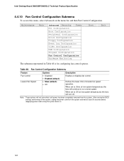
... system temperatures the fans will continue to Off, at least 30 seconds before reapplying power and turning the system back on the menu bar and then Fan Control Configuration. Maintenance Main Advanced Security Power PCI Configuration Boot Configuration Peripheral Configuration Drive Configuration Floppy Configuration Event Log Configuration Video Configuration USB Configuration Chipset Configuration Fan Control Configuration Hardware Monitoring Boot Exit The submenu represented in Table 68 is for configuring fan control options. Defines the lower limit of chassis fan speed operation...
... system temperatures the fans will continue to Off, at least 30 seconds before reapplying power and turning the system back on the menu bar and then Fan Control Configuration. Maintenance Main Advanced Security Power PCI Configuration Boot Configuration Peripheral Configuration Drive Configuration Floppy Configuration Event Log Configuration Video Configuration USB Configuration Chipset Configuration Fan Control Configuration Hardware Monitoring Boot Exit The submenu represented in Table 68 is for configuring fan control options. Defines the lower limit of chassis fan speed operation...

Product Specification
Page 128
... available types of POST messages. Table 73. Note: When set the boot features and the boot sequence. Specifies the boot sequence from the available hard disk drives. Intel Desktop Board D865GBF/D865GLC Technical Product Specification 4.7 Boot Menu To access this menu, select Boot from the available ATAPI CD-ROM drives. 128 Specifies the boot sequence from the menu bar at the top of the screen. Maintenance Main Advanced Security Power Boot Exit Boot Device Priority Hard Disk Drives Removable Devices ATAPI CD-ROM Drives The menu...
... available types of POST messages. Table 73. Note: When set the boot features and the boot sequence. Specifies the boot sequence from the available hard disk drives. Intel Desktop Board D865GBF/D865GLC Technical Product Specification 4.7 Boot Menu To access this menu, select Boot from the available ATAPI CD-ROM drives. 128 Specifies the boot sequence from the menu bar at the top of the screen. Maintenance Main Advanced Security Power Boot Exit Boot Device Priority Hard Disk Drives Removable Devices ATAPI CD-ROM Drives The menu...

Product Specification
Page 135
... point where an error occurred. Table 80 defines the uncompressed INIT code checkpoints, Table 81 describes the boot block recovery code checkpoints, and Table 82 lists the runtime code uncompressed in PCI bus connector 1. Onboard KBC, RTC enabled (if present). Init code to be copied to segment 0 and control to be installed in F000 shadow RAM. EC Try to boot from ATAPI. Verify base memory. Copy main BIOS image to...
... point where an error occurred. Table 80 defines the uncompressed INIT code checkpoints, Table 81 describes the boot block recovery code checkpoints, and Table 82 lists the runtime code uncompressed in PCI bus connector 1. Onboard KBC, RTC enabled (if present). Init code to be copied to segment 0 and control to be installed in F000 shadow RAM. EC Try to boot from ATAPI. Verify base memory. Copy main BIOS image to...

Product Specification
Page 137
... to issue keyboard reset command. 81 Keyboard reset error/stuck key found. Going to save the memory size. (Go to check point # 52h). 4E Memory test started . Memory above 1M found and verified. Going to display the first 64k memory size. 4F Memory size display started . (NOT SOFT RESET) About to enter in real mode. 54 Shutdown successful, CPU in base 640k memory. To initialize 8259 interrupt controller. 7F Extended NMI sources enabling is saved...
... to issue keyboard reset command. 81 Keyboard reset error/stuck key found. Going to save the memory size. (Go to check point # 52h). 4E Memory test started . Memory above 1M found and verified. Going to display the first 64k memory size. 4F Memory size display started . (NOT SOFT RESET) About to enter in real mode. 54 Shutdown successful, CPU in base 640k memory. To initialize 8259 interrupt controller. 7F Extended NMI sources enabling is saved...

Product Specification
Page 140
... speaker provides audible error code (beep code) information during POST if the video configuration fails (a faulty video card or no card installed) or if an external ROM module does not properly checksum to zero. For information about The location of the onboard speaker on the Desktop Board D865GBF The location of the onboard speaker on the Desktop Board D865GLC Refer to initialize the video and writes the error in the upper left corner of the screen (using...
... speaker provides audible error code (beep code) information during POST if the video configuration fails (a faulty video card or no card installed) or if an external ROM module does not properly checksum to zero. For information about The location of the onboard speaker on the Desktop Board D865GBF The location of the onboard speaker on the Desktop Board D865GLC Refer to initialize the video and writes the error in the upper left corner of the screen (using...


