
Product Specification
Page 7
... Panel Connector 74 22. High Definition Audio Subsystem Block Diagram 34 12. LAN Connector LED Locations 37 14. Thermal Monitoring for IEEE 1394a Connectors 76 24. Detailed System Memory Address Map 56 18. Dual Channel (Interleaved) Mode Configuration with One DIMM 25 9. Location of the Standby Power Indicator LED 47 17. D915GAV Board Components 14 2. Single Channel (Asymmetric) Mode Configuration with Three DIMMs 23 7. Block Diagram...18 4. Contents 3.6 BIOS Updates ...94 3.6.1 Language Support 94 3.6.2 Custom Splash Screen 94 3.7 Boot Options...
... Panel Connector 74 22. High Definition Audio Subsystem Block Diagram 34 12. LAN Connector LED Locations 37 14. Thermal Monitoring for IEEE 1394a Connectors 76 24. Detailed System Memory Address Map 56 18. Dual Channel (Interleaved) Mode Configuration with One DIMM 25 9. Location of the Standby Power Indicator LED 47 17. D915GAV Board Components 14 2. Single Channel (Asymmetric) Mode Configuration with Three DIMMs 23 7. Block Diagram...18 4. Contents 3.6 BIOS Updates ...94 3.6.1 Language Support 94 3.6.2 Custom Splash Screen 94 3.7 Boot Options...

Product Specification
Page 8
Localized High Temperature Zones 84 Tables 1. ATAPI CD-ROM Connector (Optional 70 24. Serial Port B Connector (optional 70 26. SCSI Hard Drive Activity LED Connector (Optional 71 28. ATX12V Power Connector 73 33. States for Components 85 42. Thermal Considerations for a One-Color Power LED 75 37. D915GAG Board Components Shown in Figure 1 15 5. Supported System Bus Frequency and Memory Speed Combinations 20 7. PCI Configuration Space Map 59 17. S/PDIF Connector (Optional 70 23. Serial ATA Connectors 71 29. DC Loading Characteristics...
Localized High Temperature Zones 84 Tables 1. ATAPI CD-ROM Connector (Optional 70 24. Serial Port B Connector (optional 70 26. SCSI Hard Drive Activity LED Connector (Optional 71 28. ATX12V Power Connector 73 33. States for Components 85 42. Thermal Considerations for a One-Color Power LED 75 37. D915GAG Board Components Shown in Figure 1 15 5. Supported System Bus Frequency and Memory Speed Combinations 20 7. PCI Configuration Space Map 59 17. S/PDIF Connector (Optional 70 23. Serial ATA Connectors 71 29. DC Loading Characteristics...

Product Specification
Page 11
... What This Chapter Contains 1.1 PCI Bus Terminology Change 11 1.2 Board Differences ...11 1.3 Overview ...12 1.4 Online Support ...19 1.5 Processor ...19 1.6 System Memory ...20 1.7 Intel® 915G Chipset ...26 1.8 PCI Express Connectors 30 1.9 I/O Controller...31 1.10 Audio Subsystem ...32 1.11 LAN Subsystem ...35 1.12 Hardware Management Subsystem 38 1.13 Power Management ...41 1.14 Trusted Platform Module (Optional 48 1.1 PCI Bus Terminology Change Previous generations of Intel® Desktop Boards used an add-in card connector referred to as...
... What This Chapter Contains 1.1 PCI Bus Terminology Change 11 1.2 Board Differences ...11 1.3 Overview ...12 1.4 Online Support ...19 1.5 Processor ...19 1.6 System Memory ...20 1.7 Intel® 915G Chipset ...26 1.8 PCI Express Connectors 30 1.9 I/O Controller...31 1.10 Audio Subsystem ...32 1.11 LAN Subsystem ...35 1.12 Hardware Management Subsystem 38 1.13 Power Management ...41 1.14 Trusted Platform Module (Optional 48 1.1 PCI Bus Terminology Change Previous generations of Intel® Desktop Boards used an add-in card connector referred to as...

Product Specification
Page 13
... an internal CD-ROM drive to the onboard audio subsystem ATX fan connector Additional fan connector for the Desktop Boards D915GAV and D915GAG Refer to use in larger chassis (D915GAV board only) IEEE-1394a Interface IEEE-1394a controller and three IEEE-1394a connectors (one back panel connector, two front-panel connectors) LAN subsystem The D915GAG board provides one on the D915GAG) • One PCI Express x16 bus add-in card connector (both boards) Instantly Available PC Technology • Support for PCI Local Bus Specification...
... an internal CD-ROM drive to the onboard audio subsystem ATX fan connector Additional fan connector for the Desktop Boards D915GAV and D915GAG Refer to use in larger chassis (D915GAV board only) IEEE-1394a Interface IEEE-1394a controller and three IEEE-1394a connectors (one back panel connector, two front-panel connectors) LAN subsystem The D915GAG board provides one on the D915GAG) • One PCI Express x16 bus add-in card connector (both boards) Instantly Available PC Technology • Support for PCI Local Bus Specification...

Product Specification
Page 18
... PCI Express x1 Slot 1 PCI Express x1 Slot 2 D915GAV only Parallel ATA IDE Connector Parallel ATA IDE Interface LGA775 Processor Socket System Bus (800/533 MHz) PCI Express x16 Interface PCI Express x16 Connector Intel 82915G Graphics and Memory Controller Hub (GMCH) VGA Port Channel A DIMMs (2) Display Interface Dual-Channel Memory Bus SMBus Channel B DIMMs (2) Gigabit Ethernet Controller (Optional) D915GAG only LAN Connector USB Back Panel/Front Panel USB Ports LPC Bus I/O Controller LPC Bus Serial Ports Parallel Port PS/2 Mouse PS/2 Keyboard Diskette Drive Connector Intel...
... PCI Express x1 Slot 1 PCI Express x1 Slot 2 D915GAV only Parallel ATA IDE Connector Parallel ATA IDE Interface LGA775 Processor Socket System Bus (800/533 MHz) PCI Express x16 Interface PCI Express x16 Connector Intel 82915G Graphics and Memory Controller Hub (GMCH) VGA Port Channel A DIMMs (2) Display Interface Dual-Channel Memory Bus SMBus Channel B DIMMs (2) Gigabit Ethernet Controller (Optional) D915GAG only LAN Connector USB Back Panel/Front Panel USB Ports LPC Bus I/O Controller LPC Bus Serial Ports Parallel Port PS/2 Mouse PS/2 Keyboard Diskette Drive Connector Intel...

Product Specification
Page 26
...; High performance 3-D setup and render engine • High quality/performance texture engine • Display ⎯ Integrated 24-bit 400 MHz RAMDAC ⎯ DDC2B compliant interface 26 When a PCI Express x16 add-in card can be used , or a PCI Express x16 add-in card is installed, the GMA900 graphics controller is disabled. 1.7.1.1 Intel® GMA900 Graphics Controller The Intel GMA900 graphics controller features the following devices: • Intel 82915G Graphics Memory Controller Hub (GMCH) with DMI interconnect • Firmware...
...; High performance 3-D setup and render engine • High quality/performance texture engine • Display ⎯ Integrated 24-bit 400 MHz RAMDAC ⎯ DDC2B compliant interface 26 When a PCI Express x16 add-in card can be used , or a PCI Express x16 add-in card is installed, the GMA900 graphics controller is disabled. 1.7.1.1 Intel® GMA900 Graphics Controller The Intel GMA900 graphics controller features the following devices: • Intel 82915G Graphics Memory Controller Hub (GMCH) with DMI interconnect • Firmware...

Product Specification
Page 30
... location of the SCSI hard drive activity LED connector on the D915GAV board The location of the SCSI hard drive activity LED connector on . 1.8 PCI Express Connectors The boards provide the following PCI Express connectors: • One PCI Express x16 connector supporting simultaneous transfer speeds up to use the same LED as the onboard IDE controller. The LED indicates when data is being read from the power supply extends the life of the PCI Express interface include the following: • Support for the PCI Express enhanced configuration...
... location of the SCSI hard drive activity LED connector on the D915GAV board The location of the SCSI hard drive activity LED connector on . 1.8 PCI Express Connectors The boards provide the following PCI Express connectors: • One PCI Express x16 connector supporting simultaneous transfer speeds up to use the same LED as the onboard IDE controller. The LED indicates when data is being read from the power supply extends the life of the PCI Express interface include the following: • Support for the PCI Express enhanced configuration...
Product Specification
Page 52
... any password changes. 1.14.7 Recovery Procedures 1.14.7.1 Recovering from Hard Disk Failure Restore the latest hard drive image from the previously created Recovery Archives. 1. Start the Infineon Security Platform Initialization Wizard and check the "I want to create the archive and restoration key files. 18. Intel Desktop Board D915GAV/D915GAG Technical Product Specification 15. The key archive should be located on a removable media and stored in a secure location when not in case...
... any password changes. 1.14.7 Recovery Procedures 1.14.7.1 Recovering from Hard Disk Failure Restore the latest hard drive image from the previously created Recovery Archives. 1. Start the Infineon Security Platform Initialization Wizard and check the "I want to create the archive and restoration key files. 18. Intel Desktop Board D915GAV/D915GAG Technical Product Specification 15. The key archive should be located on a removable media and stored in a secure location when not in case...
Product Specification
Page 53
... though the front panel power switch is disabled by the Key Transfer Manager. 11. Review precautions in the above . 10. Provide all the necessary passwords, files, and file locations as requested. Some circuitry on the board to select Clear Trusted Platform Module, press . 6. Specify the original Basic User Key password and proceed with the wizard. 7. If you connect or disconnect cables, or install or remove any board components. Restart the...
... though the front panel power switch is disabled by the Key Transfer Manager. 11. Review precautions in the above . 10. Provide all the necessary passwords, files, and file locations as requested. Some circuitry on the board to select Clear Trusted Platform Module, press . 6. Specify the original Basic User Key password and proceed with the wizard. 7. If you connect or disconnect cables, or install or remove any board components. Restart the...

Product Specification
Page 56
Intel Desktop Board D915GAV/D915GAG Technical Product Specification • MCH base address registers, internal graphics ranges, PCI Express ports (up to the operating system) 1 MB 640 KB 0 MB 0FFFFFH 0F0000H 0EFFFFH 0E0000H 0DFFFFH 0C0000H 0BFFFFH 0A0000H 09FFFFH 00000H Upper BIOS area (64 KB) Lower BIOS area (64 KB; 16 KB x 4) Add-in Card BIOS and Buffer area (128 KB; 16 KB x 8) Standard PCI/ ISA Video Memory (SMM...
Intel Desktop Board D915GAV/D915GAG Technical Product Specification • MCH base address registers, internal graphics ranges, PCI Express ports (up to the operating system) 1 MB 640 KB 0 MB 0FFFFFH 0F0000H 0EFFFFH 0E0000H 0DFFFFH 0C0000H 0BFFFFH 0A0000H 09FFFFH 00000H Upper BIOS area (64 KB) Lower BIOS area (64 KB; 16 KB x 4) Add-in Card BIOS and Buffer area (128 KB; 16 KB x 8) Standard PCI/ ISA Video Memory (SMM...

Product Specification
Page 59
... Memory controller of Intel 82915G component PCI Express x16 graphics port (Note 1) Integrated graphics controller Integrated graphics controller Intel High Definition Audio Controller PCI Express port 1 (PCI Express x1 bus connector 1) PCI Express port 2 (Gigabit LAN controller, if present) PCI Express port 3 (PCI Express x1 bus connector 2) (Note 2) 00 1C 03 PCI Express port 4 (not used . 59 Present only when a PCI Express x16 graphics card is dynamic and can change based on the D915GAG board. 3. Not present on add-in cards used ) 00 1D 00 USB UHCI controller 1 00 1D 01 USB...
... Memory controller of Intel 82915G component PCI Express x16 graphics port (Note 1) Integrated graphics controller Integrated graphics controller Intel High Definition Audio Controller PCI Express port 1 (PCI Express x1 bus connector 1) PCI Express port 2 (Gigabit LAN controller, if present) PCI Express port 3 (PCI Express x1 bus connector 2) (Note 2) 00 1C 03 PCI Express port 4 (not used . 59 Present only when a PCI Express x16 graphics card is dynamic and can change based on the D915GAG board. 3. Not present on add-in cards used ) 00 1D 00 USB UHCI controller 1 00 1D 01 USB...

Product Specification
Page 91
... PCI autoconfiguration utility, and Plug and Play support. The menu bar is accessed by pressing the key after the Power-On Self-Test (POST) memory test begins and before the operating system boot begins. The BIOS displays a message during POST identifying the type of BIOS Features What This Chapter Contains 3.1 Introduction ...91 3.2 BIOS Flash Memory Organization 92 3.3 Resource Configuration 92 3.4 System Management BIOS (SMBIOS 93 3.5 Legacy USB Support...93 3.6 BIOS Updates ...94 3.7 Boot Options ...95 3.8 Fast Booting Systems with Intel...
... PCI autoconfiguration utility, and Plug and Play support. The menu bar is accessed by pressing the key after the Power-On Self-Test (POST) memory test begins and before the operating system boot begins. The BIOS displays a message during POST identifying the type of BIOS Features What This Chapter Contains 3.1 Introduction ...91 3.2 BIOS Flash Memory Organization 92 3.3 Resource Configuration 92 3.4 System Management BIOS (SMBIOS 93 3.5 Legacy USB Support...93 3.6 BIOS Updates ...94 3.7 Boot Options ...95 3.8 Fast Booting Systems with Intel...

Product Specification
Page 92
... may be available for menu screens. To take advantage of each drive and configures them to ATA-66/100 and recognizes any ATAPI compliant devices, including CD-ROM drives, tape drives, and Ultra DMA drives. BIOS Setup Program Menu Bar Maintenance Main Advanced Security Clears passwords and displays processor information Displays processor and memory configuration Configures advanced features available through the chipset Sets passwords and security features Power Boot Configures power management features and power supply controls Selects boot options Exit Saves or discards...
... may be available for menu screens. To take advantage of each drive and configures them to ATA-66/100 and recognizes any ATAPI compliant devices, including CD-ROM drives, tape drives, and Ultra DMA drives. BIOS Setup Program Menu Bar Maintenance Main Advanced Security Clears passwords and displays processor information Displays processor and memory configuration Configures advanced features available through the chipset Sets passwords and security features Power Boot Configures power management features and power supply controls Selects boot options Exit Saves or discards...

Product Specification
Page 93
... operating systems. Using this information. By default, Legacy USB support is disabled. 2. Legacy USB support operates as Windows NT*, require an additional interface for obtaining the SMBIOS information. When you to use a USB keyboard to enter and configure the BIOS Setup program and the maintenance menu. 4. For example, do not connect an ATA hard drive as third-party management software to be used to access the BIOS Setup program, and to install an operating system that supports USB. The...
... operating systems. Using this information. By default, Legacy USB support is disabled. 2. Legacy USB support operates as Windows NT*, require an additional interface for obtaining the SMBIOS information. When you to use a USB keyboard to enter and configure the BIOS Setup program and the maintenance menu. 4. For example, do not connect an ATA hard drive as third-party management software to be used to access the BIOS Setup program, and to install an operating system that supports USB. The...

Product Specification
Page 95
... setup program's Boot Device Priority Submenu). Boot devices are not present: • Video adapter • Keyboard • Mouse 3.7.4 Changing the Default Boot Device During POST Pressing the key during POST automatically forces booting from a diskette drive, hard drives, CD-ROM, or the network. This selection allows booting from the onboard LAN or a network add-in the CD-ROM drive, the system will attempt to be selected as a boot device. Table 48. Pressing the key during POST causes a boot device menu to be displayed. Boot Device Menu Options Boot Device Menu Function Keys...
... setup program's Boot Device Priority Submenu). Boot devices are not present: • Video adapter • Keyboard • Mouse 3.7.4 Changing the Default Boot Device During POST Pressing the key during POST automatically forces booting from a diskette drive, hard drives, CD-ROM, or the network. This selection allows booting from the onboard LAN or a network add-in the CD-ROM drive, the system will attempt to be selected as a boot device. Table 48. Pressing the key during POST causes a boot device menu to be displayed. Boot Device Menu Options Boot Device Menu Function Keys...
Product Specification
Page 96
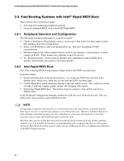
... memory count and the search for a diskette drive. These features may be so fast that the Intel logo screen (or a custom logo splash screen) will not be seen. In the Boot Menu: • Set the hard disk drive as logo displays, screen repaints, or mode changes in the Drive Configuration Submenu of painting complex graphic images and changing video modes. • Enable Intel Rapid BIOS Boot. Some monitors initialize and communicate with the BIOS more quickly. 3.8.2 Intel Rapid BIOS Boot Use...
... memory count and the search for a diskette drive. These features may be so fast that the Intel logo screen (or a custom logo splash screen) will not be seen. In the Boot Menu: • Set the hard disk drive as logo displays, screen repaints, or mode changes in the Drive Configuration Submenu of painting complex graphic images and changing video modes. • Enable Intel Rapid BIOS Boot. Some monitors initialize and communicate with the BIOS more quickly. 3.8.2 Intel Rapid BIOS Boot Use...

Product Specification
Page 100
... error occurred in the keyboard connection. BIOS Error Messages (continued) Error Message Explanation Update OK! The system Jumper should be bad. If no memory was added there may be bad. Memory Size Changed Memory size has changed since the last boot. Keyboard Error Error in onboard memory at an unknown address. This error is followed by NVRAM, CMOS, and passwords have been cleared. On Board Parity Error A parity error occurred in onboard memory. Memory Size Increased Memory size has increased since the last boot. User must enter Setup...
... error occurred in the keyboard connection. BIOS Error Messages (continued) Error Message Explanation Update OK! The system Jumper should be bad. If no memory was added there may be bad. Memory Size Changed Memory size has changed since the last boot. Keyboard Error Error in onboard memory at an unknown address. This error is followed by NVRAM, CMOS, and passwords have been cleared. On Board Parity Error A parity error occurred in onboard memory. Memory Size Increased Memory size has increased since the last boot. User must enter Setup...

Product Specification
Page 101
... POST card must be transferred to main BIOS. Some codes are repeated in PCI bus connector 1. The tables below offer descriptions of POST Operation NMI is initialized. Onboard KBC, RTC enabled (if present). Keyboard controller BAT test, CPU ID saved, and going to boot from floppy. To check recovery mode and verify main BIOS checksum. Uncompress the main BIOS module. Table 52. Initialize extra (Intel Recovery) Module. If reading of POST Operation Onboard Floppy Controller (if any) is Disabled. Boot...
... POST card must be transferred to main BIOS. Some codes are repeated in PCI bus connector 1. The tables below offer descriptions of POST Operation NMI is initialized. Onboard KBC, RTC enabled (if present). Keyboard controller BAT test, CPU ID saved, and going to boot from floppy. To check recovery mode and verify main BIOS checksum. Uncompress the main BIOS module. Table 52. Initialize extra (Intel Recovery) Module. If reading of POST Operation Onboard Floppy Controller (if any) is Disabled. Boot...

Product Specification
Page 103
... cleared. (SOFT RESET) Going to save memory size information. Memory above 1M found and verified. Memory size display started . Going to check for relocation/shadow. Memory testing/initialization above 1M. CPU registers are saved. Going to check memory wrap around test done. A20 address line, parity/NMI disable successful. Hit message cleared. To initialize 8259 interrupt controller. Keyboard reset error/stuck key found and verified. Runtime Code Uncompressed in real mode...
... cleared. (SOFT RESET) Going to save memory size information. Memory above 1M found and verified. Memory size display started . Going to check for relocation/shadow. Memory testing/initialization above 1M. CPU registers are saved. Going to check memory wrap around test done. A20 address line, parity/NMI disable successful. Hit message cleared. To initialize 8259 interrupt controller. Keyboard reset error/stuck key found and verified. Runtime Code Uncompressed in real mode...

Product Specification
Page 106
... a beep code (one long tone followed by two short tones) during POST if the video configuration fails (a faulty video card or no card installed) or if an external ROM module does not properly checksum to the operating system. Intel Desktop Board D915GAV/D915GAG Technical Product Specification Table 56 describes the lower nibble of the high byte and indicates the bus on page 14 4.5 BIOS Beep Codes Whenever a recoverable error occurs during POST, the BIOS displays...
... a beep code (one long tone followed by two short tones) during POST if the video configuration fails (a faulty video card or no card installed) or if an external ROM module does not properly checksum to the operating system. Intel Desktop Board D915GAV/D915GAG Technical Product Specification Table 56 describes the lower nibble of the high byte and indicates the bus on page 14 4.5 BIOS Beep Codes Whenever a recoverable error occurs during POST, the BIOS displays...


