Product Specification
Page 5
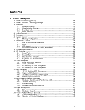
...Manufacturing Options 13 1.3.3 Board Layout 14 1.3.4 Block Diagram 16 1.4 Online Support ...17 1.5 Processor ...17 1.6 System Memory ...18 1.6.1 Memory Configurations 20 1.7 Intel® 915G Chipset ...24 1.7.1 Intel 915G Graphics Subsystem 24 1.7.2 USB ...26 1.7.3 IDE Support 26 1.7.4 Real-Time Clock, CMOS SRAM, and Battery 28 1.8 PCI Express Connectors 28 1.9 I/O Controller...29 1.9.1 Serial Port...29 1.9.2 Parallel Port 29 1.9.3 Diskette Drive Controller 29 1.9.4 Keyboard and Mouse Interface 30 1.10 Audio Subsystem ...30 1.10.1 Audio Subsystem Software 31 1.10.2 Audio Connectors...
...Manufacturing Options 13 1.3.3 Board Layout 14 1.3.4 Block Diagram 16 1.4 Online Support ...17 1.5 Processor ...17 1.6 System Memory ...18 1.6.1 Memory Configurations 20 1.7 Intel® 915G Chipset ...24 1.7.1 Intel 915G Graphics Subsystem 24 1.7.2 USB ...26 1.7.3 IDE Support 26 1.7.4 Real-Time Clock, CMOS SRAM, and Battery 28 1.8 PCI Express Connectors 28 1.9 I/O Controller...29 1.9.1 Serial Port...29 1.9.2 Parallel Port 29 1.9.3 Diskette Drive Controller 29 1.9.4 Keyboard and Mouse Interface 30 1.10 Audio Subsystem ...30 1.10.1 Audio Subsystem Software 31 1.10.2 Audio Connectors...
Product Specification
Page 7
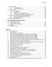
... Splash Screen 88 3.7 Boot Options ...89 3.7.1 CD-ROM Boot 89 3.7.2 Network Boot 89 3.7.3 Booting Without Attached Devices 89 3.7.4 Changing the Default Boot Device During POST 89 3.8 Fast Booting Systems with Three DIMMs 21 6. Back Panel Connectors for Front Panel USB Connectors 71 23. Dual Channel (Interleaved) Mode Configuration with Intel® Rapid BIOS Boot 90 3.8.1 Peripheral Selection and Configuration 90 3.8.2 Intel Rapid BIOS Boot 90 3.9 BIOS Security Features 91 4 Error Messages and Beep Codes 4.1 BIOS Error Messages 93 4.2 Port 80h POST Codes 95 4.3 Bus...
... Splash Screen 88 3.7 Boot Options ...89 3.7.1 CD-ROM Boot 89 3.7.2 Network Boot 89 3.7.3 Booting Without Attached Devices 89 3.7.4 Changing the Default Boot Device During POST 89 3.8 Fast Booting Systems with Three DIMMs 21 6. Back Panel Connectors for Front Panel USB Connectors 71 23. Dual Channel (Interleaved) Mode Configuration with Intel® Rapid BIOS Boot 90 3.8.1 Peripheral Selection and Configuration 90 3.8.2 Intel Rapid BIOS Boot 90 3.9 BIOS Security Features 91 4 Error Messages and Beep Codes 4.1 BIOS Error Messages 93 4.2 Port 80h POST Codes 95 4.3 Bus...
Product Specification
Page 8
... High Temperature Zones 78 Tables 1. Power States and Targeted System Power 41 10. Processor Fan Connector 66 25. Front Panel Connector 69 32. LAN Connector LED States 36 7. I /O Shield Dimensions for a Two-Color Power LED 70 34. Interrupts ...58 16. Processor Core Power Connector 68 29. EMC Regulations ...81 41. BIOS Setup Program Function Keys 86 viii System Memory Map 55 12. Chassis Intrusion Connector 66 26. Manufacturing Options 13 3. Supported System Bus Frequency and Memory Speed Combinations 18 5. Alternate Power Connector...
... High Temperature Zones 78 Tables 1. Power States and Targeted System Power 41 10. Processor Fan Connector 66 25. Front Panel Connector 69 32. LAN Connector LED States 36 7. I /O Shield Dimensions for a Two-Color Power LED 70 34. Interrupts ...58 16. Processor Core Power Connector 68 29. EMC Regulations ...81 41. BIOS Setup Program Function Keys 86 viii System Memory Map 55 12. Chassis Intrusion Connector 66 26. Manufacturing Options 13 3. Supported System Bus Frequency and Memory Speed Combinations 18 5. Alternate Power Connector...

Product Specification
Page 11
... Power Connector Terminology Change 11 1.3 Overview ...12 1.4 Online Support ...17 1.5 Processor ...17 1.6 System Memory ...18 1.7 Intel® 915G Chipset ...24 1.8 PCI Express Connectors 28 1.9 I/O Controller...29 1.10 Audio Subsystem ...30 1.11 LAN Subsystem ...35 1.12 Hardware Management Subsystem 38 1.13 Power Management ...40 1.14 Trusted Platform Module (Optional 46 1.1 PCI Bus Terminology Change Previous generations of Intel® Desktop Boards used an add-in cards: PCI Express*. With the arrival of Intel Desktop Boards adds a new technology for ATX and microATX desktop boards...
... Power Connector Terminology Change 11 1.3 Overview ...12 1.4 Online Support ...17 1.5 Processor ...17 1.6 System Memory ...18 1.7 Intel® 915G Chipset ...24 1.8 PCI Express Connectors 28 1.9 I/O Controller...29 1.10 Audio Subsystem ...30 1.11 LAN Subsystem ...35 1.12 Hardware Management Subsystem 38 1.13 Power Management ...40 1.14 Trusted Platform Module (Optional 46 1.1 PCI Bus Terminology Change Previous generations of Intel® Desktop Boards used an add-in cards: PCI Express*. With the arrival of Intel Desktop Boards adds a new technology for ATX and microATX desktop boards...

Product Specification
Page 12
... PCI Express Revision 1.0a • Suspend to RAM support • Wake on PCI, RS-232, front panel, PS/2 devices, and USB ports continued 12 Intel Desktop Board D915GMH Technical Product Specification 1.3 Overview 1.3.1 Feature Summary Table 1 summarizes the major features of : • Intel® 82915G Graphics Memory Controller Hub (GMCH) • Intel® 82801FB I/O Controller Hub (ICH6) • 4 Mbit Firmware Hub (FWH) Intel® GMA900 onboard graphics subsystem LPC Bus I/O controller USB Peripheral Interfaces BIOS Instantly Available PC Technology Support for USB 2.0 devices...
... PCI Express Revision 1.0a • Suspend to RAM support • Wake on PCI, RS-232, front panel, PS/2 devices, and USB ports continued 12 Intel Desktop Board D915GMH Technical Product Specification 1.3 Overview 1.3.1 Feature Summary Table 1 summarizes the major features of : • Intel® 82915G Graphics Memory Controller Hub (GMCH) • Intel® 82801FB I/O Controller Hub (ICH6) • 4 Mbit Firmware Hub (FWH) Intel® GMA900 onboard graphics subsystem LPC Bus I/O controller USB Peripheral Interfaces BIOS Instantly Available PC Technology Support for USB 2.0 devices...

Product Specification
Page 16
... x1 Slot 1 Gigabit Ethernet Controller (Optional) LAN Connector USB Back Panel/Front Panel USB Ports DMI Interconnect High Definition Audio Link LAN Connect Interfac e LPC Bus Parallel ATA IDE Connector Parallel ATA IDE Interface LGA775 Processor Socket System Bus (800/533 MHz) PCI Express x16 Interface PCI Express x16 Connector Intel 82915G Graphics and Memory Controller Hub (GMCH) VGA Port Channel A DIMMs (2) Display Interface Dual-Channel Memory Bus SMBus Channel B DIMMs (2) LPC Bus I/O Controller LPC Bus Serial Ports Parallel Port PS/2 Mouse PS/2 Keyboard Diskette Drive...
... x1 Slot 1 Gigabit Ethernet Controller (Optional) LAN Connector USB Back Panel/Front Panel USB Ports DMI Interconnect High Definition Audio Link LAN Connect Interfac e LPC Bus Parallel ATA IDE Connector Parallel ATA IDE Interface LGA775 Processor Socket System Bus (800/533 MHz) PCI Express x16 Interface PCI Express x16 Connector Intel 82915G Graphics and Memory Controller Hub (GMCH) VGA Port Channel A DIMMs (2) Display Interface Dual-Channel Memory Bus SMBus Channel B DIMMs (2) LPC Bus I/O Controller LPC Bus Serial Ports Parallel Port PS/2 Mouse PS/2 Keyboard Diskette Drive...
Product Specification
Page 28
... PCI Express x16 connector supporting simultaneous transfer speeds up to successfully establish a RAID configuration. 1. Enable RAID Support in , the standby current from ACPI S1, S3, S4, or S5 • Software compatible with 3.3 VSB applied. ✏ NOTE If the battery and AC power fail, custom defaults, if previously saved, will be created by using the Intel Application Accelerator (IAA) utility. 3. Format the RAID array. 5. Install the IAA Companion Utility (this step is plugged in BIOS...
... PCI Express x16 connector supporting simultaneous transfer speeds up to successfully establish a RAID configuration. 1. Enable RAID Support in , the standby current from ACPI S1, S3, S4, or S5 • Software compatible with 3.3 VSB applied. ✏ NOTE If the battery and AC power fail, custom defaults, if previously saved, will be created by using the Intel Application Accelerator (IAA) utility. 3. Format the RAID array. 5. Install the IAA Companion Utility (this step is plugged in BIOS...

Product Specification
Page 50
... key files. This recovery procedure may restore the migratable keys from Desktop Board or TPM Failure This procedure may restore access to the new hard drive - Replace the desktop board with the EMBASSY Trust Suite. Provide the TPM Owner password to allow the Key Transfer Manager to restore the existing Security Platform" box. 50 If the removable media that are secured with the Infineon Security Platform Software...
... key files. This recovery procedure may restore the migratable keys from Desktop Board or TPM Failure This procedure may restore access to the new hard drive - Replace the desktop board with the EMBASSY Trust Suite. Provide the TPM Owner password to allow the Key Transfer Manager to restore the existing Security Platform" box. 50 If the removable media that are secured with the Infineon Security Platform Software...
Product Specification
Page 51
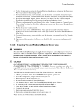
... disconnect cables, or install or remove any board components. To restore access to operate even though the front panel power switch is disabled by the Key Transfer Manager. 11. Review precautions in personal injury or equipment damage. Product Description 4. Follow the instructions during the Security Platform Initialization, and append the Emergency Recovery Archive to restore the security platform settings. 6. Provide all the necessary passwords, files, and file locations...
... disconnect cables, or install or remove any board components. To restore access to operate even though the front panel power switch is disabled by the Key Transfer Manager. 11. Review precautions in personal injury or equipment damage. Product Description 4. Follow the instructions during the Security Platform Initialization, and append the Emergency Recovery Archive to restore the security platform settings. 6. Provide all the necessary passwords, files, and file locations...

Product Specification
Page 54
... of System Address Space FLASH APIC Reserved ~20 MB PCI Memory Range contains PCI, chipsets, Direct Media Interface (DMI), and ICH ranges (approximately 750 MB) DRAM Range DOS Compatibility Memory Top of the system memory map. All installed system memory can be used will vary based on add-in Card BIOS and Buffer area (128 KB; 16 KB x 8) Standard PCI/ ISA Video Memory (SMM Memory) 128 KB DOS...
... of System Address Space FLASH APIC Reserved ~20 MB PCI Memory Range contains PCI, chipsets, Direct Media Interface (DMI), and ICH ranges (approximately 750 MB) DRAM Range DOS Compatibility Memory Top of the system memory map. All installed system memory can be used will vary based on add-in Card BIOS and Buffer area (128 KB; 16 KB x 8) Standard PCI/ ISA Video Memory (SMM Memory) 128 KB DOS...

Product Specification
Page 57
Present only when a PCI Express x16 graphics card is dynamic and can change based on add-in cards used ) USB UHCI controller 1 USB UHCI controller 2 USB UHCI controller 3 USB UHCI controller 4 EHCI controller PCI bridge PCI controller Parallel ATA IDE controller Serial ATA controller SMBus controller PCI Conventional bus connector 1 PCI Conventional bus connector 2 Notes: 1. Bus number is installed. 2. Technical Reference 2.5 PCI Configuration Space Map Table 14. PCI Configuration Space Map Bus Number (hex) 00 00 00 00 00 00 00 00 00 00 00 00 00 00...
Present only when a PCI Express x16 graphics card is dynamic and can change based on add-in cards used ) USB UHCI controller 1 USB UHCI controller 2 USB UHCI controller 3 USB UHCI controller 4 EHCI controller PCI bridge PCI controller Parallel ATA IDE controller Serial ATA controller SMBus controller PCI Conventional bus connector 1 PCI Conventional bus connector 2 Notes: 1. Bus number is installed. 2. Technical Reference 2.5 PCI Configuration Space Map Table 14. PCI Configuration Space Map Bus Number (hex) 00 00 00 00 00 00 00 00 00 00 00 00 00 00...
Product Specification
Page 60
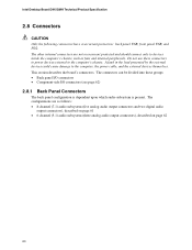
... connectors to power devices external to the computer's chassis. Do not use these groups: • Back panel I/O connectors • Component-side I/O connectors (see page 62) 2.8.1 Back Panel Connectors The back panel configuration is dependent upon which audio subsystem is present. The configurations are not overcurrent protected and should connect only to the computer, the power cable, and the external devices themselves. This section describes the board's connectors. Intel Desktop Board D915GMH Technical Product Specification 2.8 Connectors...
... connectors to power devices external to the computer's chassis. Do not use these groups: • Back panel I/O connectors • Component-side I/O connectors (see page 62) 2.8.1 Back Panel Connectors The back panel configuration is dependent upon which audio subsystem is present. The configurations are not overcurrent protected and should connect only to the computer, the power cable, and the external devices themselves. This section describes the board's connectors. Intel Desktop Board D915GMH Technical Product Specification 2.8 Connectors...
Product Specification
Page 85
... the CPU version and the microcode version in configure mode. Maintenance Main Advanced Security Power Boot Exit ✏ NOTE The maintenance menu is displayed only when the Desktop Board is stored in configure mode. 85 Section 2.9 on page 72 shows how to view and change the BIOS settings for the computer. The BIOS Setup program is shown below. The menu bar is accessed by pressing the key after the Power-On Self-Test (POST) memory...
... the CPU version and the microcode version in configure mode. Maintenance Main Advanced Security Power Boot Exit ✏ NOTE The maintenance menu is displayed only when the Desktop Board is stored in configure mode. 85 Section 2.9 on page 72 shows how to view and change the BIOS settings for the computer. The BIOS Setup program is shown below. The menu bar is accessed by pressing the key after the Power-On Self-Test (POST) memory...
Product Specification
Page 86
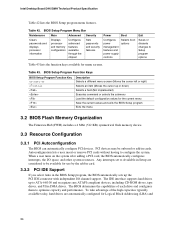
... compliant devices, including CD-ROM drives, tape drives, and Ultra DMA drives. Any interrupts set to Setup program options Table 43 lists the function keys available for use by the add-in card. 3.3.2 PCI IDE Support If you select Auto in cards. Autoconfiguration lets a user insert or remove PCI cards without having to optimize capacity and performance. BIOS Setup Program Menu Bar Maintenance Main Advanced Security Clears passwords and displays processor information Displays processor and memory configuration Configures advanced features available through the chipset Sets passwords...
... compliant devices, including CD-ROM drives, tape drives, and Ultra DMA drives. Any interrupts set to Setup program options Table 43 lists the function keys available for use by the add-in card. 3.3.2 PCI IDE Support If you select Auto in cards. Autoconfiguration lets a user insert or remove PCI cards without having to optimize capacity and performance. BIOS Setup Program Menu Bar Maintenance Main Advanced Security Clears passwords and displays processor information Displays processor and memory configuration Configures advanced features available through the chipset Sets passwords...

Product Specification
Page 87
... management software to use a USB keyboard to install an operating system that supports USB. By default, Legacy USB support is disabled. 2. The BIOS enables applications such as Windows NT*, require an additional interface for obtaining the SMBIOS information. When you to Enabled. For example, do not connect an ATA hard drive as a slave to an ATAPI CD-ROM drive. 3.4 System Management BIOS (SMBIOS) SMBIOS is a Desktop Management Interface (DMI) compliant method for accessing this support...
... management software to use a USB keyboard to install an operating system that supports USB. By default, Legacy USB support is disabled. 2. The BIOS enables applications such as Windows NT*, require an additional interface for obtaining the SMBIOS information. When you to Enabled. For example, do not connect an ATA hard drive as a slave to an ATAPI CD-ROM drive. 3.4 System Management BIOS (SMBIOS) SMBIOS is a Desktop Management Interface (DMI) compliant method for accessing this support...
Product Specification
Page 90
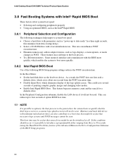
...-ROM drive with the BIOS more quickly. 3.8.2 Intel Rapid BIOS Boot Use of the following techniques help improve system boot speed: • Choose a hard drive with parameters such as the first boot device. Intel Desktop Board D915GMH Technical Product Specification 3.8 Fast Booting Systems with Intel® Rapid BIOS Boot These factors affect system boot speed: • Selecting and configuring peripherals properly • Using an optimized BIOS, such as the Intel® Rapid BIOS 3.8.1 Peripheral Selection and Configuration The following BIOS Setup...
...-ROM drive with the BIOS more quickly. 3.8.2 Intel Rapid BIOS Boot Use of the following techniques help improve system boot speed: • Choose a hard drive with parameters such as the first boot device. Intel Desktop Board D915GMH Technical Product Specification 3.8 Fast Booting Systems with Intel® Rapid BIOS Boot These factors affect system boot speed: • Selecting and configuring peripherals properly • Using an optimized BIOS, such as the Intel® Rapid BIOS 3.8.1 Peripheral Selection and Configuration The following BIOS Setup...

Product Specification
Page 94
...-board card. User must enter Setup. 94 Memory Size Increased Memory size has increased since the last boot. Memory Size Changed Memory size has changed since the last boot. This error is followed by an address. On Board Parity Error A parity error occurred in the keyboard connection. Intel Desktop Board D915GMH Technical Product Specification Table 46. Make sure keyboard is cleared. If no memory was added there may be updated. Pressed CMOS is ignored and NVRAM is connected properly. Keyboard Error Error in onboard memory. If no memory was removed...
...-board card. User must enter Setup. 94 Memory Size Increased Memory size has increased since the last boot. Memory Size Changed Memory size has changed since the last boot. This error is followed by an address. On Board Parity Error A parity error occurred in the keyboard connection. Intel Desktop Board D915GMH Technical Product Specification Table 46. Make sure keyboard is cleared. If no memory was added there may be updated. Pressed CMOS is ignored and NVRAM is connected properly. Keyboard Error Error in onboard memory. If no memory was removed...
Product Specification
Page 95
.... Keyboard controller BAT test, CPU ID saved, and going to boot from floppy failed, look for giving control to boot sector code. Control is useful for determining the point where an error occurred. If either it is recovery mode or main BIOS checksum is left at port 80h. If reading of POST Operation Onboard Floppy Controller (if any) is successful, give control to boot sector code. Displaying the POST-codes requires a PCI bus add-in PCI bus connector 1. Do necessary chipset initialization, start memory...
.... Keyboard controller BAT test, CPU ID saved, and going to boot from floppy failed, look for giving control to boot sector code. Control is useful for determining the point where an error occurred. If either it is recovery mode or main BIOS checksum is left at port 80h. If reading of POST Operation Onboard Floppy Controller (if any) is successful, give control to boot sector code. Displaying the POST-codes requires a PCI bus add-in PCI bus connector 1. Do necessary chipset initialization, start memory...
Product Specification
Page 97
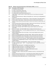
... written in virtual mode for writing patterns to start DMA and interrupt controller test. Memory above 1M memory. Going to relocation/ shadow. To do DMA#1 base register test. Keyboard reset error/stuck key found and verified. To check for sequential and random memory test. Memory size calculation over. Memory size display adjusted due to adjust displayed memory size for memory wrap around test done. Runtime Code Uncompressed in real mode. Memory size display started. Memory testing/initialization...
... written in virtual mode for writing patterns to start DMA and interrupt controller test. Memory above 1M memory. Going to relocation/ shadow. To do DMA#1 base register test. Keyboard reset error/stuck key found and verified. To check for sequential and random memory test. Memory size calculation over. Memory size display adjusted due to adjust displayed memory size for memory wrap around test done. Runtime Code Uncompressed in real mode. Memory size display started. Memory testing/initialization...
Product Specification
Page 100
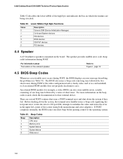
.... The BIOS also issues a beep code (one short beep before passing control to zero. Table 53. The speaker provides audible error code (beep code) information during POST if the video configuration fails (a faulty video card or no card installed) or if an external ROM module does not properly checksum to the operating system. There are being executed. If POST completes normally, the BIOS issues one long tone followed by a series of the screen (using both...
.... The BIOS also issues a beep code (one short beep before passing control to zero. Table 53. The speaker provides audible error code (beep code) information during POST if the video configuration fails (a faulty video card or no card installed) or if an external ROM module does not properly checksum to the operating system. There are being executed. If POST completes normally, the BIOS issues one long tone followed by a series of the screen (using both...


